Drop-In Double Fiskars Knife Dock w blade storage
Made by EvilStark
Created 3 months ago
Remixed 2 times
Description
A custom Gridfinity-compatible tool tray designed to dock the Fiskars Pro Retractable Utility Knife (model 770210-1001). The heavy-duty aesthetic of the Fiskars knife calls for a simple, rugged docking station. Built on a standard 4x2 unit footprint, this tray swallows the knife whole while leaving generous finger grabs to pop it out fast when you're mid-project.
Design Features
- 4x2 Gridfinity Footprint: Drops seamlessly into standard 42mm grid baseplates.
- Tapered Base Profiles: Easy alignment and standard Gridfinity locking dimensions.
- Ample Finger Clearance: Scalloped sides mean no digging around to retrieve your blade.
- Slider Channel: An extra-deep central groove ensures the blade slider button doesn't bottom out.
Images
More like this
Explore more in Storage & Organization →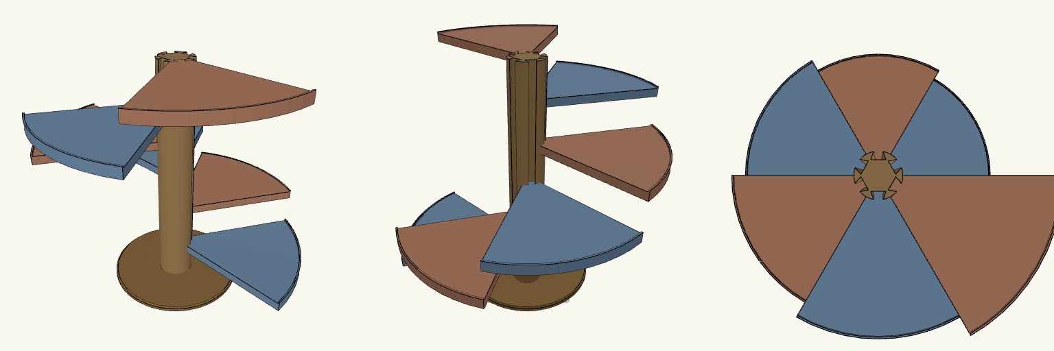
Clip-In Spiral Shoe Rack, 6 Steps
Spiral shoe rack with six 60° steps around a central column on a round base, one pair of shoes per step. Each step has a dovetail tongue that slides down into a matching slot in the column, so steps can be removed or attached individually. Steps: 18 mm flat plates, 4 mm outer lip, 90 mm rise per step Overall size: 600 mm diameter, 540 mm tall Base: 300 mm diameter, 12 mm thick, chamfered Clip: dovetail 15 mm deep, 0.3 mm slot clearance Removal: lift the step straight up Print steps flat; column upright; large size may need scaling or sectioning
Four-Compartment Cutlery Separator Tray
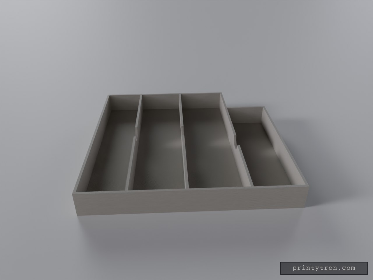
What it's for A four-compartment cutlery separator tray for a drawer, with semi-round finger cutouts in each divider so utensils lift out easily. Dimensions Overall height: 30 mm, with a 3 mm base and 3 mm walls Three compartments 240 mm long: 50, 60 and 65 mm wide One 55 mm wide, 185 mm long compartment beside the 65 mm one Finger cutouts: 24 mm diameter semicircles centred on each divider Remix ideas Change the cutout radius for deeper or shallower scoops Split the tray into pieces for smaller print beds Add a lip or feet for drawer grip
Two-Piece Sliding Storage Drawer with Spring Release
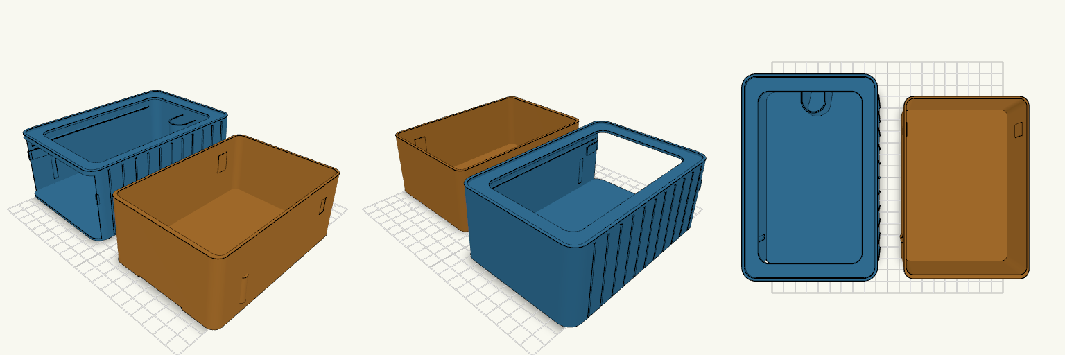
A minimalist two-piece sliding storage drawer: a ribbed outer housing with an open front and a separate inner drawer with a flush, handle-free face. The housing measures 100 × 150 × 60 mm with 10 mm rounded outer corners and 1.6 mm walls. Vertical ribbing stiffens the side walls, and thin 45° guide rails keep the drawer aligned. The guide rails and side stop tabs stay inside the outer walls, with only the ribs standing proud by design; the front ends of the rails stop inside the rounded front corners. The top is an open frame with a 12 mm solid rim, thickened to 3.4 mm so the stacking recess does not cut through. The drawer slides on the rails and locks closed with rounded snap bumps that seat into grooves in the housing. Push the drawer inward to release the bumps; the rear U-shaped leaf spring then pushes it forward. The spring is 0.95 mm thick and 40 mm wide, anchored to the inner back wall and touching the floor only where it meets that wall. A 45° chamfer under its bottom edge lifts the loop clear of the floor as it runs forward, so it flexes freely and still prints without supports — the trade-off is a shorter front loop, so the spring is on the soft side. A 45° finger bevel under the bottom front edge gives a hidden pull once the drawer has popped out. Flexible side stop tabs catch pockets near the back of the drawer, limiting travel to about 95 mm; press the tabs aside to remove the drawer fully. The stop pockets are 1.2 mm deep with 1.4 mm of solid wall behind them. The housing also stacks: a 1.5 mm bottom foot, inset 2.2 mm with a 45° chamfer, sits in a matching 1.8 mm recessed step on the top rim with 0.3 mm clearance. Housing: 100 × 150 × 60 mm, ribbed sides, open top with 12 mm rim, 10 mm rounded corners, 1.6 mm walls Drawer: 95.7 × 135 × 53.2 mm, flush front, no handle, side snap bumps Release: push-push detent with rear U-spring Pull: hidden 45° finger bevel under the front bottom edge Stop: flexible side tabs limit travel to about 95 mm; press aside for full removal Stacking: 1.5 mm bottom foot and matching 1.8 mm top recess Printing: two separate pieces, no supports, overhangs 45° or shallower Tuning: spring force and detent interference may need adjustment after a test print
Gridfinity 4×4 Feilen-Bins mit 5 Fächern
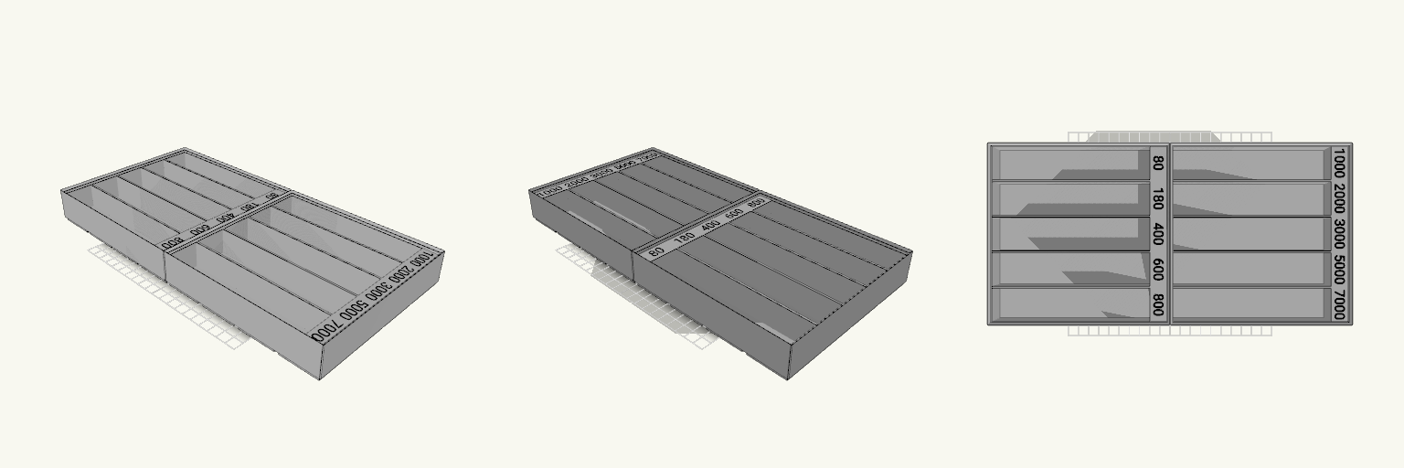
Die Feilen-Bins sind Gridfinity-Einsätze für die 42-mm-Rasterplatte im Raster 4×4. Es sind zwei getrennte Bins mit je 167,5 × 167,5 mm Grundfläche und 35,4 mm Gesamthöhe; Unterboden und Stapelrand sind darin enthalten. Jeder Bin hat fünf offene Fächer. Die beiden Bins sind eigene Teile und lassen sich einzeln drucken; ein Druckbett ab etwa 180 mm reicht pro Bin. Die Beschriftung ist als drittes Teil angelegt. Aufbau 5 Fächer je Bin, je etwa 31,3 mm breit Fächer am +X-Ende um 16 mm gekürzt; dort steht ein massiver Block für die Zahl, die nutzbare Fachlänge beträgt rund 146,7 mm 1,6 mm Steg zwischen den Fächern, 2,4 mm Außenwand Nutzbare Fachtiefe rund 29 mm unter dem Stapelrand Stapelrand oben bleibt frei Zwei getrennte Bins, kein zusammenhängendes Teil Beschriftung Zehn Zahlen auf beide Bins verteilt: 80, 180, 400, 600 und 800 im linken Bin; 1000, 2000, 3000, 5000 und 7000 im rechten Reihenfolge steigt in jedem Bin von hinten (+Y) nach vorn (−Y): 80 ganz hinten, 1000 bzw. 7000 vorn Zahlen 9 mm hoch, 0,6 mm eingelassen und bündig mit der Oberfläche, um 180° gedreht und quer in Y-Richtung gelesen Bins weiß, Schrift schwarz; die Beschriftung als eigenes Teil per Farbwechsel oder Pause drucken Vor dem Druck prüfen Druckbett: mindestens etwa 180 mm pro Bin; die beiden Bins getrennt drucken Fachlänge: rund 146,7 mm durch den Beschriftungsblock am +X-Ende Fachbreite: rund 31,3 mm; was breiter ist, liegt auf den 1,6 mm breiten Stegen auf Fachtiefe: rund 29 mm unter dem Stapelrand Nicht geeignet für Teile länger als rund 146,7 mm, breiter als rund 31 mm oder höher als rund 29 mm, hochkant gestellte Feilen und alles, was über den Stapelrand hinausragt. Die Fächer sind offene, durchgehende Rillen ohne Einzelunterteilung; die Zahlen sind fest eingebaut, nicht austauschbar.
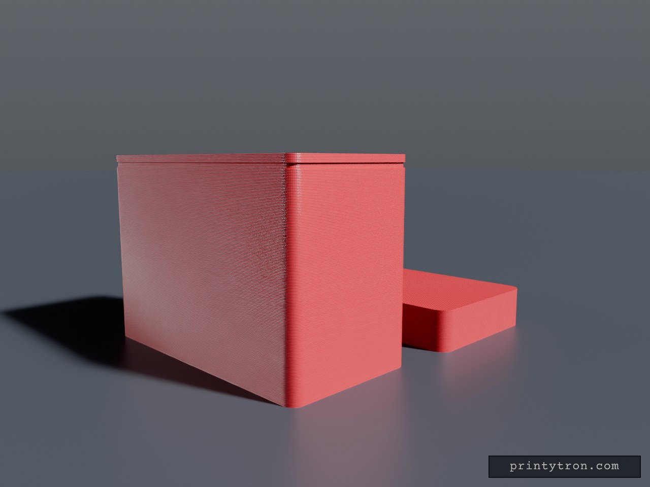
Two-Vial Storage Case with Snap Lid
A storage case for two 31 mm round, 71 mm tall vials, with a separate snap-on lid. Body and lid are two separate pieces, laid out side by side so each can be exported as its own STL. Each vial sits in its own round pocket, with a 4 mm solid wall between the pockets so the vials never touch at the base. The pockets have 0.6 mm of clearance and a 3 mm floor. A finger slot on the front of each pocket makes lifting a vial out easier. The lid fits over the top of the body and clicks onto a shallow groove around the rim. It leaves room for the vial tops that stick out above the body. Vial size: 31 mm diameter, 71 mm tall Body height: 60 mm, 2.5 mm walls Lid: 5 mm overlap onto the body, with an inward snap bead Made with resin printers such as the Elegoo Mars in mind
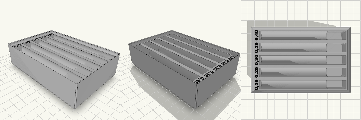
Gridfinity-Einsatz 3×2 für 5 Röhrchen Ø13 mm
Ein Gridfinity-Einsatz im 3×2-Raster mit 36 mm Gesamthöhe inklusive Fuß, der fünf längs liegende Mulden für Röhrchen von 13 mm Durchmesser und 110 mm Länge aufnimmt. Die Röhrchen werden von oben eingelegt; die Mulden sind oben offen. Vor den Mulden steht eine Beschriftung mit den Werten 0,20 / 0,25 / 0,30 / 0,35 / 0,40, von vorn nach hinten. Unter dem rechten Ende jeder Mulde sitzt eine zusätzliche Druckmulde in derselben Breite wie die Röhrchen-Mulde, die bis ans Muldenende geführt ist: Wird dort auf das eingelegte Röhrchen gedrückt, kippt es um die Kante und das gegenüberliegende Ende hebt sich zum Greifen an. Einsatz und Beschriftung sind getrennte Teile; die Beschriftung ist 0,8 mm tief in einer passenden Aussparung eingelassen, schließt oben bündig mit der Fläche des Einsatzes ab und liegt vollständig frei, sodass der Stapelrand sie nicht verdeckt. Die Mulden sind gegenüber der Beschriftung um 2,5 mm nach rechts versetzt, damit die Schrift nicht in die Mulden läuft. Der Einsatz ist weiß, die Schrift schwarz. Technische Daten Belegung: 3×2 Gridfinity-Felder, Rastermaß 42 mm Außenmaß: 125,5 × 83,5 × 36 mm (Fuß eingerechnet) Körperhöhe: 31,6 mm, darüber Stapelrand bis 36 mm Mulden: 5 Stück, je 13,6 mm breit und 112 mm lang, Abstand 16 mm, Muldenmitte auf 28 mm Höhe Druckmulden: je 24 mm lang, 13,6 mm breit und 14 mm tief, am +X-Ende jeder Mulde bis zum Muldenende geführt, nur an einer Seite, um die Auflage des Röhrchens nicht zu halbieren Wand zwischen benachbarten Mulden: 2,4 mm Spiel: rund 0,3 mm je Röhrchen bei Ø13 × 110 mm Schriftabstände: etwa 0,75 mm zum Überhang des Stapelrands und etwa 0,7 mm zur Mulde; rechter Steg etwa 4,25 mm Beschriftung: Werte 0,20 / 0,25 / 0,30 / 0,35 / 0,40; Schrift 4,2 mm hoch, 0,8 mm tief eingelassen, in kräftiger Schrift, um 90° gedreht, von unten nach oben lesbar, am linken Ende jeder Mulde auf einer ebenen Fläche; Einsatz weiß, Schrift schwarz Aufbau: zwei getrennte Teile – Einsatz und Beschriftung; die Schrift sitzt in einer 0,8 mm tiefen Aussparung und überlappt den Einsatz nicht Druck: 0,4-mm-Düse ausreichend; 0,16 mm Schichthöhe glättet die Schriftflanken, 0,2 mm funktioniert ebenfalls Geeignet für Schubladen mit Gridfinity-Auslegung, in denen Röhrchen, Stifte oder ähnliche zylindrische Teile griffbereit und lagestabil untergebracht werden sollen. Der Stapelrand ist für das Setzen eines zweiten Einsatzes ausgelegt; gestapelt kommt pro Einsatz etwa 31,6 mm Höhe dazu, weil der Fuß in den Rand eintaucht. Die Stapelgeometrie ist rechnerisch geprüft, nicht physisch gestapelt oder gedruckt; vor dem Druck mehrerer Einsätze empfiehlt sich ein Probestück. Die Oberkante des Stapelrands läuft spitz aus; bei Passproblemen sind 0,1 bis 0,2 mm mehr Spiel am Rand die übliche Korrektur.