160mm Electronics Enclosure Unit
Created today
Description
A two-piece industrial enclosure built for the SafeSuit Pro Worker Unit. Designed to house an ESP32, LoRa transceiver, and battery, with integrated cable management and hardware mounting points.
The assembly uses a blind-screw design, pulling the cover tight against the base from the rear to leave the front face seamless. The cover includes an internal alignment lip for a rigid friction fit.
Hardware Interfaces
- Internal Mounts: 4x posts for ESP32, 4x posts for LoRa module.
- Fasteners: Uses 4x M3 screws (inserted from the rear base).
- Control Cutouts: Recessed SOS button port (14mm bore), status LED port (4mm), lateral power switch slot, and right-side charging port.
- Cable Routing: Base features internal guide walls; cover features twin 7mm bottom-edge outlets for external sensor cabling.
Images
More like this
Explore more in Workshop & Tools →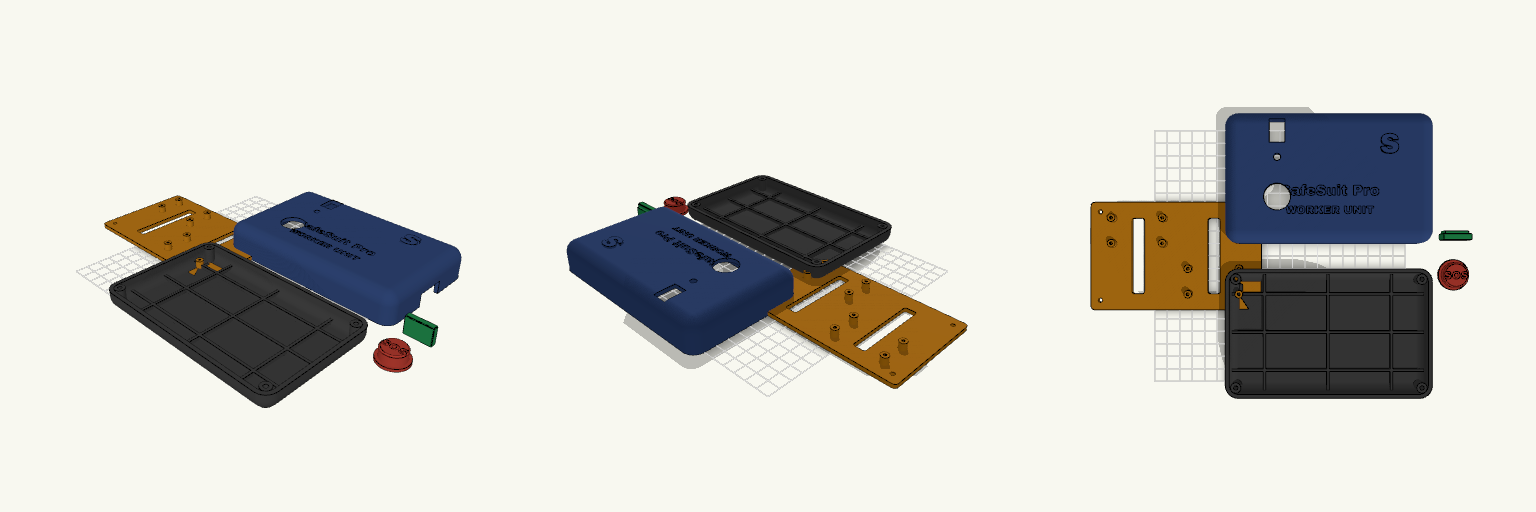
ESP32 / LoRa SafeSuit Enclosure
SafeSuit Pro Worker Unit shell. Mates with a standard ESP32 dev board and a LoRa SX1278 module. A five-piece FDM enclosure with an internal mounting sled, a flanged SOS actuator, and a captive port plug. Fitment Notes Internal mounting plate carries a 40x20mm hole pattern for the ESP32. Uses four M3 screws through the rear cover into the front shell's hidden bosses. Main cavity is roughly 154 x 94 mm internally. Not compatible with extended ESP32-WROVER footprints.
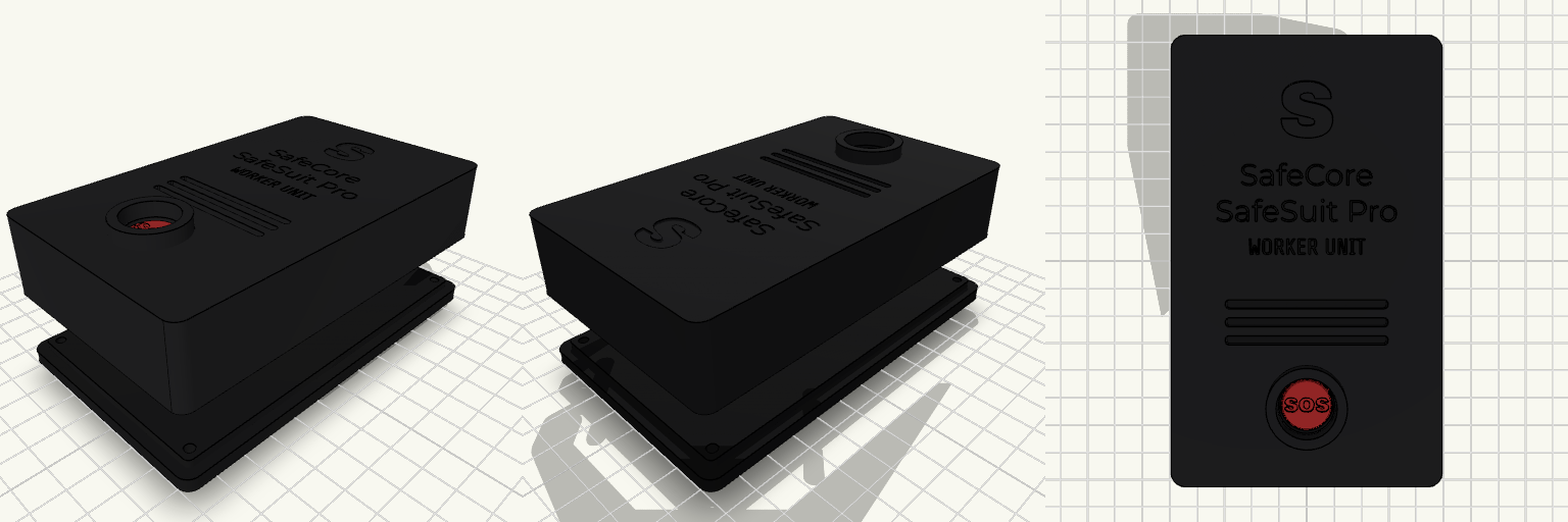
SafeSuit Pro Worker Unit Enclosure
What it's for A rugged, compact enclosure designed specifically for the SafeSuit Pro Worker Unit. It features a heavy-duty front panel with recessed text, horizontal ventilation slots for internal environmental sensors (like the BME680 and gas sensors), and a heavily shrouded SOS button to prevent accidental triggers while keeping it accessible in an emergency. The housing is secured entirely from the rear, ensuring a tamper-resistant front face. Dimensions Overall Size: 75 mm × 125 mm × 35 mm (including rear strap loops). Internal Capacity: 69 mm × 119 mm × 22 mm, providing ample room for an ESP32, LoRa modules, sensors, and a lithium battery. Mounting Interface: Rear panel features 38 mm wide integrated strap loops for chest or harness mounting. Fasteners: Requires four M3 countersunk screws for the rear panel, and standard M2/M2.5 self-tapping screws for internal standoffs. Assembly Print the front shell face-up (or face-down with supports for the button shroud), and the back plate with the strap loops flat against the bed. The SOS button is modelled as a separate piece to allow printing in an emergency red or high-visibility filament before dropping it into the front panel assembly.
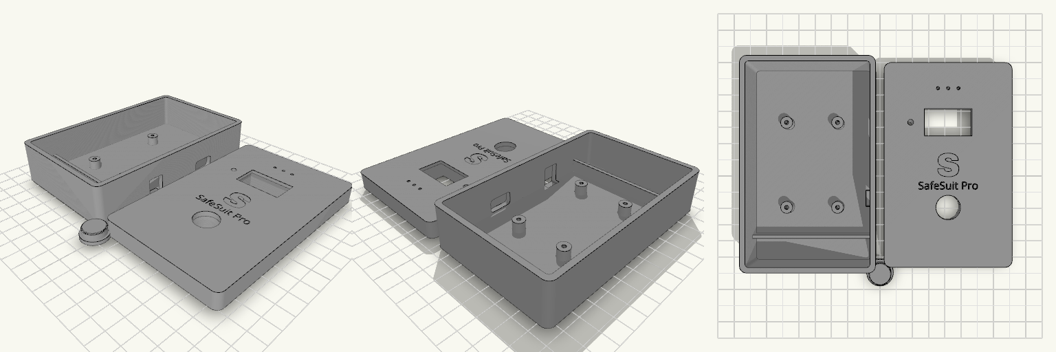
Supervisor Electronics Shell
Generic hobby boxes crack at the screw posts the second time you open them, and their exposed hardware snags on everything in a bag. This is a clean, rugged shell that closes tight without external fasteners and keeps the wiring where it belongs. The front panel traps the alert button from the inside, so it can't be ripped out or jammed sideways. Internal Specs Dimensions: 120 × 75 × 35 mm external. Walls: 3 mm solid shell. Standoffs: Four integrated posts (2.5 mm bore) spaced for a standard ESP32 footprint. Clearance: 0.25 mm tolerance on the friction-fit lid lip. Print flat, no supports required.
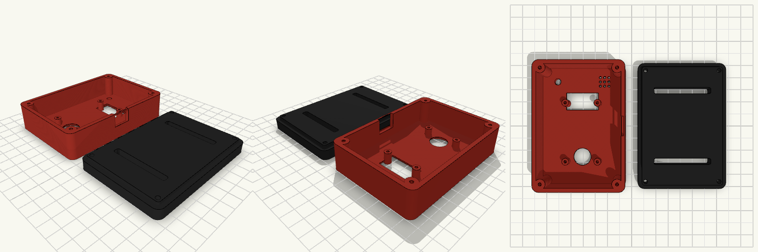
ESP32 SafeCore Controller Enclosure
A dedicated heavy-duty housing for the SafeCore monitor, built entirely around the 30-pin ESP32 dev board footprint and a standard 0.96-inch OLED screen. The two-piece shell is engineered for exact fitment, using a registration lip to keep the halves aligned and transferring shear stress away from the fasteners. Mating Specifications Controller: standard 30-pin ESP32 dev board (25.5 × 47 mm mounting footprint). M2.5 thread-forming posts. Display: 0.96-inch OLED (I2C), sits behind a 26 × 14 mm sloped FDM-safe bezel. Hardware: Four M3 countersunk screws for the rear panel. Indicators: Top-left 5 mm warning LED port and top-right buzzer grille. Mounting: Twin 45 × 5 mm rear slots for standard nylon or Velcro belt straps.
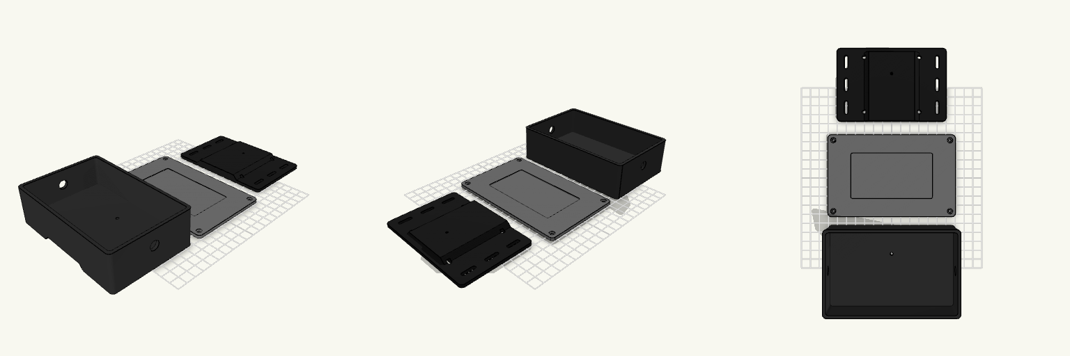
Industrial Wearable Electronics Enclosure
A heavy-duty three-part electronics enclosure designed for wearable prototype suits. Features a slide-and-lock fabric mounting plate that allows the main box to be removed without unthreading straps. Main Box: 140 × 90 × 40 mm with 3 mm walls and 10 mm side ports for external sensors. Mounting Plate: Slotted for fabric straps, featuring a male dovetail rail that slides into the main box and locks with a single pilot screw. Lid: Secures with four M3 screws into tapped corner bosses, featuring a 90 × 50 mm blank recess for a separate logo plate.
Console — Custom Electronics Enclosure
This is a comprehensive, dimensionally accurate parametric enclosure designed for DIY electronics. Laid out to securely house a 16×2 character LCD and four tactile push buttons, it uses standard M3 machine screws with captive nut traps for secure and repeatable assembly. The design separates the tactile switch bodies from the actual visible button caps, ensuring a clean and professional appearance. Features Locating Lip: Recessed rabbet ensures the top cover nests tightly and squarely onto the bottom shell. Component-Specific Pockets: 12×12 mm push-button switches are secured from the underside, operated by independent retained caps. Hidden Mounting: The 16×2 LCD is held flush against the top window from the inside via a custom bezel, keeping the surrounding PCB hidden. Directed Ventilation: Cooling slots are restricted to the lower front face, allowing flush wall mounting at the rear. Hardware Needed 4 × M3 × 12 mm machine screws 4 × M3 hex nuts (5.5 mm across flats) 4 × 12×12×7.3 mm tactile switches 1 × 16×2 Character LCD (JHD162A style)