3D-printable workshop tools & shop upgrades
Drill guides, tool racks, sanding blocks, dust-collection adapters — functional shop gear with real dimensions, ready to print. Browse what makers built, or describe the exact tool you need and Printy makes it.
Need one that fits your exact measurements? Start building →
Newest
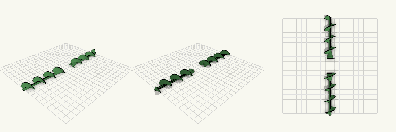
28BYJ-48 5 mm D-Shaft Auger, Flat-Face Flight
Auger for a 28BYJ-48 geared stepper (5 mm shaft with 3 mm flats), printed as two lengthwise halves for gluing. It runs in a 26 mm bore. Key dimensions Flight tip: 23 mm across (1.5 mm per side in a 26 mm bore) Shaft: 5 mm straight Pitch: 24 mm, straight spiral with no taper Flight: 3 mm thick squared blade, lightly rounded edges Motor bore: 5.2 mm D-bore with 3.2 mm flats Check before printing The 11.5 mm kibble gap between flights is about 21 mm. Does not include a housing, funnel or electronics case. Flight overhangs on each half may need support.
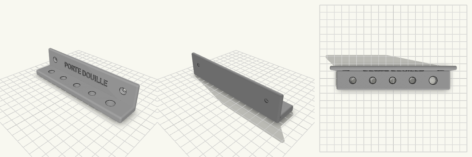
Support mural douilles 9 et 11 mm, 150×35
Support mural pour douilles (clé à cliquet) : plaque de fixation de 150 × 35 mm et tablette de 30 mm de profondeur. Quatre trous de 9 mm et un trou de 11 mm, répartis régulièrement sur 150 mm. Deux trous de fixation de 4,5 mm, fraisés, centrés au-dessus de la tablette. Texte « PORTE DOUILLE » gravé de 0,6 mm au fond de la tablette, contre la plaque. Arêtes arrondies à 2 mm. Mesure à vérifier avant impression : le diamètre réel de vos douilles. Les trous sont sans jeu ; prévoir 9,4 et 11,4 mm si l'ajustement est serré. Ne convient pas aux douilles de plus de 11 mm.
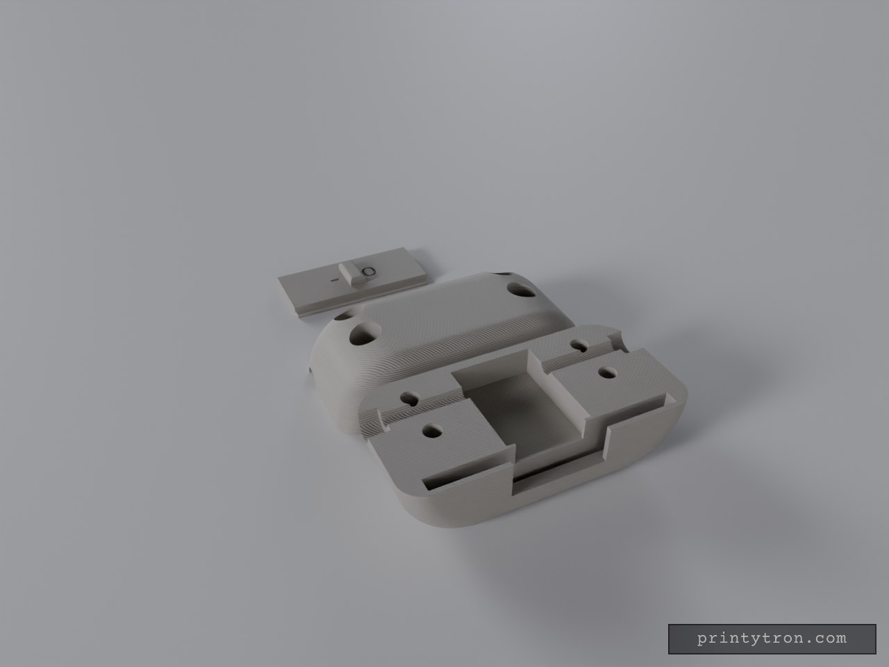
Oval Electrical Switch Housing with Slider
A pebble-shaped housing for a small electrical switch, built as two lengthwise half-ovals plus a separate sliding cover. The front and back halves split along the wire axis, and the seam runs through the middle of both 3 mm wire holes and the switch pocket. Lay the switch and wiring into one half, drop the sliding cover into the half-cut T-track, then close the other half over it like a clamshell. Four M3 screws pass through the back half and thread into M3 nuts seated in the front half from outside, so the seam clamps evenly and the two halves of the track stay aligned instead of catching the cover on a step. The housing is 54 × 27 mm in plan and 26.4 mm tall, with an 8 mm rounding on the bottom edge and 4.5 mm on the top so it reads as a pebble rather than a puck. Inside, the pocket is 15.9 × 11 × 20.2 mm — a 15.3 × 10.4 × 19.8 mm switch plus about 0.5 mm clearance per side. The sliding cover is 32 × 16.4 × 4 mm including its thumb tab and fills the full track width, travelling 14 mm. Its top is closed and trimmed to the housing's oval outline, so the outside reads as one continuous curved form; the 13.1 × 8.2 mm window is a blind recess on the underside with about 1 mm of skin above it. Slide the cover toward +X until the recess lines up with the opening to expose the switch, and back toward −X to close it. A small rectangular thumb tab, 3.6 mm along X and 8.2 mm across, sits at the cover's center and rises about 0.6 mm above the housing surface. Its top edges are rounded at 0.9 mm so it blends into the oval's curve, and its width matches the switch opening. Engraved marks 0.5 mm deep on the cover top indicate state within the exposed middle: "o" sits 4.2 mm on the +X side of the cover center and shows when closed; "-" sits 4.2 mm on the −X side and shows when open. Only one mark is visible at a time because the other slides under the roof. Both wire ports open into a 6 mm round seat, 6 mm long, ready for a wire holder of that size; the channels themselves stay at 3 mm. A roof spans the track from x = ±9 mm out to each end of the oval. It is part of the two housing halves and follows the oval's top curve, covering the track ends so no open slot shows there and closing the small triangular corner gaps. The cover runs under the roof, with its top about 0.2 mm below it; the middle section from x = −9 to +9 mm stays uncovered because the cover needs that clearance to move. The end stops are integrated into the two housing halves: each half carries its share of a stop at both ends of the track, and the stops fill the track's full cross-section, including the wide groove and neck, ending flush with the oval's outer surface. The cover is blocked at both ends of its travel and cannot slide out. To fit or remove the cover, open the halves as you would for the wires and switch. There are no separate loose stops left in the model. Fasteners and seam Four M3 screws, at x = ±17 mm and heights of 5 mm and 14 mm — solid body clear of the switch pocket and the wire channels. Use M3 × 18 mm; M3 × 20 mm also works, but its tip can poke through slightly. Back half (purple): 3.4 mm clearance holes through the wall, with 6.2 mm counterbores so the heads sit 6 mm in from the seam. Front half (blue): 3.4 mm screw holes run from the seam to a flat nut seat 9.8 mm out. The hex pockets are 6.5 mm across the corners and 4.2 mm deep for a standard M3 nut (5.5 mm across the flats). They open through the outer curved surface, so each nut drops in from outside and sits flush. The lower pockets are close to the bottom curve, so check that wall when you print. Print layout The three pieces are arranged side by side on the plate, not overlapping, so each can be exported on its own: Front Half (blue): 54 × 26.4 × 13.5 mm. The current plate keeps it split face up; with no pins on that face it can be flipped to sit split face down and print without supports. Back Half (purple): 54 × 26.4 × 13.5 mm, split face on the bed, so it needs no supports. Sliding Cover (orange): 32 × 16.4 × 4 mm, upright with its flat underside on the bed and the thumb tab on top. The fit has not been tested, so check the slide, the nut pockets and the screw alignment before a long print. Remix hooks Pocket — 15.9 × 11 × 20.2 mm. The first thing to re-cut for your own switch. Hold roughly 0.5 mm clearance per side: tighter grips it, looser lets it rattle. The 15.9 mm runs along X, so keep that orientation if the wires must stay in line with the cover. Split plane — along the wire axis. The seam runs through both 3 mm wire holes and the switch pocket. Moving it off-centre changes how the halves sit and where the wire seats land; keep the four screw holes aligned at x = ±17 mm, heights 5 mm and 14 mm. Screws and nuts — M3, 3.4 mm holes, 6.5 mm external hex pockets. Swap the external hex pockets for heat-set inserts or threaded bosses if you'd rather not handle loose nuts, or step down to M2.5 in the same bosses if 3 mm screws crowd the 27 mm width. Counterbore depth sets how far the heads sit in. Wire seats — 6 mm diameter × 6 mm long, feeding 3 mm channels. Resize these to match your actual wire holder, or turn them into a plain grommet relief if the wiring takes a different route. Sliding cover — 32 × 16.4 × 4 mm. It runs between the integrated stops and carries the blind 13.1 × 8.2 mm recess underneath. Lengthen or shorten the solid and recessed sections to change how far it travels before the switch is exposed; the current travel is 14 mm. Thumb tab — 3.6 × 8.2 mm, about 0.6 mm proud, with 0.9 mm rounded top edges. It must clear the roof ends at x = ±9 mm through the 14 mm travel. Changing its width, its rounding, or the roof span changes that clearance. Roof span — x = ±9 mm to the track ends. This sets how much of the track is covered and how much middle stays open. Raising or lowering the roof changes the cover's clearance and how flush its top sits; widening the exposed middle makes both marks visible at once. Integrated stops. They are cut into both halves at the ends of the track and fill the track cross-section, so changing the cover length means moving them rather than swapping a separate part. Shorten the cover instead if you want to keep the current stop positions. Oval body — 54 × 27 mm in plan, 26.4 mm tall. Stretch the oval along X to fit a deeper switch, and adjust the top and bottom edge roundings to change how soft or blocky it looks. Keep the wire-hole centreline in mind when moving the ends. Layout. Each piece keeps its own print orientation, so you can drop one piece or re-arrange the plate without touching the others. Variants worth trying Replace the "-" and "o" engravings with "OPEN" and "LOCK" lettering, or run a single indicator line across the cover. Add short alignment pegs beside the screws, or a tongue-and-groove along the seam, if the halves don't register well before tightening. Flatten one long side into a mounting tab with a screw hole so the housing can be fixed down. Print the cover in a contrasting colour to one or both halves so the split line and track read clearly.
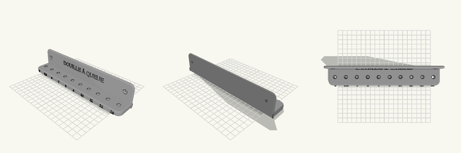
Support mural embouts 1/4" hexagonaux, douille à queue
Support mural pour embouts hexagonaux 1/4" (6,35 mm) et douilles à queue : plaque verticale de 48 mm de haut contre le mur, tablette horizontale de 10 mm d'épaisseur et 40 mm de profondeur. Ce qu'il accueille 10 empreintes hexagonales de 7 mm sur plats, espacées de 15 mm d'angle à angle Repères gravés en façade, de droite à gauche : 13, 12, 11, 10, 9, 8, 7, 6, 5,5, 5 Texte « DOUILLE À QUEUE » en relief sur la plaque, à 15 mm au-dessus de la tablette À vérifier avant impression Cote critique : 7 mm sur plats pour un embout de 6,35 mm, soit environ 0,65 mm de jeu Marge de 10 mm entre chaque extrémité et l'angle de la première ou dernière empreinte Ne convient pas Embouts de plus de 7 mm sur plats Fixation sans vis : deux trous fraisés sont prévus, vis non fournies
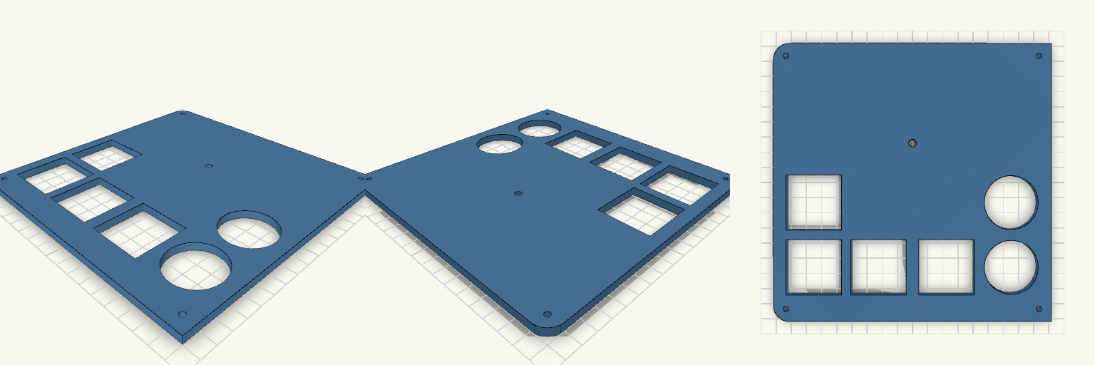
Tapa cuadrada con agujeros mixtos
Tapa de 180×180×5 mm con dos lados redondeados a la izquierda (radio 10 mm), cuatro agujeros M3 en las esquinas y un agujero de 5 mm. Dos agujeros redondos de 35 mm a la derecha y cuatro cuadrados de 36 mm a la izquierda, en la zona inferior. Ideas para remezclar Diámetro de los redondos (35 mm): súbelo o bájalo según la pieza que deba pasar; la pared entre ellos es de 7 mm. Lado cuadrado (36 mm): ajústalo por separado; los centros están a 42 mm. Radio de las esquinas (10 mm): 5 mm para una curva más suave. Agujero de 5 mm: está a 25,5 mm sobre el centro; muévelo para un pasacables o un pulsador. Combina con: una base o caja de 180 mm usando los M3 de las esquinas (3,4 mm, a 8 mm del borde).
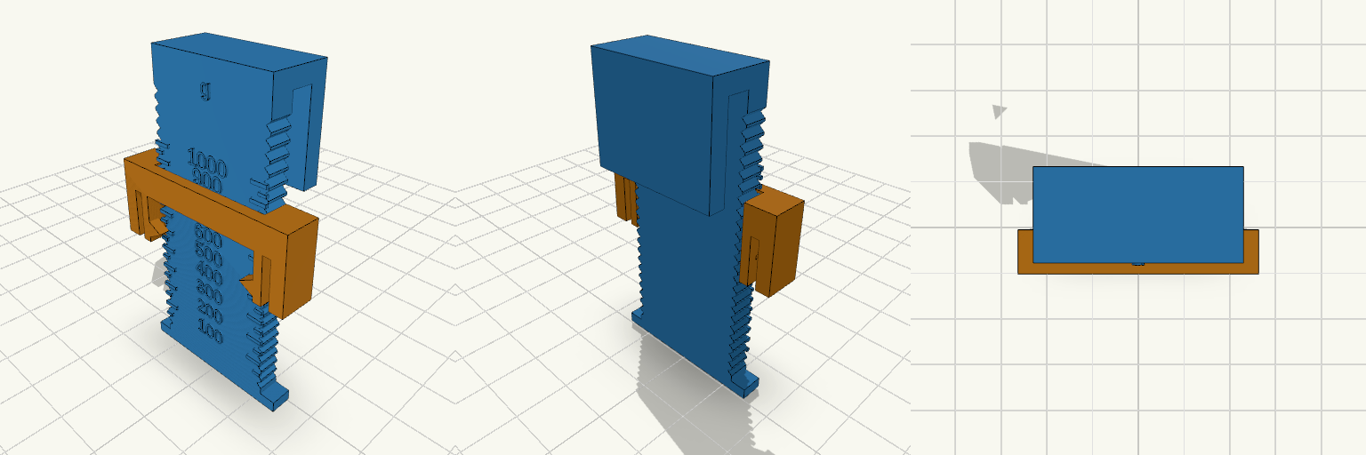
SpoolScope — Filament Remaining Gauge
SpoolScope is a two-part gauge for estimating how much filament remains on a standard spool, made for spools that sit out of easy view in an AMS or on a shelf. The rail hooks over the flange rim; the sliding block rides on it with light detents, so you can push it down until it touches the filament, lift the gauge away and read the result. Raised ticks and numbers plus an unambiguous arrow on the block make the measurement clear without needing line-of-sight while the gauge is in place. Features Two printed parts: a rail with a rim hook, and a detented sliding block. Gram scale from 0 to 1000 g, with ticks every 50 g and numbers every 100 g. Ticks follow filament geometry rather than an even spacing: closer together near full, wider apart near empty. Arrows on the block tip directly toward the scale, and the detents hold the reading after the gauge is lifted off. Hook gap of 4 mm, sized to clear flanges from 2.8 mm to 3.6 mm thick. Dimensions Flange diameter: 200 mm. Hub outer diameter: 95 mm (from a measured Polymaker spool). Full-roll diameter: 170 mm (estimated from a 1 kg PLA roll on a 95 mm hub and a 65.6 mm spool width). Hook gap: 4 mm. Fitting and calibration Sized around Polymaker and Inland 1 kg spools; other brands are worth checking against the hub and flange figures above. The scale can be shifted by a single fixed offset if a first print reads consistently high or low, so a weight check against a known spool is worth doing before trusting the numbers. If the error differs between a full and an empty spool, the hub and full-roll values are the ones to correct. Print notes Both parts are laid out flat on the print plate. The block contacts the filament at its outer edges rather than at the centre, so a reading can sit slightly high; a weight check against a known spool is the best way to confirm the scale.
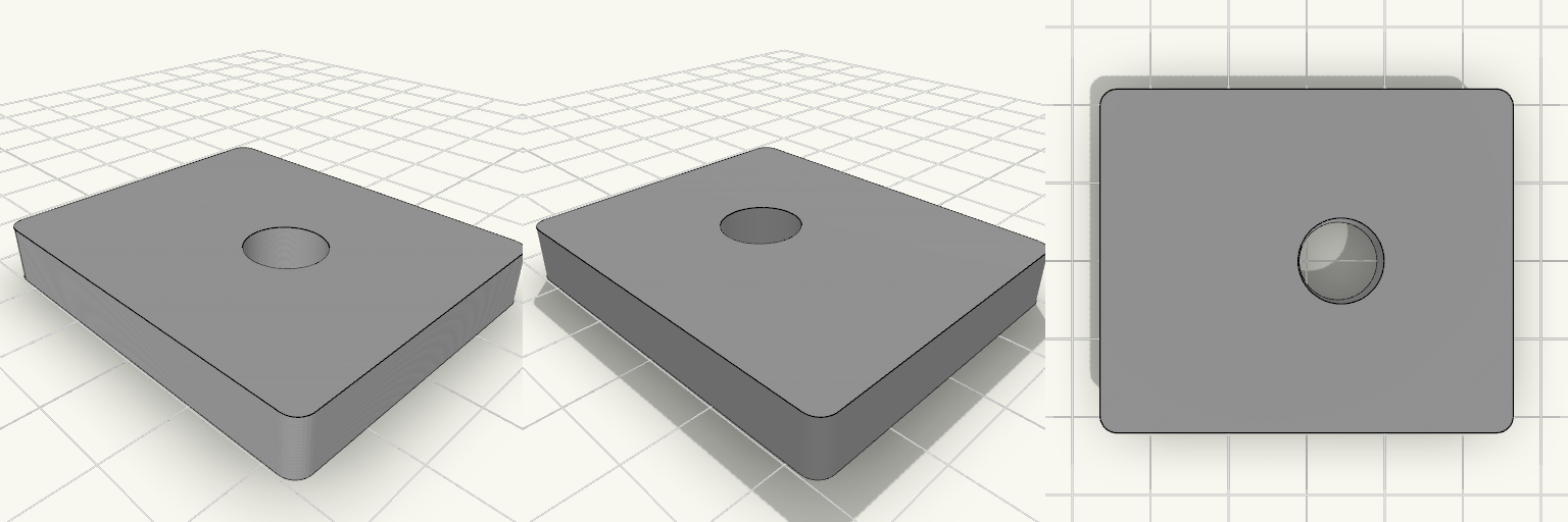
Elliptical Pedal Insert 48x40 Offset Hole
What it's for Central reinforcement insert for an elliptical trainer pedal, bonded into the damaged opening. Flat top, ribbed underside. Dimensions Base: 48 × 40 × 7 mm, rounded corners Through-hole: 10 mm, centered at 24 mm along the length and 4 mm toward the top edge from the width center 18 mm boss around the hole, 5 ribs to a 3 mm frame Remix ideas Change the hole offset for a different pedal Add or remove ribs Thicken the frame for heavier loads
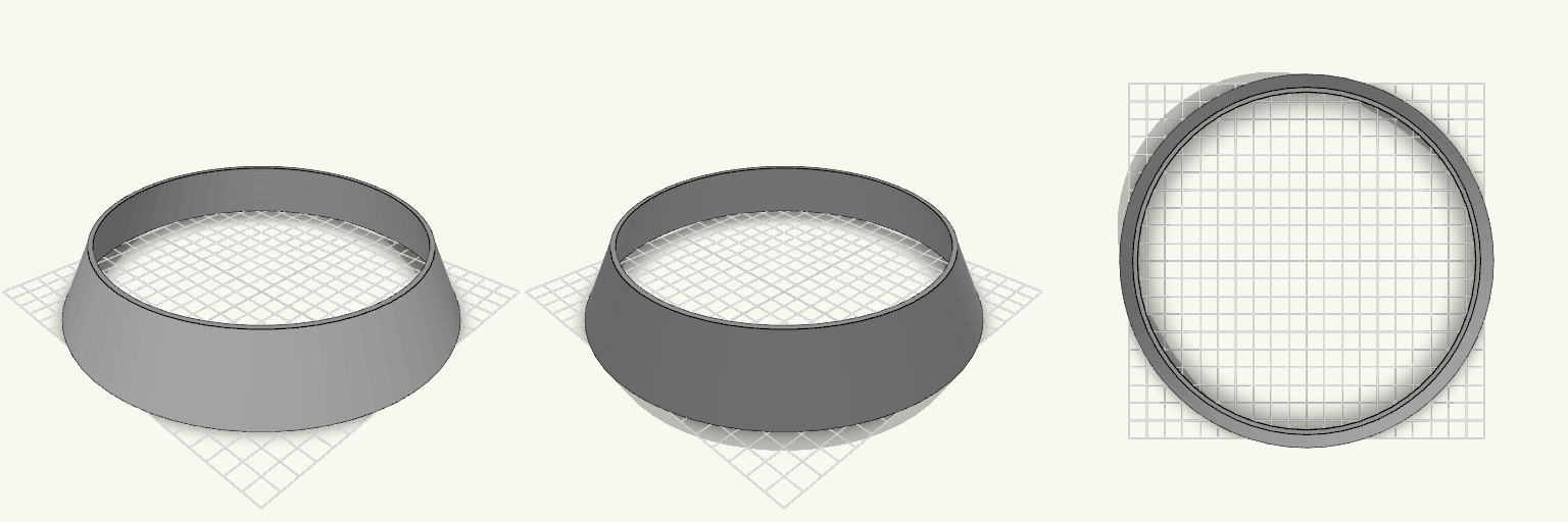
Rough Cone light diffuser
Two round openings that don't share a diameter is the small annoyance that stops everything downstream — the hose won't seat, the liner won't sit, the funnel wobbles instead of funnelling. This is the plain fix: a hollow truncated cone, wide at the bottom and narrow at the top, open at both ends so anything poured or pushed through it passes straight through instead of bottoming out. Fit dimensions Bottom outer diameter: 210 mm Top inner diameter: 170 mm Overall height: 38 mm Wall thickness: 2.4 mm Both ends open — it is a sleeve, not a capped cone Printing It prints as one piece sitting on its 210 mm base, so no assembly and no separate parts to line up afterwards. The wall is thin enough to stay flexible in the hand but still hold its shape, and the shallow flare means the outer surface is not a long unsupported overhang. Check the 170 mm top against whatever has to pass through it before printing — that is the number that decides whether the part works; the 210 mm bottom decides whether it sits down properly.
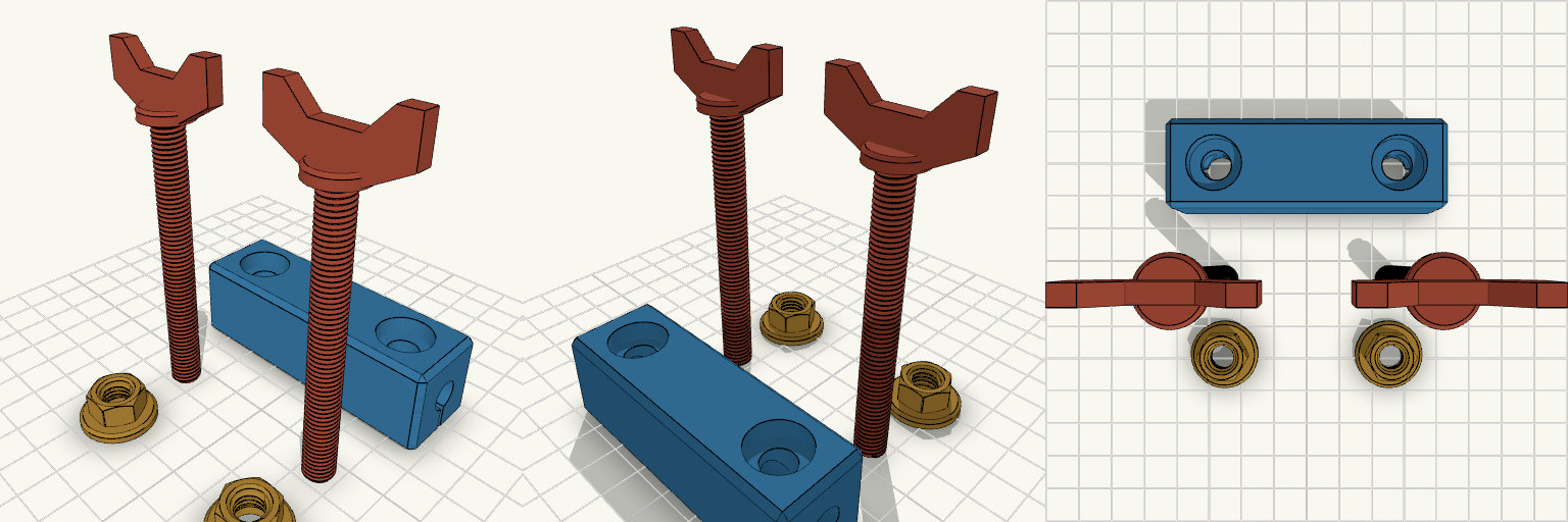
M8 Threaded Rod Clamp, 3 Inch
A clamp block that squeezes onto M8 threaded rod, with matching M8 × 1.25 wing screws and flanged nuts. The block is 76.2 mm (3 in) long and 24 × 24 mm in section, with an 8.4 mm bore running its full length; a slit through the lower half is closed by two screws at 25 mm either side of centre. It replaces a bought rod clamp and a pair of hand-tightened screws — everything on the plate is printed and then fitted together. Thread and fits M8 × 1.25 mm coarse thread throughout: the screw shank is threaded 8 mm, the nut bore carries the matching thread with 0.15 mm clearance so the pair turns together off the plate. Fine-pitch M8 × 1.0 will not match. M8 threaded rod, studding or 8 mm plain shaft in the bore. The bore is 8.4 mm with no give — measure your rod before printing. The flange pad under each nut has an 8.6 mm clearance hole, so only the hex section engages the thread and the pad bears flat on the work. The two bolt holes sit 50 mm apart (25 mm either side of centre, ±25 mm). Ordinary steel M8 × 1.25 hex screws and nuts will seat in the same counterbores and pockets if you would rather not print the hardware — though steel nuts come without the clamping pad, and the head counterbores are sized for hex heads, not the printed wing collars. What is on the plate Clamp Body — 76.2 × 24 × 24 mm, flat on the bed in the middle. M8 Screws — two off, each a 3 in (76.2 mm) threaded shank under a wing head: a round collar with two tapered wings, 34 mm tip to tip and 4 mm thick, about 92 mm overall. Laid out head up; the wings are flat plates, so if your slicer allows, stand each screw on its head with the shank up for the cleanest wing and thread. M8 Nuts — two off, each with a round 20 mm pad on its underside, 2.3 mm thick with a chamfered edge. Pads face the work when fitted. All pieces are separated with no overlaps, ready to print flat and assemble after. Check before printing The thread pair: matched at M8 × 1.25 but not test-fitted. If the printed screw and nut run too tight or too loose, the 0.15 mm clearance is the number to change. The screw length: a 3 in shank in the 24 mm block leaves about 52 mm of thread projecting below the body. Check that projection clears whatever sits under the clamp, and that the 34 mm wing head has room to turn once the thread is engaged. The 24 mm square section sets how far the clamp stands off its mounting surface — check it clears, and allow the 2.3 mm pad under each nut where the pad bears on the work. What it does not fit It is a rod clamp, not a nut clamp: it will not grip an M8 nut or bolt head in the bore. It does not suit 10 mm or 12 mm rod, and the bolt holes take M8 only — smaller screws will not seat in the counterbores or the nut pockets. Fine-pitch M8 × 1.0 hardware will not thread into these nuts. The pads are round, not square, and are sized only for the M8 pockets in this body.
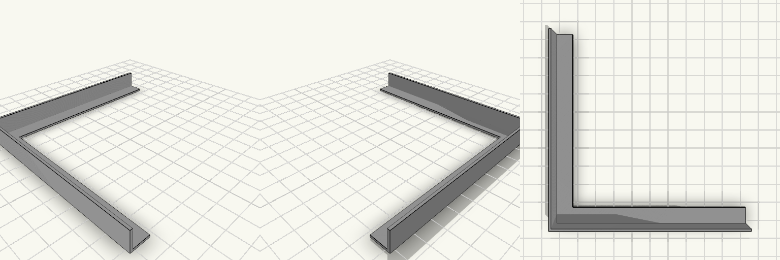
Canal en L con Paredes Altas
Una tira en L de 200 mm medidos por el centro, con dos brazos en ángulo recto, 10 mm de ancho y base de 1 mm. Las dos paredes exteriores, las más largas, se elevan 10 mm sobre la base y forman un canal de esquina abierto por dentro. Base: 1 mm de grosor Paredes exteriores: 1,2 mm de espesor, 10 mm por encima de la base Bordes interiores (más cortos): sin pared Altura total: 11 mm
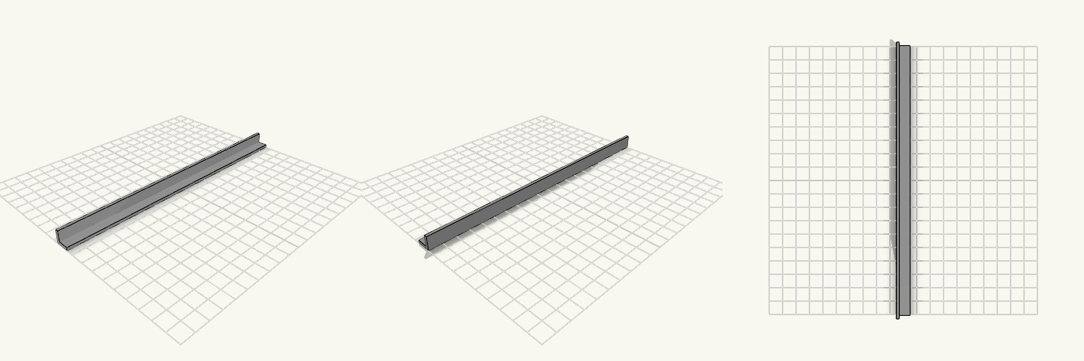
Ángulo — Tira en L de 20 cm
Ángulo — perfil en L de 20 cm de largo, pensado como esquinero, guía o refuerzo de bordes. Dos caras iguales a 90°, de sección sencilla y fácil de imprimir tumbado. Dimensiones Largo: 200 mm Ancho de cada cara: 10 mm Grosor: 2 mm Notas de impresión Imprimir apoyado sobre una cara, sin soportes. Para más rigidez, orientar las capas a lo largo del perfil.
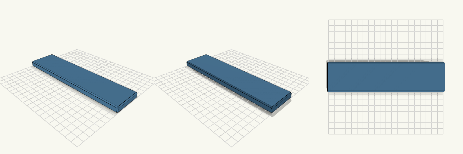
Placa Rectangular 200 x 50 x 10 mm
Placa rectangular maciza de 20 cm x 5 cm x 1 cm, para cuando hace falta una base plana y rígida que no se flexione ni se astille en los bordes. Datos para imprimir Medidas: 200 x 50 x 10 mm Bisel de 1,5 mm en todas las aristas, para que la primera capa no se levante en las esquinas Se imprime tumbada sobre su cara más grande, sin soportes Relleno recomendado: 20 % o más, según la carga
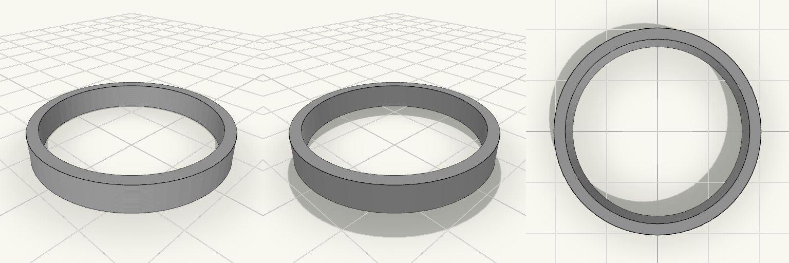
Кольцо 37/33 мм, толщина 5 мм
Простое круглое кольцо-втулка с ровными торцами. What it's for Прокладка, проставка, втулка или заготовка для переходного кольца. Печатается лёжа, без поддержек. Dimensions Наружный диаметр: 37 мм Внутренний диаметр: 33 мм Толщина стенки: 2 мм Высота (толщина кольца): 5 мм Remix ideas Добавить фаски на кромках. Увеличить внутренний диаметр на 0,2–0,4 мм для посадки с зазором. Добавить выступ или паз для фиксации.
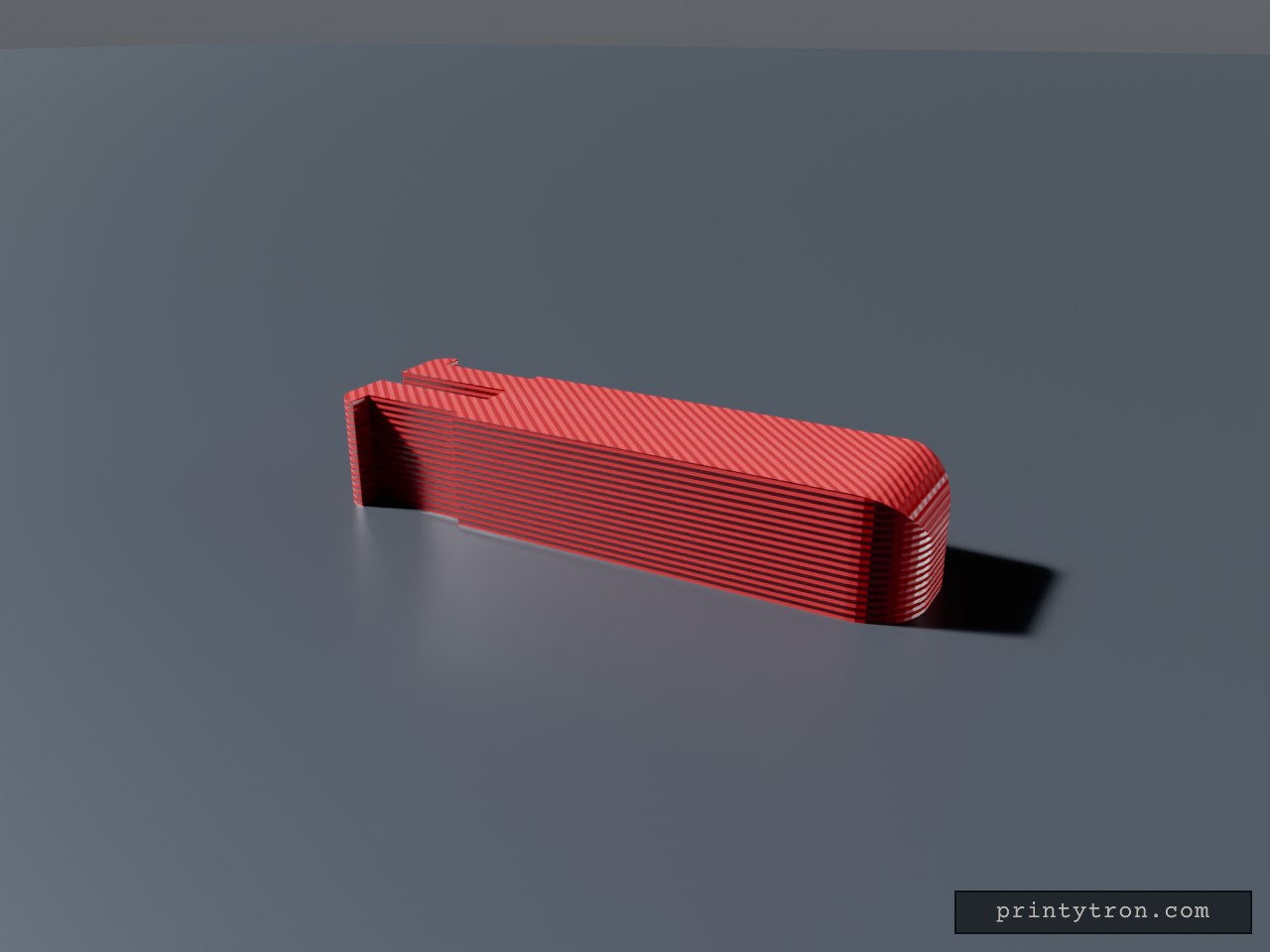
sink drain lever, G*b*rit
A small rectangular block, 26 mm overall, made of a 20 mm body and a 6 mm slotted end section. A narrow slot is cut into the 7.5 mm end face: 1.5 mm wide, running 6 mm into the length and through the full 5 mm height, so it reads as a thin open channel down that end. The slotted 6 mm keeps the full 7.5 mm width, while the rest of the body is narrowed to 6.5 mm, so a 1 mm shoulder sits on each side where the two sections meet. On the two flat side faces — not on the long corners — a straight rectangular step is cut 1 mm deep over the full 5 mm height. It starts 6 mm in from the slotted end and stops 1 mm short of the end face, so the last millimetre keeps its full width and a small square notch is left at the end. There is no angle anywhere in this cut. The far end from the slot is rounded: both vertical corners and the top edge there carry a 2.4 mm radius, blending into one soft rounded end — about as much as a 5 mm tall block can take before the curve meets itself halfway. The outer corners at the slotted end carry a small 0.9 mm radius; the side steps and the notch itself stay sharp, and the remaining top and bottom edges stay square. It works as a spacer, shim or register that a thin rib or plate edge drops into, with the side step giving that end a shoulder to seat against. Starting values Overall length: 26 mm — a 20 mm body plus the 6 mm slotted end section Body cross-section: 6.5 × 5 mm; the last 6 mm at the slotted end is 7.5 × 5 mm (1 mm shoulder each side) End slot: 1.5 mm wide, 6 mm deep along the length, through the full 5 mm height, centred Side steps: 1 mm deep on both flat side faces, constant depth, running full height, starting 6 mm from the end and ending 1 mm before the end face Far-end vertical corners and top edge: 2.4 mm radius, rounded Slotted-end outer corners: 0.9 mm radius; side steps and notch corners sharp Prints as one piece, no supports needed for any of the features above Remix hooks Body length is the free dimension. The 20 mm is the span between the rounded end and the start of the slotted section — stretch or shorten it to set the gap, and nothing else about the part has to change. The 6 mm slotted section is the fixed end, so all the length adjustment happens at the plain end. The width step is the fit dial. The 6.5 mm body and the 7.5 mm slotted end are two independent numbers: match the narrow body to the channel it slides into and the wider end to whatever it shoulders against. Equalising them removes the shoulder entirely and gives a plain constant-width block. Where the step falls. The 7.5 mm section currently runs the last 6 mm, tied to the slot depth; move that boundary to change how much of the part is full width. Slot width is the tightest tolerance. At 1.5 mm it takes a thin rib, sheet-metal edge or card; resize it to suit whatever it has to straddle, and remember a printed slot usually needs a little clearance over the nominal thickness. Slot depth sets the character. At 6 mm it is a deep open channel relative to the 26 mm part; shorten it to a millimetre or two and it becomes a shallow locating register instead. Side step depth. At 1 mm the relief is shallow and forgiving; go deeper for a part that shoulders harder against a pocket wall, or take it to zero for plain flat sides. The 1 mm land before the end face is what forms the notch — widen or remove it to change how the part locks against a shoulder. The far-end radius is already near its ceiling. 2.4 mm is close to the limit on a 5 mm block, so going rounder means growing the height, not the radius. Drop it to 1.5 mm for a snugger square look, or zero for a sharp end. Slotted-end radius is the tight one. 0.9 mm is limited by the short 1 mm end tab; widening that land is the way to buy room for a rounder corner there. Shape of the relief. Swapping the flat step for a ramp, or cutting the corners instead of the flat faces, turns this into a lead-in wedge or a chamfered block. Through vs. blind. The slot cuts the full height, so it is visible from both the top and bottom faces; make it blind and you get a closed-bottom channel. Obvious pairings. A matching 1.5 mm rib or plate edge for the slot to register against, or a mirrored second block so the two slots face each other and trap a thin part between them.
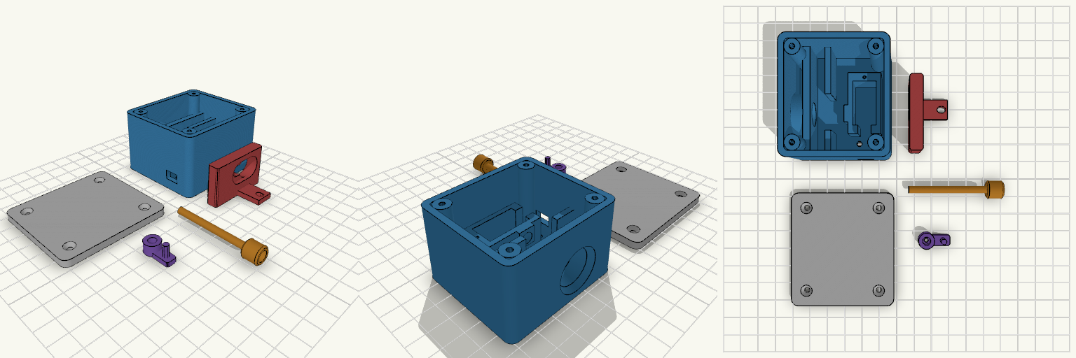
final cable lock sideways servo
Servo-operated cable lock for a paddleboard rental system, laid out as five separate printed parts: housing, service cover, release slide, cable unit and servo arm. The release slide prints top face down, so the yoke arm forms the first layers and needs no supports. The cable unit lies with its round head on the bed. Printer: Bambu Lab A1 mini, PETG or ASA Cable unit: 4 mm rod with 10 mm round terminal head and a magnet pocket in the tip Slide: 7 mm locking slot, 14 mm release hole, 9 mm travel Servo: 9 g micro servo, lead exits at the front end Export: set part to housing, cover, slide, cable or arm Untested: the design has not been load-tested and is not waterproof
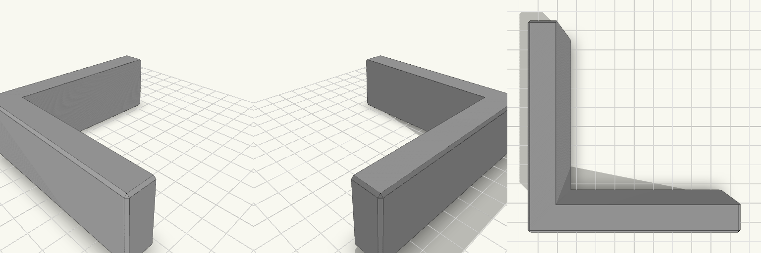
90 Degree Corner Clamping Jig
An L-shaped corner jig that holds two boards at a true 90 degrees while glue sets. It is made for picture frame joints, where a loose corner tends to drift into a parallelogram. Each arm has a channel that cradles a board up to 20 mm thick, and the two channels meet at a square inside corner. The 12 mm walls hold their shape under clamp pressure, and the outer edges are chamfered for a clean, easy-to-handle part. Fits stock up to 20 mm thick Square 90 degree inside corner 90 mm arms, 30 mm tall Clamp slots on each arm for squeezing the boards into the corner Flat base prints without supports Print it in PETG or PLA with several perimeters for stiffness. Keep glue off the channel walls, or line them with tape so the jig does not bond to the work.
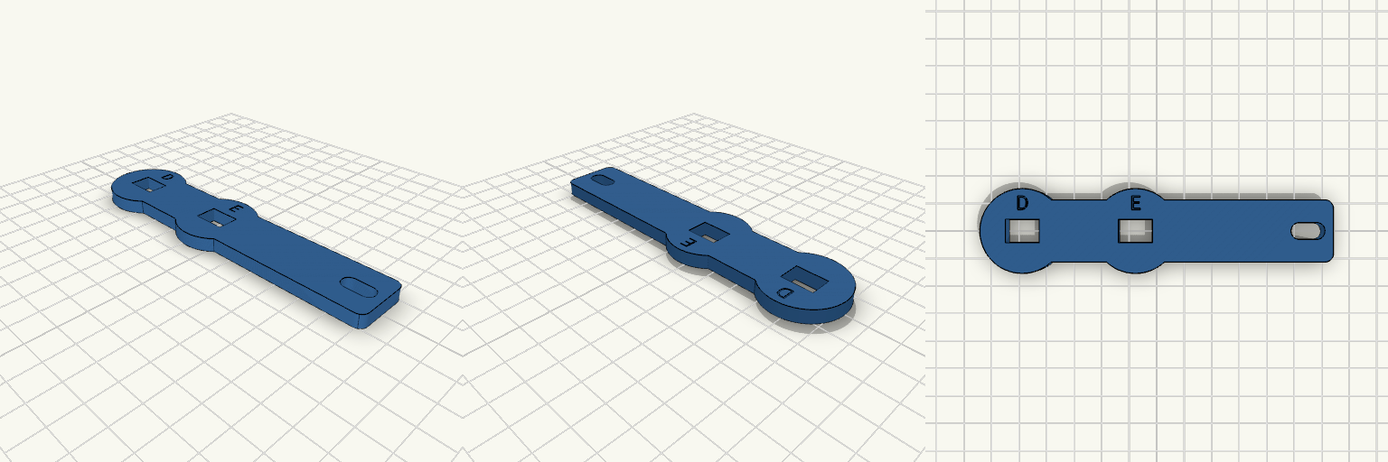
Industrial Flat-Plate Oxygen Cylinder Wrench
A flat, plate-style take on the Allied 66080 oxygen wrench, pared down to an industrial silhouette: twin round socket heads at one end, each stamped with its letter, and a chain slot at the tail. The D socket sits in the end head and the E socket in a second head beside it — both rectangular now, 12 mm along the wrench by 8.4 mm across, sized around the standard 5/16" spindle that D and E post valves share. The letters engraved on the top face above each socket are the only thing telling the two apart, which is exactly the point. The whole tool lives in a single 5 mm plate, 125 × 30 mm, so it lies flat in a pocket or a kit bag and prints as one piece with nothing to assemble. Design notes D socket: end head, 12 × 8.4 mm rectangle, letter engraved on the top face above it. E socket: second round head alongside, same 12 × 8.4 mm rectangle, its own engraved letter. Chain slot: oblong, 12 × 6 mm with rounded ends at the tail, sized for a chain or lanyard. Flat plate body: 125 × 30 × 5 mm overall, no supports needed through the flat sections. Open-end jaw: removed to make room for the second head, leaving a clean two-socket profile. Thread a chain or lanyard through the tail slot and the wrench stays with the cylinder instead of wandering off between refills — the optional chain is the small detail that keeps the tool where it's needed. Both sockets are built to the standard 5/16" spindle rather than a specific drawing, and the 12 mm socket length is an approximation, so measure a valve flat-to-flat before leaning on the fit.
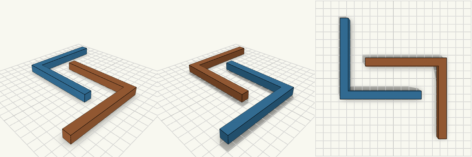
living room plinth
Two 100 × 100 mm L-sections, 10 mm leg width and 10 mm thick, laid flat and nested together to save print-bed space. Fit and layout One piece sits normally; the other is flipped onto its back and turned so the two interlock with a 1 mm gap. Combined footprint: about 111 × 111 mm. Check before printing: the 1 mm gap needs a bed that prints cleanly at that spacing; widen it if the pieces fuse. Not a fit for beds under 115 mm square.
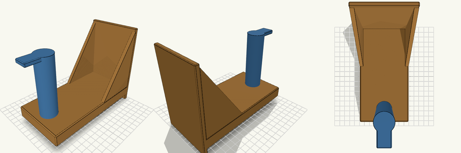
Stovas su vienpuse 10 cm iškyša
Stovas su sulietu 29 mm strypu, kuris kyšo 100 mm į vieną pusę. Strypo gale yra stačiakampis stabdiklis, kad kabinamas daiktas nenuslystų. Ką verta keisti Stabdiklio aukštis: 20 mm virš strypo paviršiaus (iš viso 34,5 mm nuo ašies). Stabdiklio plotis: 20 mm, storis 6 mm. Strypo ilgis ir skersmuo: 100 mm, 29 mm. Pagrindas: 90 mm plotis, 140 mm gylis, dvi trikampės atramos 105 × 70 mm. Tinka poroms su kitu stovu, jei strypą reikia perdaryti į atskirą detalę.
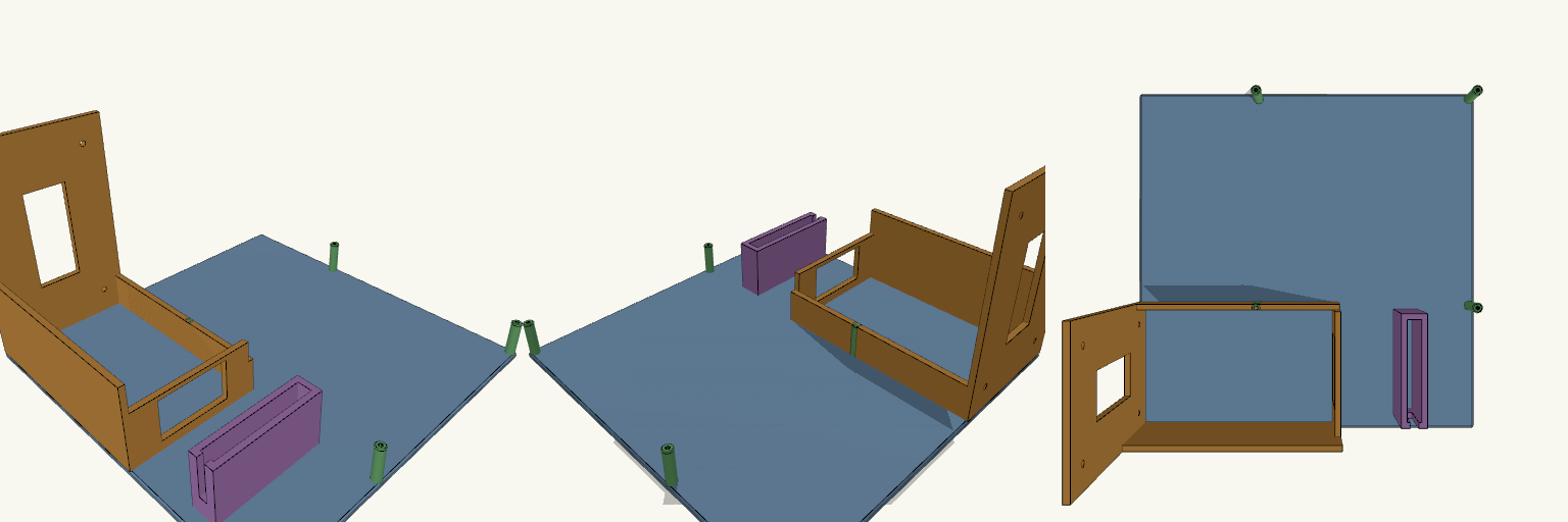
One-Piece Open-Frame PC Test Bench
A single-piece open-frame test bench base sized at 250 x 250 mm to fit a 256 x 256 mm print bed, with a 4 mm thick base plate for stiffness in PLA. The PSU sits on its side in a tight pocket with 4 mm retaining walls and a rear bracket drilled with four screw holes plus a port opening. Four 25 mm standoffs carry a Micro-ATX board, and a narrow upright slot holds a 2.5-inch SSD. Base plate: 250 x 250 x 4 mm, chamfered edges PSU pocket: 140.4 x 86.2 mm, 4 mm walls, rear bracket with 4 x 4.2 mm holes Standoffs: 4 x 25 mm high, 2.9 mm pilot holes for M3 screws SSD slot: 10 mm gap, 70.8 mm long, with a cable notch Open frame for airflow and easy access
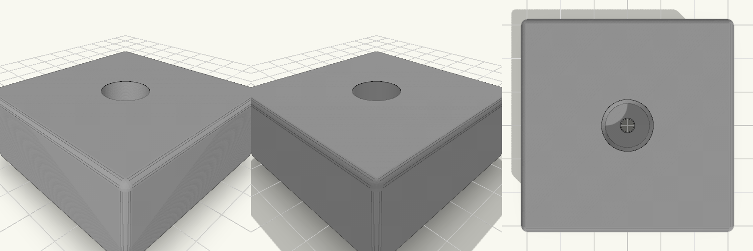
Quadratplatte mit Stufenloch
Eine kompakte, quadratische Block-Platte mit sauber abgerundeten Außenkanten und einem mittigen Stufenloch – wie eine kleine Senkung für Schraubenköpfe oder Magnete, nur eben tiefer. Einteilig, ohne Montage druckbar. Grundmaß: 50 × 50 × 20 mm Stufenloch von unten: Ø4 mm über 8 mm, danach Ø12 mm über 12 mm Außenkanten: 1,5 mm Radius Lochkanten: nicht gebrochen
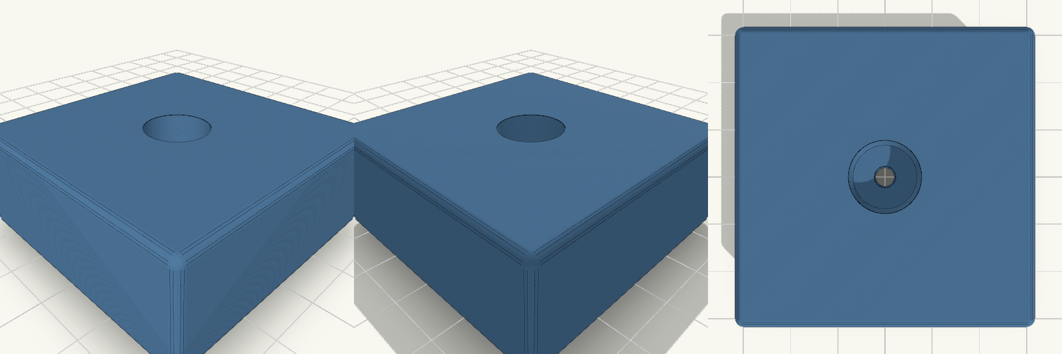
Platte Laterne 10mm Lochtiefe
Quadratische Platte 50 × 50 × 20 mm mit mittigem Stufenloch, damit ein Schraubenkopf oder Bund bündig versenkt sitzt und nicht herausrutscht. Grundmaß: 50 × 50 × 20 mm Stufenloch von unten: Ø4 mm über 10 mm, danach Ø12 mm über 10 mm Außenkanten: 1,5 mm Radius, Lochkanten scharf Druck: Unterseite nach unten, ohne Stützen, einteilig
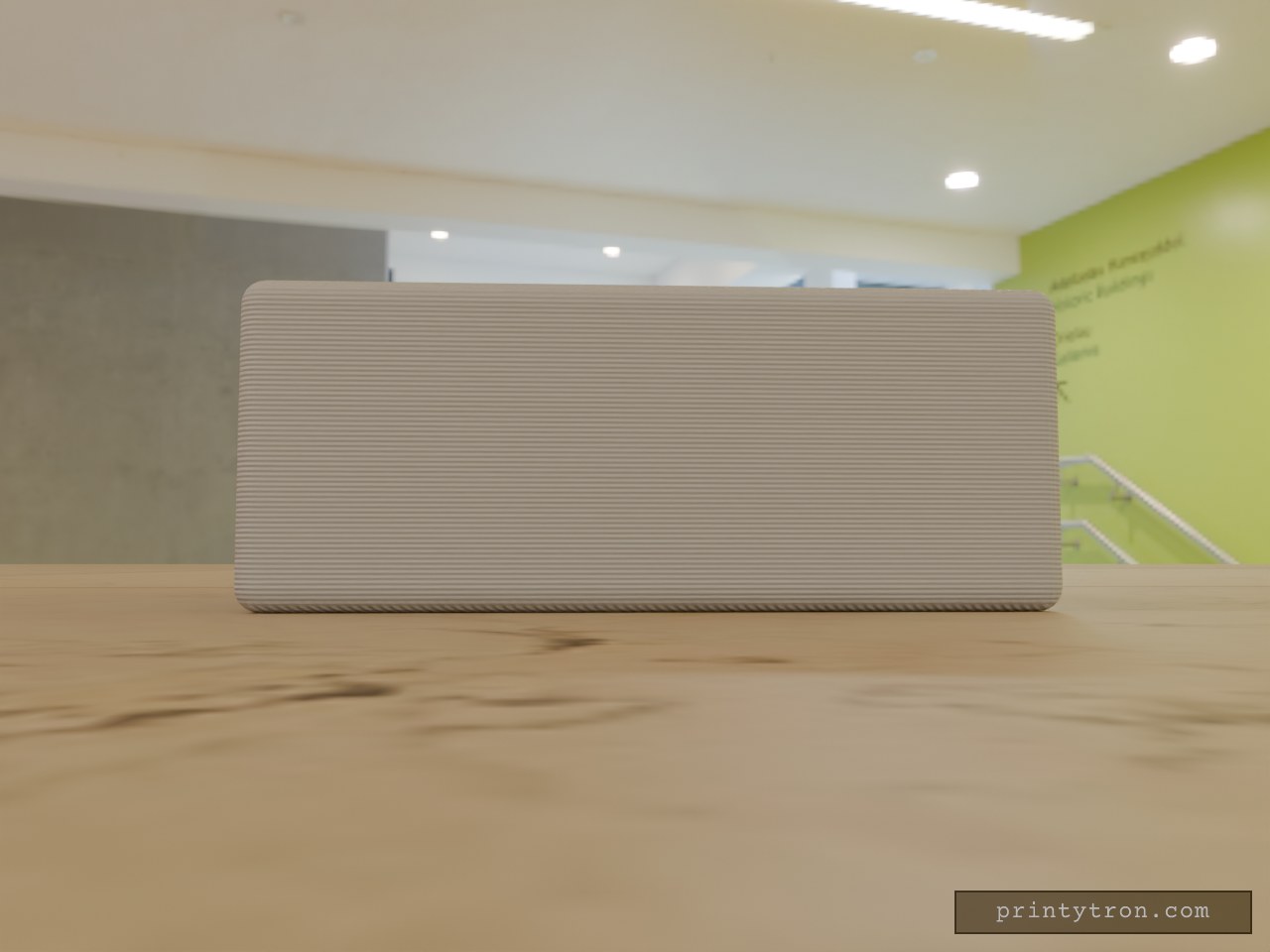
Platte Laterne
Eine quadratische Platte mit 50 × 50 mm Grundfläche und 20 mm Dicke. Mittig sitzt ein Stufenloch, von der Unterseite gemessen: Auf den ersten 8 mm beträgt der Durchmesser 4 mm, auf den folgenden 12 mm 12 mm. Die Außenkanten sind mit 1,5 mm Radius abgerundet, die Lochkanten sind nicht gebrochen. Grundmaß: 50 × 50 × 20 mm Mittiges Stufenloch: Ø4 mm über 8 mm Tiefe, danach Ø12 mm Außenkanten: 1,5 mm Radius Lochkanten: nicht abgerundet Ausführung: einteilig, keine Montage nötig
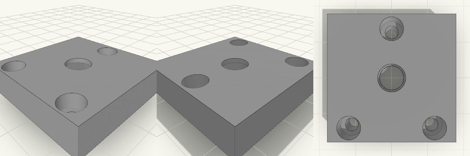
30x30x8mm Interposer Plate, 1/4-20 Nut Pocket
Square-edged 30x30x8 mm interposer plate with a central 6.6 mm hole for a 1/4-20 stud. A hex pocket for a 1/4-20 nut is enclosed inside the plate and is designed for a mid-print pause: the nut is inserted when the print reaches the top of the pocket, and the remaining layers bridge over it. Plate: 30 x 30 x 8 mm, square edges Center hole: 6.6 mm through, for a 1/4-20 stud Nut pocket: 13.2 mm across corners (about 11.4 mm across flats), 5.8 mm deep, from Z 1.0 to 6.8 mm Pause height: Z = 6.8 mm, then resume to print a 1.2 mm cover Screw holes: three 3.3 mm holes with 5.6 mm counterbores from the top face, 3.5 mm deep Triangle pattern: apex 3.5 mm from the back edge, two front holes 20 mm apart Nut size assumed: standard 7/16 in across flats, 7/32 in thick
Need a part that doesn't exist yet?
Start building →