Aerodynamic Twin-Duct Fan Splitter
Created today
Description
A dedicated airflow splitting manifold engineered to channel output from a standard 120mm cooling fan into twin 60mm cylindrical ducts. The system features an aerodynamic internal Y-wedge to evenly distribute incoming air left and right, ensuring minimal turbulence and balanced static pressure.
Design Features
- Modular 3-Piece Build: Prints as an independent center distributor and two identical 190mm slip-fit extension arms.
- Integrated Venting: Each 60mm diameter arm includes three evenly spaced 12mm exhaust ports along its lower centerline.
- Exact Fitments: The center unit handles a standard 120mm case fan, complete with correctly spaced mounting points, while robust male collars provide tight, removable connections to the extension ducts. Total assembled span reaches precisely 500mm.
Photos
Technical views
More like this
Explore more in Workshop & Tools →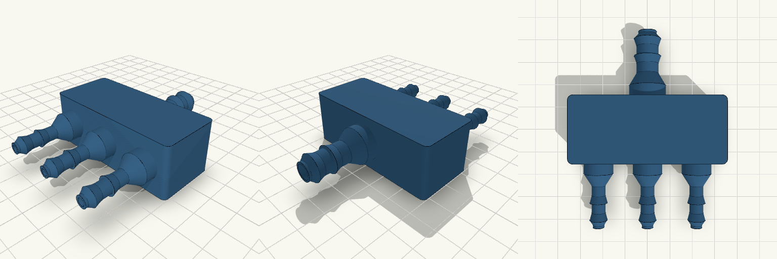
Robust 3-Way Irrigation Manifold
A heavy-duty 1-to-3 splitter manifold designed for 5 mm ID irrigation hose. It prints completely flat on its base without supports, using teardrop-shaped mounting bosses to bridge the overhangs. To meet the structural requirement of 4 solid perimeters on a 5.4 mm outer barb, the internal channel strictly inside the hose stems necks down to 2.6 mm. Inside the thick bosses and the main manifold body, the passages open up to 5 mm and 7 mm respectively to minimize flow restriction. Remix Hooks Barb Spacing & Count: Adjust the port_solid() module to add more barbs or change the spacing for stiffer tubing. Port Layout: Expand the main body length and loop the for(x = ...) call to add 4, 5, or 6 outlets. Mounting: The flat rectangular body leaves plenty of room to cut countersunk screw holes if you need to hard-mount it to a rail or planter box.
Biofloc Monitor Station Enclosure
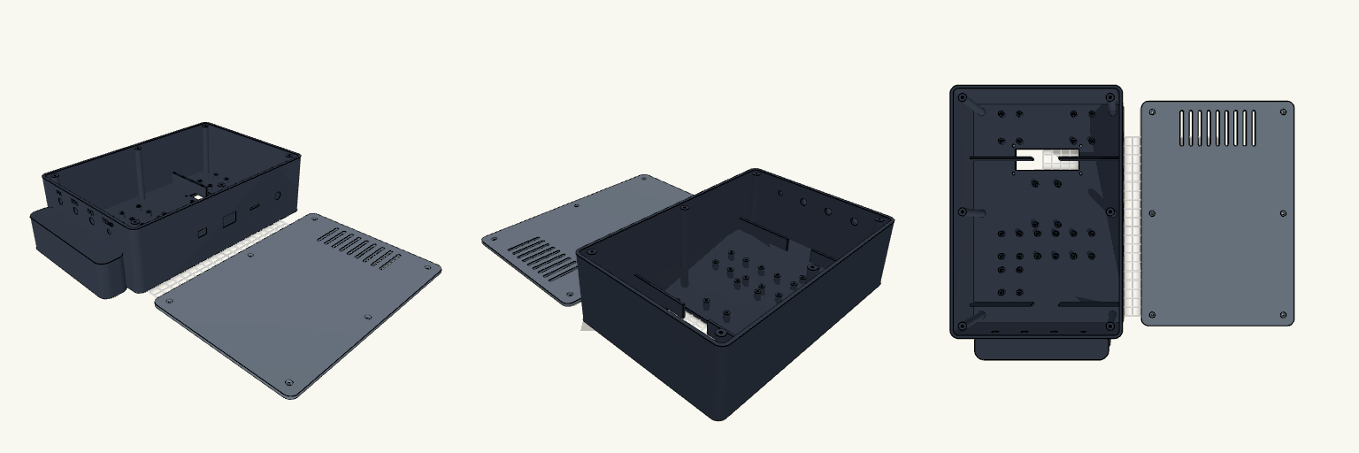
An enclosure is only as good as the snarl of wires it prevents. This is a heavy-duty two-part monitor housing built specifically for FDM printing, designed to group, separate, and anchor a complete suite of biofloc water-quality electronics without turning into a bird's nest inside. The layout isolates the battery compartment at the bottom and keeps the DC buck converters and relay in a ventilated top section, leaving the central deck clear for the ESP32 and an array of sensor interfaces. Internal divider walls double as cable routing channels, forcing the wiring to stay orderly. Core Features Printability: Both halves print completely flat on the build plate (Z=0). The integrated bottom handle is flush with the front face to avoid overhangs. Dimensions: 170 mm width × 250 mm height × 75 mm depth. Hardware Required: 6× M3 screws for the rear cover; additional M3 hardware for the internal standoffs and the 16x2 LCD faceplate mount. Ports: Bottom panel holds 4× sensor ports (3× 8mm, 1× 6mm) with engraved labels. Right panel holds cutouts for 12V DC, an SD card slot, a rocker switch, and USB programming access.
Modulær Vandmodstands-Blok
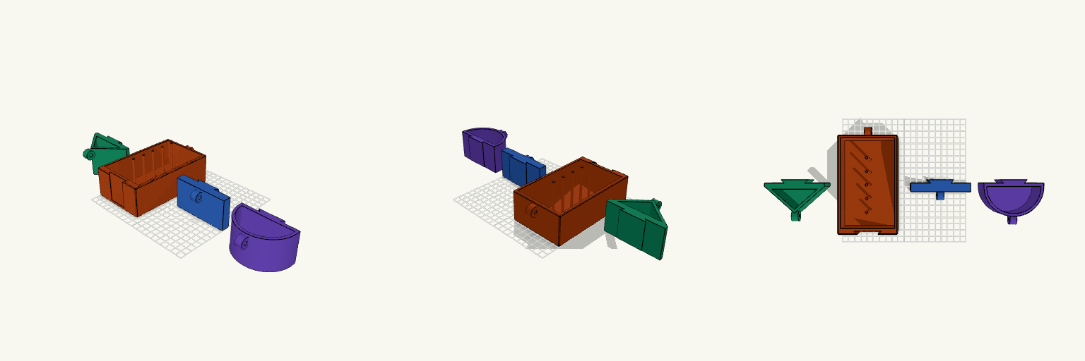
Et modulært testsystem til at måle vandmodstand ("bluff body"-træk). Hovedskroget fungerer som en tung ballastkasse med master i bunden, der lader dig justere vægten ved at placere standard fysiklodder. Udskiftelige frontplader gør det nemt at isolere formfaktorens betydning for modstanden. Dette design er tænkt som et udgangspunkt for at teste forskellige stævnprofiler: Modulær front: Svalehalesporet lader dig nemt slibe eller designe nye frontprofiler uden at skulle printe hele skroget igen. Justerbar dybgang: Masterne (3.9 mm i diameter, 20 mm afstand) er lavet specielt til standardlodder — tilføj eller fjern lodder for at ændre tyngdepunktet. Trækpunkter: Øjerne er placeret 10 mm fra toppen, så din snor kører lige ved vandlinjen i et fyldt kar.
Fillable Ballast Flag Base
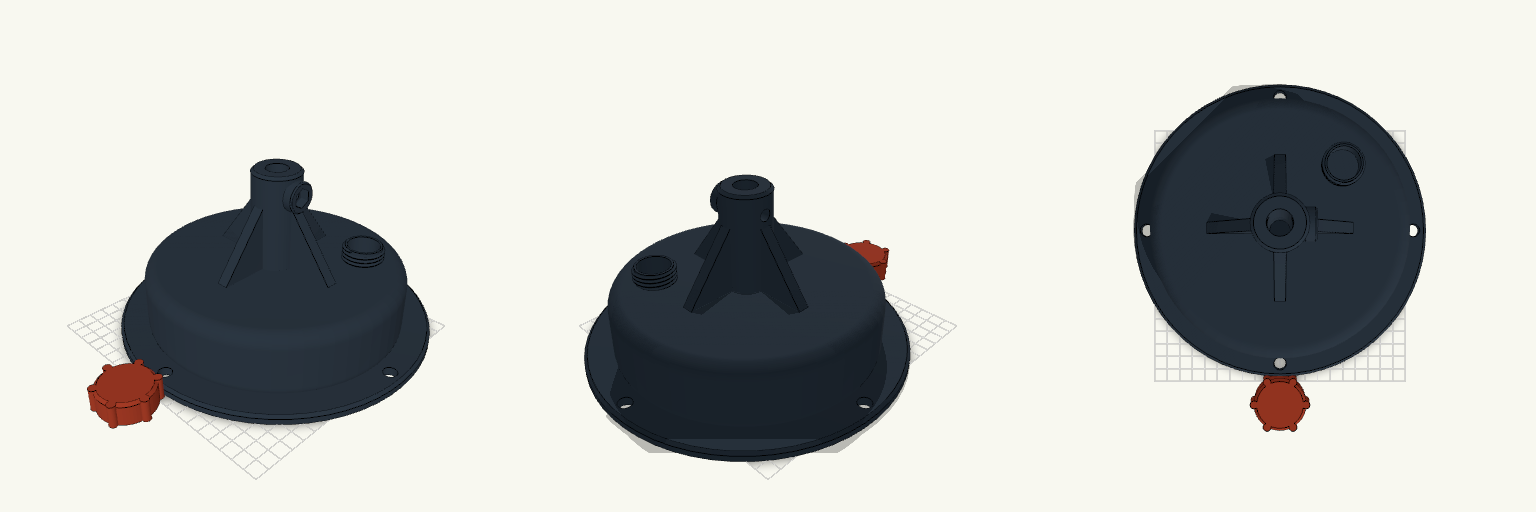
A freestanding, FDM-printable flag base designed for securing ground stakes indoors or on hard surfaces. The primary body features a hollow dome for sand ballast, accessed via a robust threaded fill port, and an integrated flange with four mounting holes for temporary pegging or bolting. A reinforced 120mm central socket holds the stake, braced by four solid corner ribs. The socket includes a side-entry hex nut trap designed for an M8 bolt to clamp the stake firmly in place without play. Ballast capacity: ~1.3 Liters (approx. 2kg of dry sand). Hardware required: 1x M8 bolt (25-30mm long), 1x M8 hex nut. Compatibility: Clears a 16mm standard tent or feather flag stake (socket bore is 16.5mm). Overall print dimensions: 230mm footprint diameter, 120mm height. Fits most mid-sized print beds.
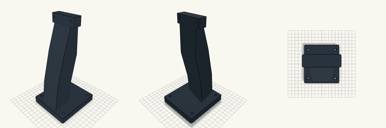
Measure Stand
An arced 220mm-tall mounting stand for a measurer. Built with a solid base that secures to a desk and a precisely measured top block engineered for bolt-through attachment.
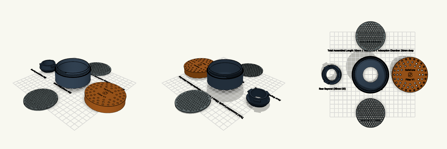
Experimental Filter Housing V1
A multi-part FDM-optimized housing for testing granular and particulate filter media. Designed with discrete chambers, retaining grids, and standard O-ring sealing surfaces. Disclaimer: This is a strictly non-certified prototype for experimental projects. Do not use for certified respiratory protection. What it's for Testing layered filtration concepts. The housing accommodates a 26mm deep granular adsorption bed and an 8–10mm particulate filter section, separated by an air-distribution spacer. Media is retained by drop-in mesh grids, allowing rapid replacement during testing. Dimensions Overall Assembled Size: 80 mm diameter × 55 mm length Wall Thickness: 3 mm main shell Adsorption Chamber: 68 mm ID × 26 mm depth Connections: Rear standard 3-tab quarter-turn bayonet (35 mm OD tube) Print notes Orientation: Parts are laid out flat on the bed. The front cap should be flipped 180° in your slicer so its top face rests on the build plate. Supports: None required. The bayonet tabs are modeled with a 45° chamfer profile to print cleanly without support material. Tolerances: Threaded interfaces are built with 0.5–1mm diametrical clearances to accommodate standard PETG shrinkage.