Brutalist Framing Outer Clamp
Created 3 months ago
Description
A monolithic, brutalist-inspired L-block designed to enforce exact ninety-degree angles on unruly lumber. Engineered specifically to cure the dreaded parallelogram effect in picture framing, this outer squaring jig cradles two boards firmly against its orthogonal walls while the glue sets.
Design Notes:
- Oversized Clamp Cutouts: Generous 44mm slots on each arm easily accommodate standard bar clamps.
- Glue Relief Vertex: A central circular cutout ensures escaping squeeze-out never fuses the project to the jig.
- Rigging Anchor: A central tie-down hole offers a secondary strap point for complicated assemblies.
Photos
Technical views
More like this
Explore more in Workshop & Tools →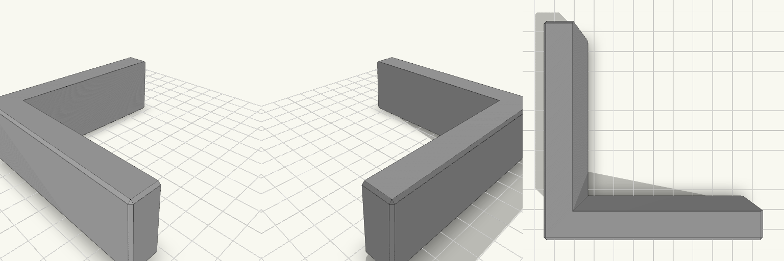
90 Degree Corner Clamping Jig
An L-shaped corner jig that holds two boards at a true 90 degrees while glue sets. It is made for picture frame joints, where a loose corner tends to drift into a parallelogram. Each arm has a channel that cradles a board up to 20 mm thick, and the two channels meet at a square inside corner. The 12 mm walls hold their shape under clamp pressure, and the outer edges are chamfered for a clean, easy-to-handle part. Fits stock up to 20 mm thick Square 90 degree inside corner 90 mm arms, 30 mm tall Clamp slots on each arm for squeezing the boards into the corner Flat base prints without supports Print it in PETG or PLA with several perimeters for stiffness. Keep glue off the channel walls, or line them with tape so the jig does not bond to the work.
M8 Threaded Rod Clamp, 3 Inch
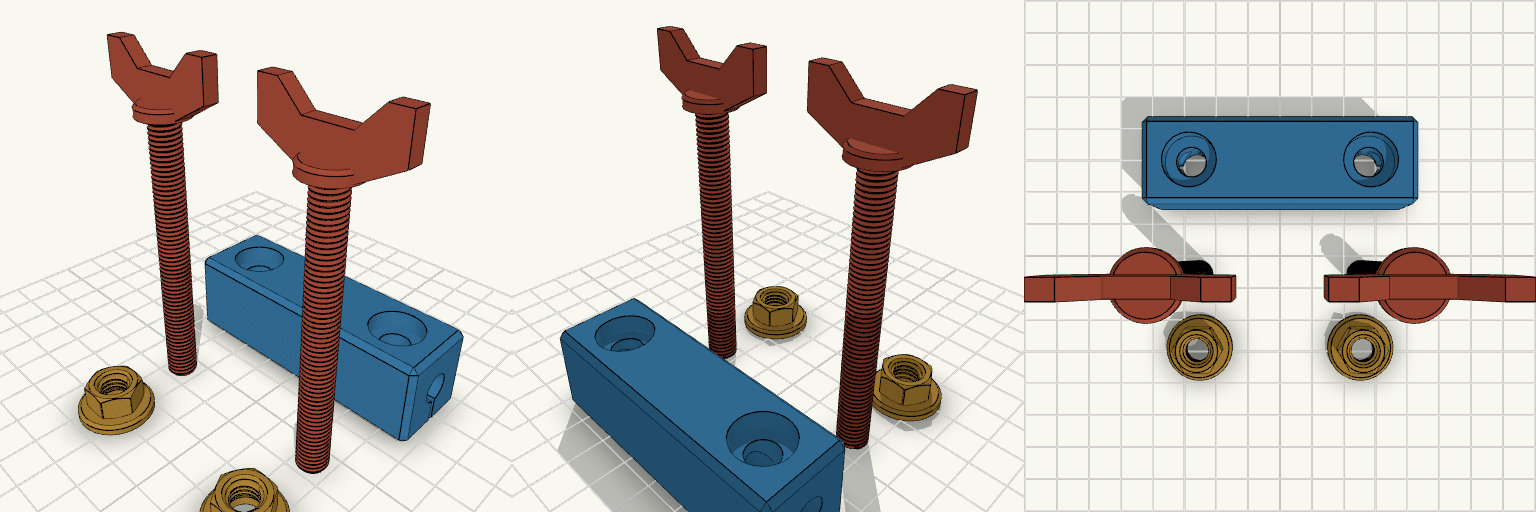
A clamp block that squeezes onto M8 threaded rod, with matching M8 × 1.25 wing screws and flanged nuts. The block is 76.2 mm (3 in) long and 24 × 24 mm in section, with an 8.4 mm bore running its full length; a slit through the lower half is closed by two screws at 25 mm either side of centre. It replaces a bought rod clamp and a pair of hand-tightened screws — everything on the plate is printed and then fitted together. Thread and fits M8 × 1.25 mm coarse thread throughout: the screw shank is threaded 8 mm, the nut bore carries the matching thread with 0.15 mm clearance so the pair turns together off the plate. Fine-pitch M8 × 1.0 will not match. M8 threaded rod, studding or 8 mm plain shaft in the bore. The bore is 8.4 mm with no give — measure your rod before printing. The flange pad under each nut has an 8.6 mm clearance hole, so only the hex section engages the thread and the pad bears flat on the work. The two bolt holes sit 50 mm apart (25 mm either side of centre, ±25 mm). Ordinary steel M8 × 1.25 hex screws and nuts will seat in the same counterbores and pockets if you would rather not print the hardware — though steel nuts come without the clamping pad, and the head counterbores are sized for hex heads, not the printed wing collars. What is on the plate Clamp Body — 76.2 × 24 × 24 mm, flat on the bed in the middle. M8 Screws — two off, each a 3 in (76.2 mm) threaded shank under a wing head: a round collar with two tapered wings, 34 mm tip to tip and 4 mm thick, about 92 mm overall. Laid out head up; the wings are flat plates, so if your slicer allows, stand each screw on its head with the shank up for the cleanest wing and thread. M8 Nuts — two off, each with a round 20 mm pad on its underside, 2.3 mm thick with a chamfered edge. Pads face the work when fitted. All pieces are separated with no overlaps, ready to print flat and assemble after. Check before printing The thread pair: matched at M8 × 1.25 but not test-fitted. If the printed screw and nut run too tight or too loose, the 0.15 mm clearance is the number to change. The screw length: a 3 in shank in the 24 mm block leaves about 52 mm of thread projecting below the body. Check that projection clears whatever sits under the clamp, and that the 34 mm wing head has room to turn once the thread is engaged. The 24 mm square section sets how far the clamp stands off its mounting surface — check it clears, and allow the 2.3 mm pad under each nut where the pad bears on the work. What it does not fit It is a rod clamp, not a nut clamp: it will not grip an M8 nut or bolt head in the bore. It does not suit 10 mm or 12 mm rod, and the bolt holes take M8 only — smaller screws will not seat in the counterbores or the nut pockets. Fine-pitch M8 × 1.0 hardware will not thread into these nuts. The pads are round, not square, and are sized only for the M8 pockets in this body.
Tapa cuadrada con agujeros mixtos
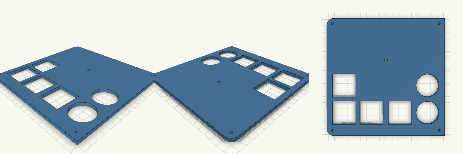
Tapa de 180×180×5 mm con dos lados redondeados a la izquierda (radio 10 mm), cuatro agujeros M3 en las esquinas y un agujero de 5 mm. Dos agujeros redondos de 35 mm a la derecha y cuatro cuadrados de 36 mm a la izquierda, en la zona inferior. Ideas para remezclar Diámetro de los redondos (35 mm): súbelo o bájalo según la pieza que deba pasar; la pared entre ellos es de 7 mm. Lado cuadrado (36 mm): ajústalo por separado; los centros están a 42 mm. Radio de las esquinas (10 mm): 5 mm para una curva más suave. Agujero de 5 mm: está a 25,5 mm sobre el centro; muévelo para un pasacables o un pulsador. Combina con: una base o caja de 180 mm usando los M3 de las esquinas (3,4 mm, a 8 mm del borde).
SpoolScope — Filament Remaining Gauge
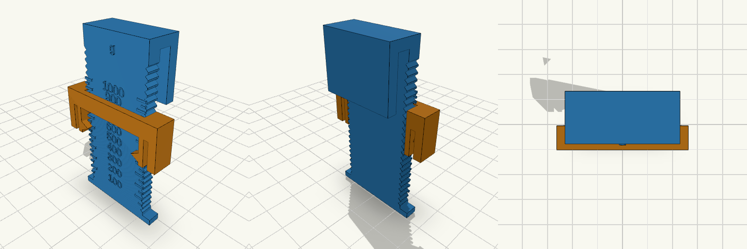
SpoolScope is a two-part gauge for estimating how much filament remains on a standard spool, made for spools that sit out of easy view in an AMS or on a shelf. The rail hooks over the flange rim; the sliding block rides on it with light detents, so you can push it down until it touches the filament, lift the gauge away and read the result. Raised ticks and numbers plus an unambiguous arrow on the block make the measurement clear without needing line-of-sight while the gauge is in place. Features Two printed parts: a rail with a rim hook, and a detented sliding block. Gram scale from 0 to 1000 g, with ticks every 50 g and numbers every 100 g. Ticks follow filament geometry rather than an even spacing: closer together near full, wider apart near empty. Arrows on the block tip directly toward the scale, and the detents hold the reading after the gauge is lifted off. Hook gap of 4 mm, sized to clear flanges from 2.8 mm to 3.6 mm thick. Dimensions Flange diameter: 200 mm. Hub outer diameter: 95 mm (from a measured Polymaker spool). Full-roll diameter: 170 mm (estimated from a 1 kg PLA roll on a 95 mm hub and a 65.6 mm spool width). Hook gap: 4 mm. Fitting and calibration Sized around Polymaker and Inland 1 kg spools; other brands are worth checking against the hub and flange figures above. The scale can be shifted by a single fixed offset if a first print reads consistently high or low, so a weight check against a known spool is worth doing before trusting the numbers. If the error differs between a full and an empty spool, the hub and full-roll values are the ones to correct. Print notes Both parts are laid out flat on the print plate. The block contacts the filament at its outer edges rather than at the centre, so a reading can sit slightly high; a weight check against a known spool is the best way to confirm the scale.
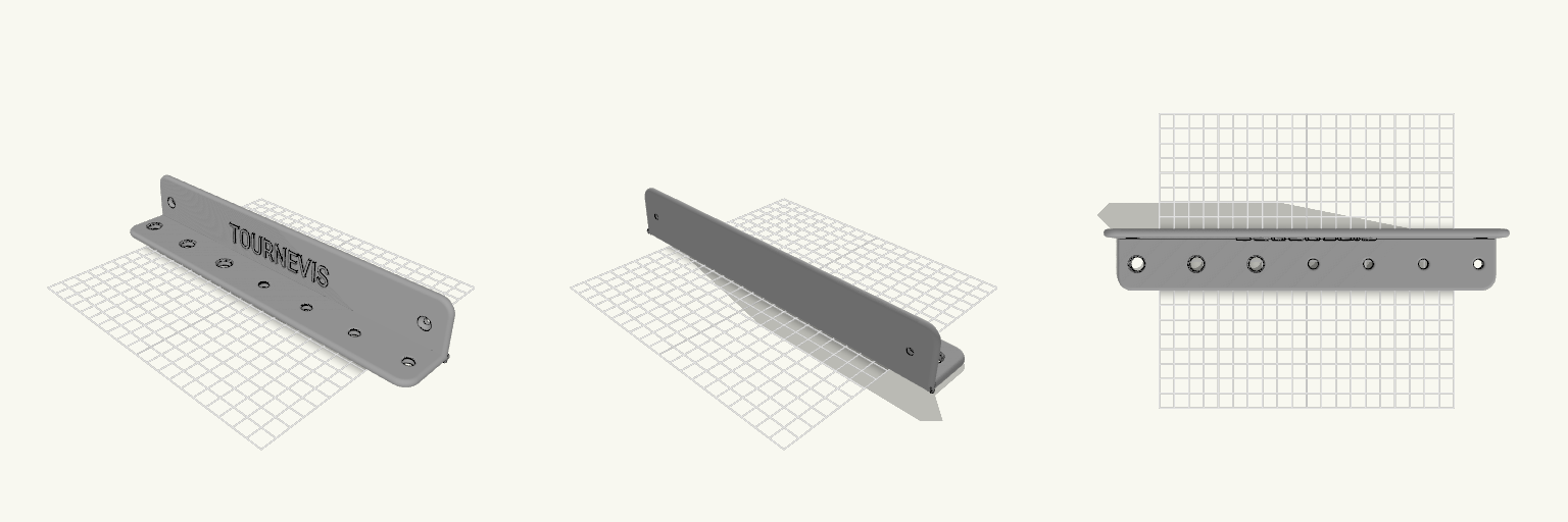
Support mural tournevis 255 × 40 × 40 mm
Support mural pour tournevis : plaque verticale de 255 × 40 mm et tablette horizontale de 255 × 40 mm, épaisseur 5 mm. Trous de la tablette, de gauche à droite : 10, 10, 10, 7, 7, 7, 7 mm, bords arrondis. Deux trous de vis fraisés dans la plaque. Texte « TOURNEVIS » en relief de 1,5 mm. Coins extérieurs arrondis à 10 mm ; les deux coins à la jonction plaque/tablette sont droits. À vérifier avant impression : la longueur de 255 mm doit tenir sur votre plateau. Ne convient pas aux tournevis dont la tige dépasse 10 mm.
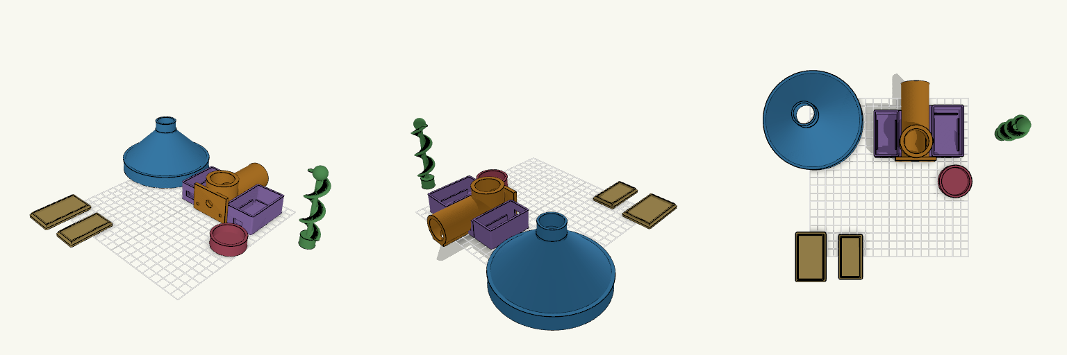
28BYJ-48 Solid One-Piece Kibble Auger
Solid one-piece helical auger for a 28BYJ-48 geared stepper, running in a 26 mm housing bore, with the funnel and electronics cases printed alongside. Fit Motor: 28BYJ-48 only (5 mm shaft with 3 mm flats). Bore: 26 mm; flight tip 24.4 mm. Kibble: sized for about 11.5 mm pieces. Check before printing Thread pitch on the 109 mm funnel is assumed at 6 mm. Measure the host opening. The auger prints in one piece, so the flight overhangs may need supports. Does not fit Motors with a different shaft profile or hole spacing. Housing bores other than 26 mm.