Dorso per fogli A4 in diagonale
Created 5 days ago
Description
Dorso per tenere uniti i fogli A4: senza nulla che li trattenga, il pacco scivola fuori dal canale. Qui il canale ha nervature interne che mordono i fogli, e le pareti sono cave per risparmiare filamento.
Misure e stampa
- Lunghezza 297 mm, stampato ruotato di 45° (circa 220 mm di ingombro per lato)
- Canale 2,5 mm, nervature da 0,5 mm ogni 10 mm
- Pareti da 2,4 mm con cavità interna chiusa da 0,8 mm
- Altezza 14 mm, fondo da 2 mm
- Larghezza totale 7,3 mm
Images
More like this
Explore more in Desk & Tech →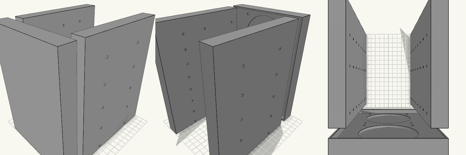
Octobay — 5.25" to 3.5" Drive Cage
Octobay turns a five-bay stack of half-height 5.25" slots into room for eight 3.5" drives, and adds a 25 mm front cage that carries two 92 mm fans. The outer side faces take M3 heat-set inserts, so the whole cage screws into the case's 5.25" rails instead of resting on them. Everything is one printed part: the drive stack, the side mounting blocks and the fan cage print as a single body. Because the fans close off the front, drives now load from the back. The fan cavity behind the grille is hollow, so air still passes through to the drive stack. Dimensions Overall: 145 mm wide × 197.5 mm deep × 205.5 mm tall Fits: five half-height 5.25" bays Holds: eight 3.5" drives, stacked vertically Drive channel: 102.6 mm wide — 1 mm of play around a 101.6 mm drive Mounting 20 insert holes, 10 per side, for M3 heat-set inserts — 4.2 mm across and 6 mm deep Two insert holes per bay, at 41.3 and 117.5 mm from the front, 6.35 mm above each bay floor Solid blocks sit behind each hole to give the inserts something to bite into Three M3 screw holes per side per drive, at 14, 76.6 and 117.6 mm from the front Cross ribs sit clear of the screw holes so a screwdriver can reach every fastener Fan cage Two 92 mm fans, stacked vertically on the 25 mm front section 88 mm fan openings with 4.4 mm screw holes on the standard 82.5 mm square pattern Hollow cavity behind the fans feeds air to the drive channels Print notes Drive channels are open at the back, top and bottom, and the gaps between the inner and outer side walls are open for cable routing. Screw and insert positions and the 205.5 mm height follow common 5.25" bay standards; they have not been checked against a specific case, so measure your bay rails and drives before printing.
Fidget Slider Toy, Captive Print-in-Place
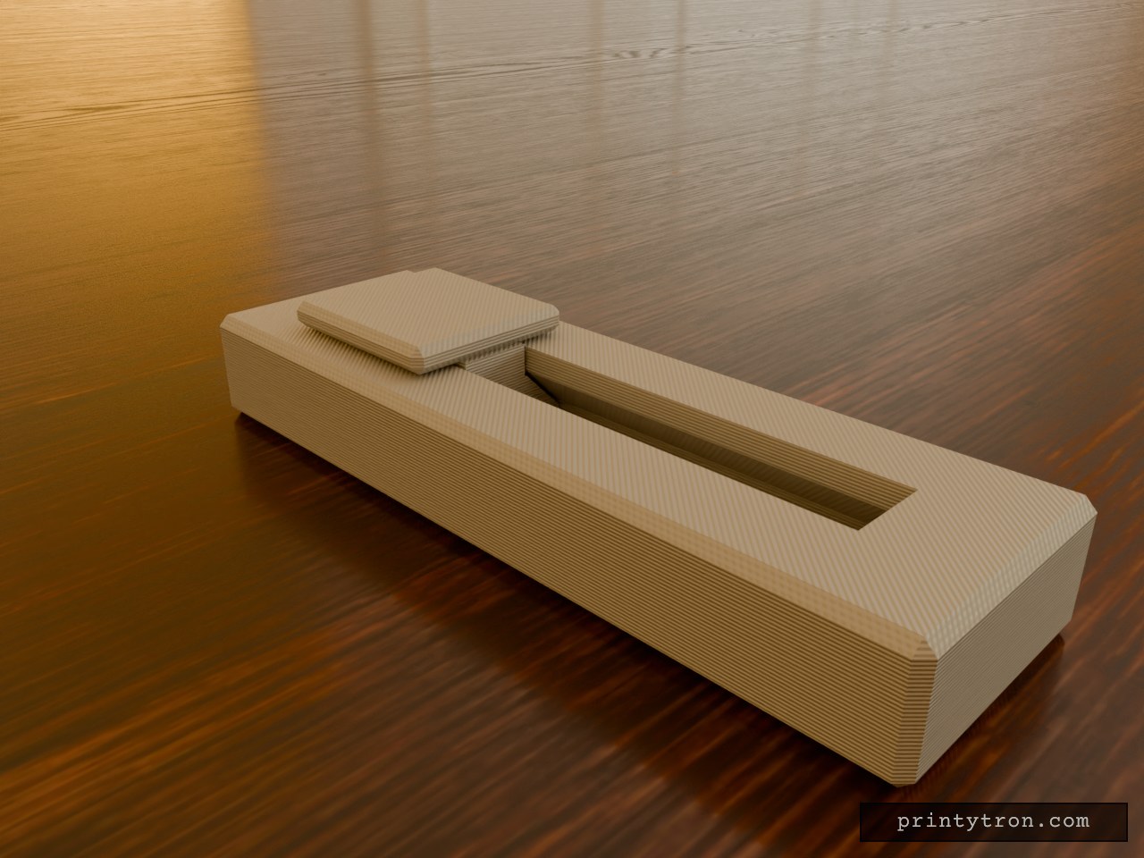
A fidget slider that prints already assembled, so there is no loose weight to lose and nothing to glue. The slider is captured in an enclosed dovetail track and cannot fall out. It runs 40 mm end to end and clicks at each stop instead of rolling freely. What it does Slides back and forth along a closed track in an 80 x 25 mm body. A small bump on the track floor at each end of travel drops into a dimple under the slider and gives the click. The dovetail profile holds the slider down, so it cannot lift out of the rails. Numbers that matter Body: 80 x 25 x 11 mm, with the slider top reaching 14 mm. Slider: 20 mm long, 18 mm wide cap. Travel: 40 mm. Clearance between slider and track: 0.4 mm per side. This is what lets it move after printing. Click bump: about 0.6 mm of interference against the 0.4 mm gap. Reduce the bump height if it feels too stiff. Printing Print flat, body base down, with no supports needed inside the track. Use a well-tuned printer. A 0.4 mm gap fuses easily if the flow is too high. After printing, work the slider back and forth a few times to break any thin bridging between the slider and the rails. Two colours show as separate parts in the preview, but the print is one job.
Virgin-Rot-Weiß: Boeing 777 Standmodell
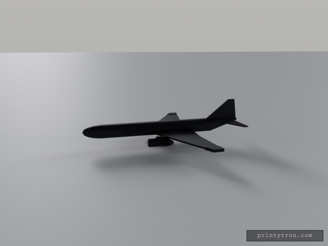
Virgin-Rot auf Weiß: Der weiße Rumpf mit rotem Bauchstreifen, das rote, gepfeilte Seitenleitwerk und die roten Triebwerke an den Flügeln bringen den Virgin-Atlantic-Look auf den Tisch. Die Boeing 777 steht als Standmodell mit gewölbter Nase, hochgezogenem Heck, blauen Fensterreihen und schrägen Cockpitscheiben; auf beiden Rumpfseiten steht „virgin atlantic“ in roter Schrift. Einläufe und Ständer sind weiß gehalten. Was dran ist: Maßstab etwa 1:320 – rund 230 mm lang und 200 mm Spannweite Gepfeilte Flügel mit roten Spitzen, Triebwerke an Pylonen mit weißen Einläufen Fensterreihen und Cockpitfenster in Blau, roter Bauchstreifen und Schriftzug „virgin atlantic“ Kein Fahrwerk – ein weißer Ständer trägt das Modell Farben getrennt wählbar: Weiß für Rumpf, Flügel, Höhenleitwerk, Einläufe und Ständer; Rot für Leitwerk, Triebwerke, Spitzen, Streifen und Schrift; Blau für die Fenster
Bisel frontal para pantalla táctil de 10,1"
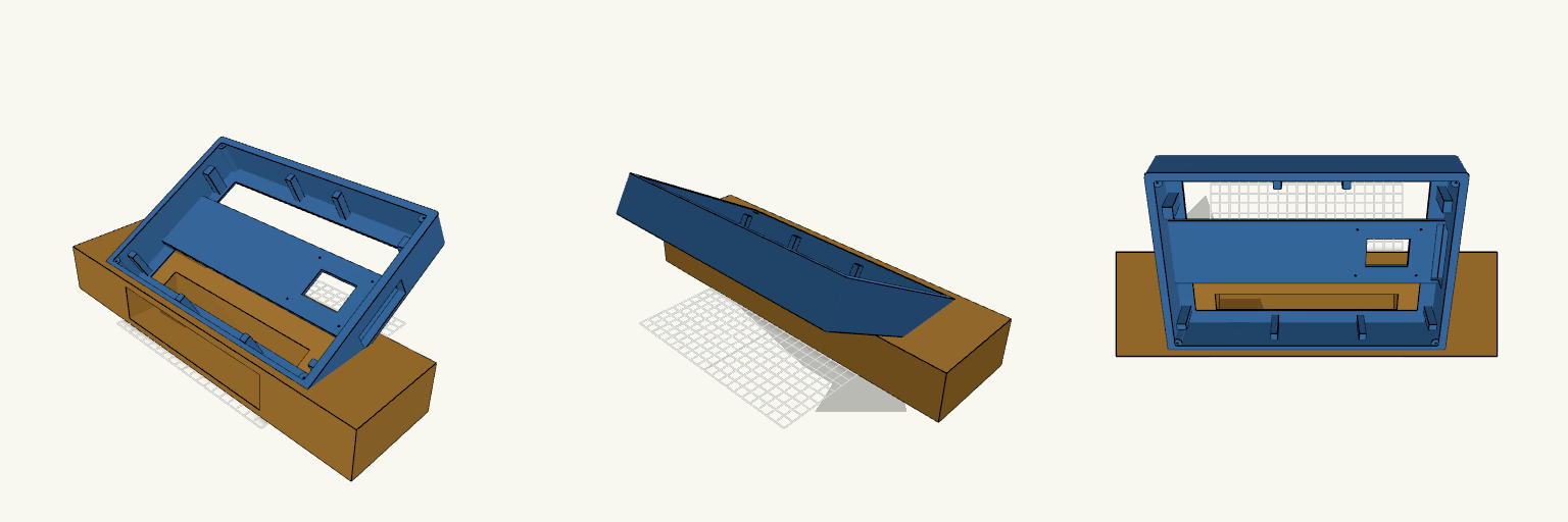
Bisel frontal para una pantalla táctil de 10,1 pulgadas (tipo Raspberry Pi Touch Display 2), en horizontal, inclinado 30° respecto a la horizontal y montado sobre una base de bloque. El bisel tiene sección en L: una placa frontal de 1,6 mm con la ventana de visión y una pared perimetral de 7 mm que baja hacia atrás, con la parte trasera abierta para alojar el panel. La ventana es recta, sin chaflán, y está descentrada respecto al contorno exterior. Detrás de la zona de la pantalla va un soporte para atornillar la Raspberry Pi, bajado 4 mm hacia la placa frontal, de modo que los postes apoyan en la cara interior de la placa; la barra del soporte tiene una abertura de 40 × 30 mm y la pared lateral +X tiene una ranura abierta de 60 × 20 mm para USB y Ethernet. Los cuatro agujeros guía de los postes siguen abiertos. El modelo consta de dos volúmenes, Bisel y Base. El bisel es una pieza entera, sin recortar contra el bloque, y va hundido en la base: su borde inferior queda por debajo de la cara superior del bloque. La base tiene un hueco posterior con la forma exterior del bisel, de modo que la pieza encaja dentro, y conserva la abertura frontal para el paso de los cables. Cotas del bisel Exterior: 265,05 × 183,75 mm, con 40 mm de profundidad total y esquinas exteriores redondeadas (~3,5 mm); borde frontal redondeado (~1,5 mm). Placa frontal: 1,6 mm de grosor; pared perimetral de 7 mm. Ventana de visión: 220,5 × 138,65 mm, recta, sin chaflán y descentrada. Cavidad interior para la pantalla: 251,05 × 169,75 mm. Base e inclinación Bloque de 365 × 100 mm de planta y 50 mm de alto, unos 5 cm más ancho por cada lado que el bisel. Inclinación del bisel: 30° respecto a la horizontal. La base conserva un hueco posterior con la forma del cuerpo del bisel; solo queda maciza alrededor de ese hueco. Abertura para cables de la controladora en la cara frontal de la base: rectángulo de 180 × 37 mm, centrado en horizontal, que arranca a 6 mm de la cara inferior y penetra 9 mm en el bloque. Medidas en la placa de impresión: Bisel 265 × 177,1 × 126 mm; Base 365 × 100 × 50 mm. Comprueba que ambas caben en el volumen de impresión disponible. Verifica en la vista previa que la cara frontal y la ventana quedan despejadas y que el bisel encaja en el hueco de la base sin dejar escalón. Soporte de Raspberry Pi y cables Barra transversal de 3 mm, de pared a pared, situada justo detrás de la zona de la pantalla, con su cara posterior a unos 6,6–9,6 mm de la cara frontal; no llega al borde trasero. Cuatro postes de 5 mm que apoyan en la cara interior de la placa frontal, con agujero guía de 2,2 mm para tornillos M2,5 pasante hasta la placa; separación de 58 × 49 mm. La placa queda desplazada hacia +X, con centro en X=75 mm. La barra del soporte tiene una abertura de 40 × 30 mm centrada en X=75 mm. La ranura lateral para USB y Ethernet está abierta en la pared +X, de 60 × 20 mm, a la altura de la barra, y se desplaza con el soporte. El soporte se dimensionó sin un modelo concreto de Raspberry Pi: comprueba la separación de los postes y la posición de los agujeros guía antes de imprimir. Detalles interiores Cuatro torretas cilíndricas macizas de Ø8,2 mm en las esquinas interiores, con centro a ±123,25 mm en horizontal y ±82,7 mm en vertical respecto al centro del marco. Recorren la pared desde la cara interior de la placa hasta 2 mm antes del borde trasero, y quedan recortadas por el contorno exterior. Agujero pasante en cada torreta, de delante hacia atrás: apertura redonda de Ø5 mm en la cara frontal, cono de 45° que baja de Ø5 a Ø2 en 1,5 mm y tramo de Ø2 mm hasta salir abierto por detrás. Admite tornillos autorroscantes de hasta Ø2 mm. Profundidad del tramo de Ø5 mm, distinta por esquina: 5,75 mm en las dos inferiores, 4,55 mm en una superior y 3,15 mm en la otra. Canto de la pared perimetral nivelado, sin muesca ni rebaje: el borde trasero queda liso y a una sola altura en todo el perímetro. Ocho tacos de apoyo sobre la cara interior de la placa, de reparto asimétrico: dos arriba, dos abajo y dos en cada lateral. Llegan hasta 7 mm del borde trasero, de modo que con la pared de 40 mm son mucho más altos que los 2 mm del diseño de partida; mantienen esa distancia al borde trasero, no la altura. Impresión Dos volúmenes independientes: bisel y base. La pared perimetral de 7 mm se resuelve con perímetros múltiples con boquilla de 0,4 mm. Torretas y tacos llegan casi hasta el borde trasero: al imprimir con la cara frontal sobre la cama son columnas altas, conviene revisar que no vuelquen. Revisa que la barra y los postes del soporte de la Pi no interfieran con el panel y que la separación de 58 × 49 mm coincida con tu placa. La ventana coincide con la zona activa del panel (220,5 × 138,65 mm), por lo que el ajuste es ceñido; verifica las cotas antes de imprimir.
Vertical Switch Dock Stand with Strap Slots
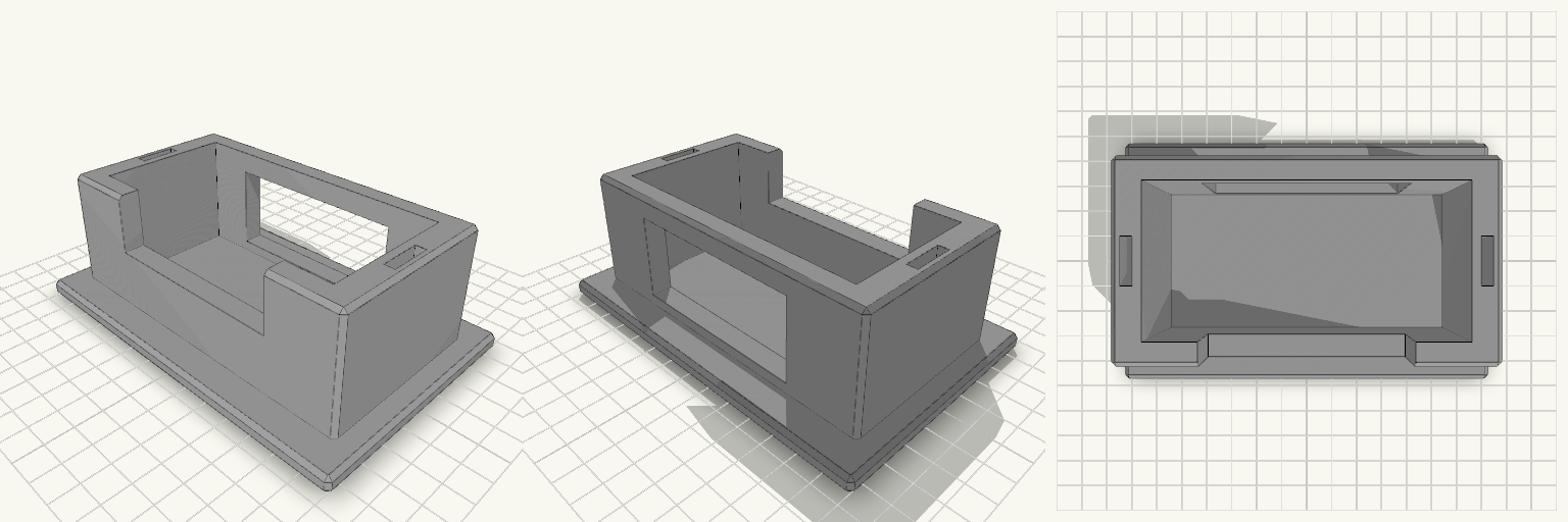
A Switch dock lying flat eats shelf space, and a dock stood on its end tips over the first time someone pulls a cable. This stand holds the dock upright in a snug pocket on a wide flat base, and keeps two spare Joy-Con straps in slots in the side walls. What it does Holds the dock on its end so it takes up a footprint of about 142 × 92 mm instead of its full 175 mm length lying down. Front wall is cut down in the middle, so you can grip the dock to lift it out. A 70 mm opening in the back wall lets the power, HDMI and USB cables leave without bending against the stand. Two 4 × 16 mm slots, one in each side wall, hold spare Joy-Con straps. Numbers that decide fit Pocket: 106 mm wide × 52 mm deep, for a dock of roughly 104 × 49 mm. That leaves about 1 mm of play on width and 3 mm on depth. Pocket depth: 44 mm, above a 6 mm base. Overall: 142 × 92 mm base, 50 mm tall. Side walls: 10 mm thick. Front and back walls: 8 mm. Printing Print flat on the base, with no supports needed. Chamfered edges, 1.5 mm. Any common filament works. PETG or PLA is fine for the load. If your dock is a tight fit or loose, adjust the pocket width and depth to match.
SilentSOS Two-Piece Electronics Enclosure
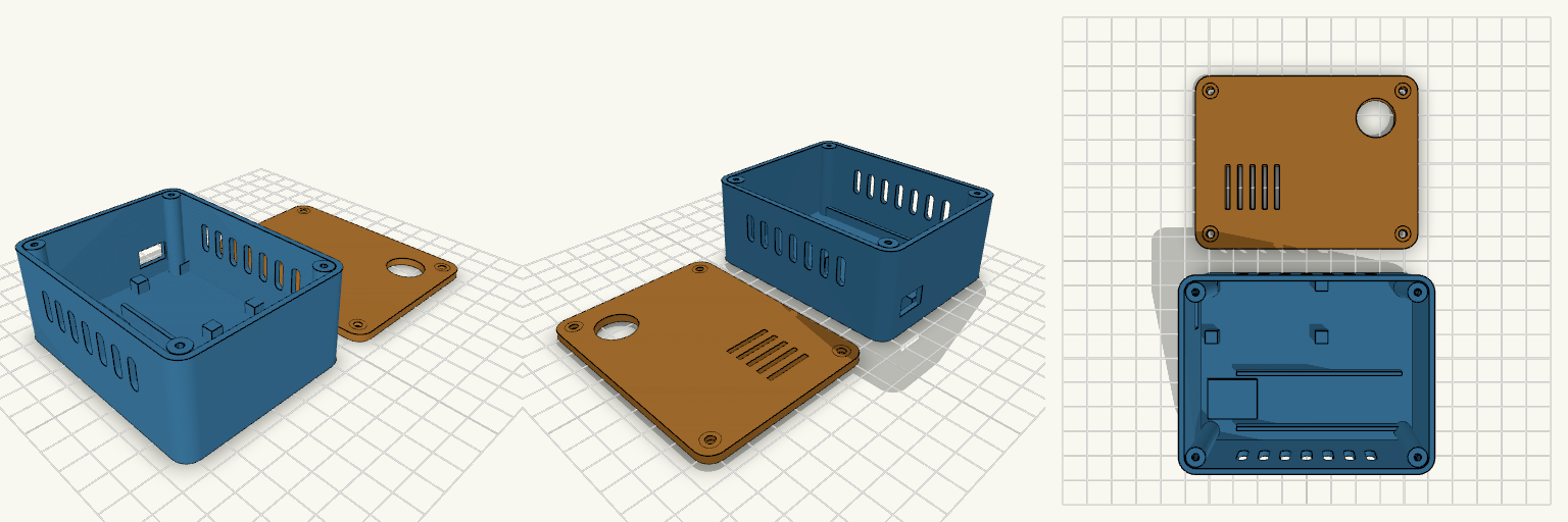
A 90 × 70 × 40 mm two-piece enclosure for an ESP8266 NodeMCU SOS alert device: a 37 mm tall base with 2 mm walls and a separate 3 mm lid, with 6 mm rounded vertical corners. The lid is printed flat and fastens with four M3 screws into corner bosses. Remix hooks Component mounting: no hole positions were guessed. The NodeMCU sits on four 5 mm locating pads at the board corners (49 × 26 mm area, nb, nbc). Once measured, add real standoffs in extraposts as [x, y] pairs and set post_pilot. Battery bay: two 1.5 mm rails 22 mm apart hold a cell of about 18 mm diameter, 65 mm long. Move or space them for other cells. DC-DC zone: a low 20 × 16 mm pad, free to move or resize. USB opening: 13 × 8 mm in the short wall, aligned to the NodeMCU position. SOS button: 16 mm hole in the lid (btnd, btnpos). Ventilation: seven slots in each long wall plus five slots in the lid. Screws: 2.6 mm pilots in the bosses, 3.4 mm countersunk lid holes. Pairs well with heat-set inserts in the bosses, or a gasket strip for a dust-resistant fit. Export base and lid as separate STLs by rendering each module alone.