3D-printable desk & tech accessories
Phone stands, cable management, name plates, camera and tripod mounts — print-ready with real dimensions. Browse what makers built, or describe the exact fit you need and Printy makes it.
Need one that fits your exact measurements? Start building →
Newest
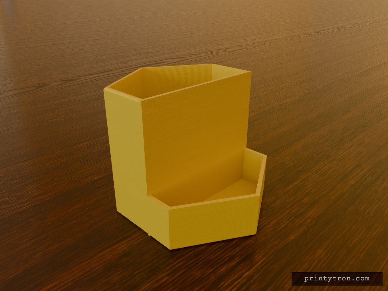
Hexagonal Pen Cup with Divider
A hexagonal desk cup, 80 mm tall and 100 mm point to point, split into two sections by an internal divider wall. The larger section runs full height and holds pens and pencils. The smaller section is cut down to one third of that height, about 27 mm, and works as a tray for paper clips, erasers and other small items. The divider sits slightly off-centre so the short tray takes up roughly 40% of the floor area. The walls are 2.4 mm thick and the base is 3 mm thick. The top and bottom outer edges have a small chamfer. Overall size: 100 mm across corners, 80 mm tall Tall pen section: full height, about 60% of the floor Short tray section: one third height, about 40% of the floor Wall thickness: 2.4 mm, floor thickness: 3 mm Prints upright as one piece with no supports needed
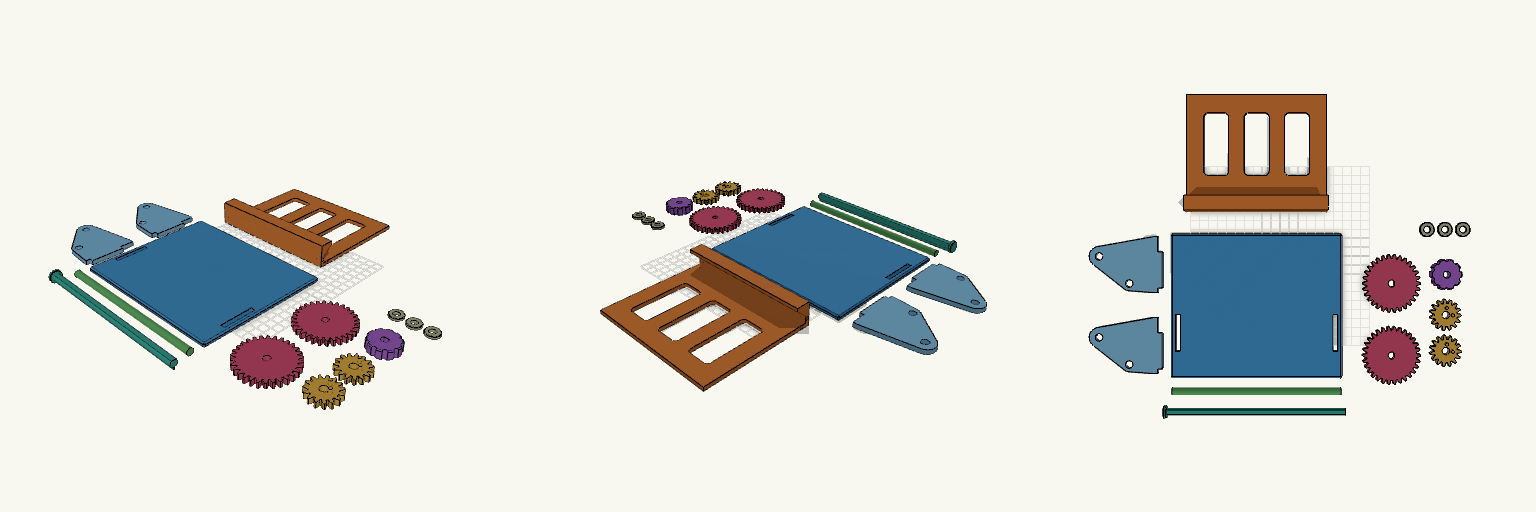
Slot-Together Geared Tablet Stand, Doogee U11
Geared tilting tablet stand for the Doogee U11, laid out as 14 separate flat pieces for printing and assembled by hand after printing. A knob on a drive shaft turns two 30-tooth gears that mesh with 15-tooth gears on the cradle, so a small knob twist tilts the cradle forward or back. Pieces Base plate: 1 Side plates: 2, with tabs that drop into slots in the base Tablet cradle: 1 15-tooth cradle gears: 2, peg into the cradle ends 30-tooth drive gears: 2, keyed to the drive shaft Knob: 1 Axle: 1, 8 mm round Drive shaft: 1, D-profile Friction-fit caps: 3 Print notes Every piece is laid flat on the build plate with no overlap. Gear pegs face up and the shaft flat faces down, so no supports are needed for the main bodies. Clearances are about 0.2-0.4 mm; adjust for your printer. Gear mesh and fit are untested; friction alone holds the tilt angle.
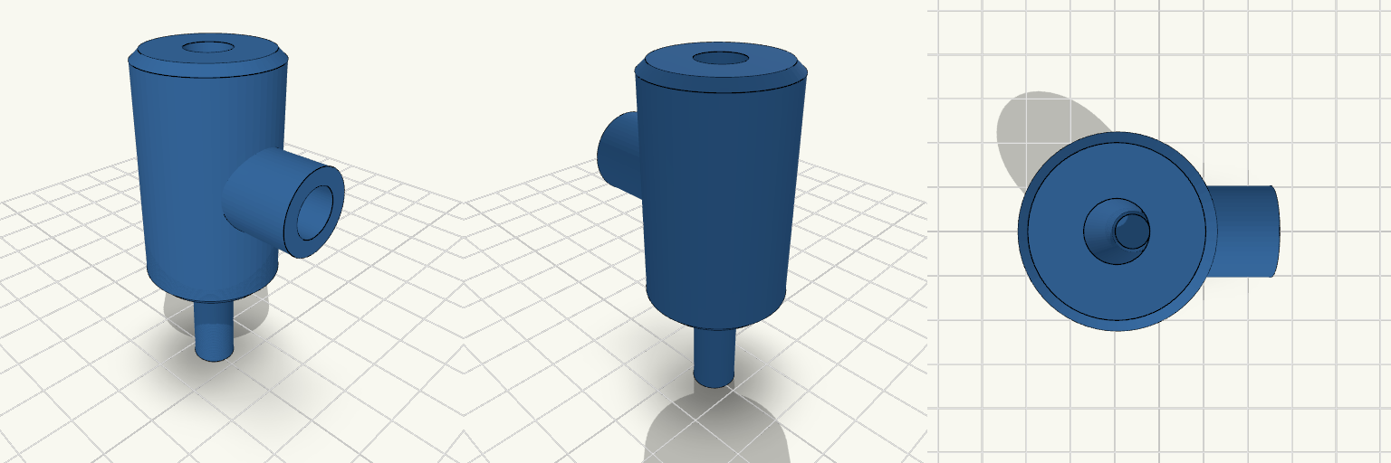
Lichtschirmhalter mit M6-Einschraubmutter und CHB1-Zapfen
Dieser Lichtschirmhalter fixiert einen Lichtschirm mit 7,5-mm-Rundschaft. Die Hülse hat 24 mm Außendurchmesser und 40 mm Höhe; ihre 7,8-mm-Bohrung lässt dem Schaft 0,3 mm Spiel. Seitlich sitzt ein Dom mit einer 8,4-mm-Aufnahme, 8 mm tief, für eine M6x8-Einschraubmutter. Eine 6,4-mm-Bohrung führt zur Schaftbohrung, sodass die M6-Schraube direkt auf den Schirm drückt. Unter der Hülse sitzt ein 7,7-mm-Zapfen, 20 mm lang, für das 8-mm-Loch am Neewer CHB1; auch hier 0,3 mm Spiel, die Kante ist angefast. Auf der Druckplatte misst der Aufbau 34 × 24 × 60 mm. Ansatzpunkte zum Weiterbauen Schaftbohrung: 7,8 mm für einen 7,5-mm-Schaft. Bei einem anderen Schirm ist das der erste Wert, der angepasst werden muss; 0,2–0,3 mm Spiel reichen aus. CHB1-Zapfen: 7,7 mm Durchmesser und 20 mm Länge für ein 8-mm-Loch. Für eine andere Halterung lassen sich Durchmesser und Länge ändern, ohne die Hülse selbst anzutasten. Mutteraufnahme: 8,4 mm Durchmesser und 8 mm Tiefe für eine M6x8-Einschraubmutter. Der Außendurchmesser streut je nach Hersteller – hier lohnt sich ein Nachmessen vor dem Druck. Mantel: 24 mm Außendurchmesser und 40 mm Höhe bestimmen Wandstärke, Domfleisch und Führungslänge. Kürzer trägt flacher auf, länger stabilisiert stärker. Paarung: Gedacht für Lichtschirme an Studioblitzen mit Bowens-Anschluss und Neewer CHB1; der Zapfen lässt sich als Aufnahme unter der Hülse weiterentwickeln.
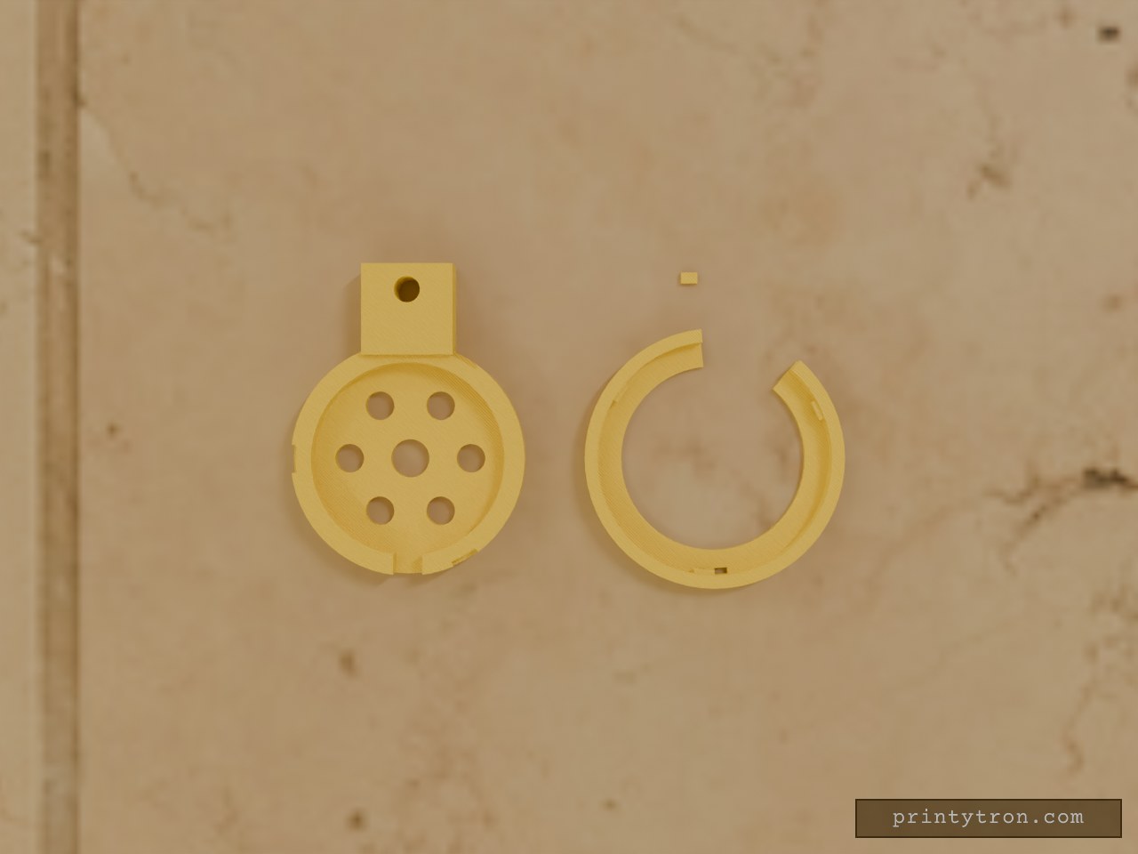
W-MA11SV用 バヨネット式 充電器ホルダー 3部品
ELECOM W-MA11SV Qi2 25W充電器を浅い受け皿に入れ、別体の保持リングで外周の丸い膨らみだけを押さえる充電器ホルダーです。充電面プレートと外周の平坦部は覆わず、リング前端は充電器前面より約0.8 mm奥に収まります。ホルダー本体、保持リング、ロックキーの3部品を別々に印刷して組み立てます。 仕様 構成:ホルダー本体、バヨネット式保持リング、逆回転防止用ロックキー 印刷配置寸法:ホルダー本体 72 × 96 × 10 mm、保持リング 80.8 × 80.6 × 5.7 mm、ロックキー 5.1 × 3.4 × 1.4 mm 受け内径:59.6 mm リング開口径:57.8 mm(充電面プレートと平坦部を覆わない寸法) 保持方式:3突起のバヨネット。35°回転でロックし、ロックキーで逆回転を止める ケーブル逃げ:6時方向に幅9 mmの切り欠き。リング側も回転全行程でケーブルを避ける 放熱:底面に通風孔6個と中央穴を配置 材料想定:PLA。シリコン、Oリング、金属部品、接着剤を使わない構成 アーム接続:歯付き関節との接続は未統合。本体の+Y側に仮の接続タブと径8 mmの穴がある 実機での嵌合、保持力、リングの回しやすさ、ロックキーの抜き差しは未確認です。
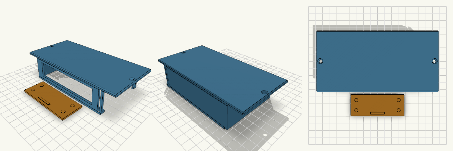
Under Desk Switch Mount With Cover
A Flex Mini 2.5G that sits loose in an under-desk bracket slides out the open end the first time someone bumps a cable. This mount screws to the desk underside and closes that end with a slide-in cover. Pocket: 110 × 72 × 28.5 mm, 5 mm bottom lips, wide port window in the front wall, cable slot in the -X end. Cover: 2.8 mm plate slides up into a 3.2 mm slot at the +X end. Four small bumps hold it by friction. Mounting: two countersunk screw ears on the top plate. Print: mount with the top plate face down; cover flat as laid out. No supports needed for the cover. Check the pocket size against your unit before printing.
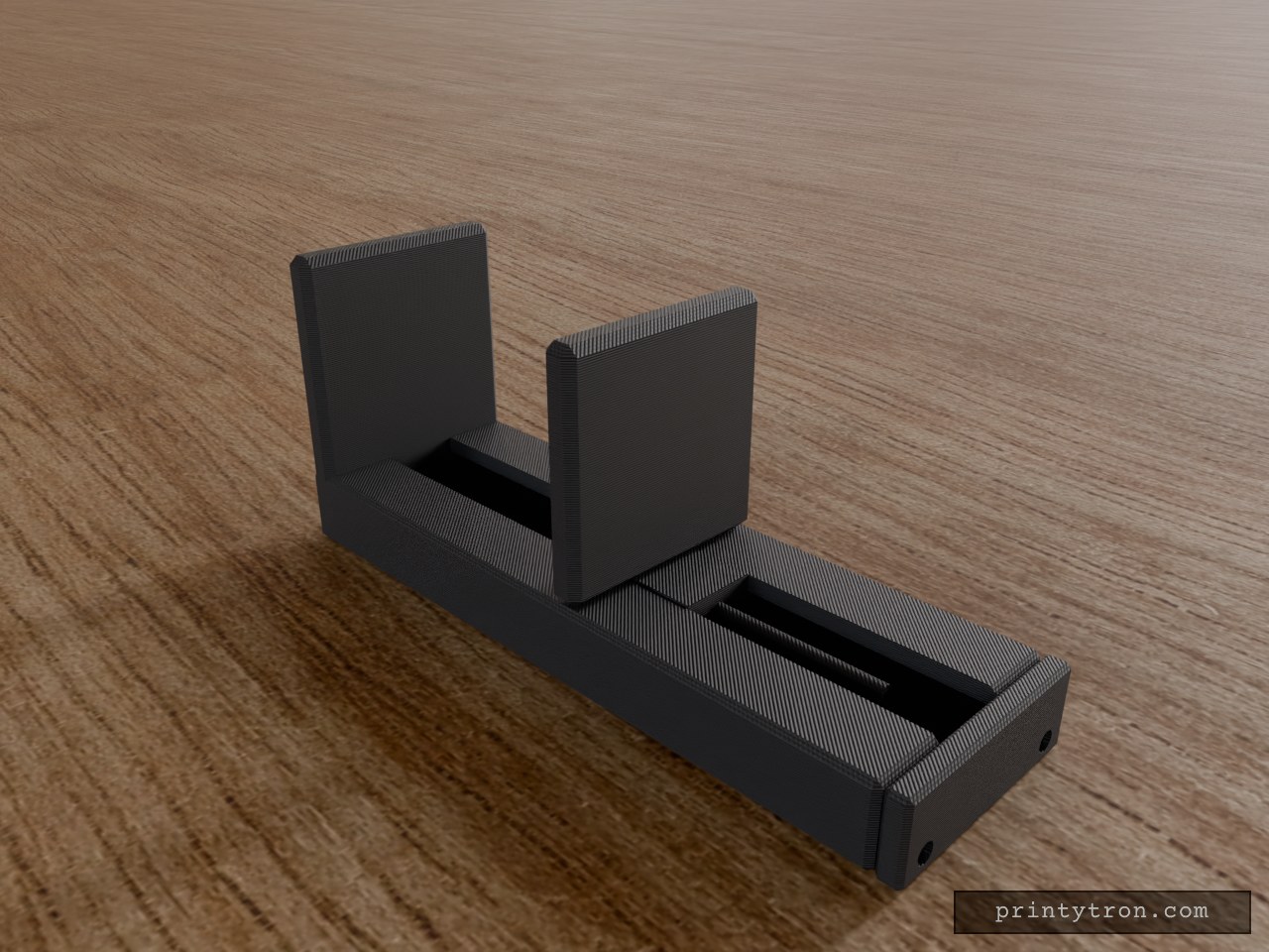
1/4-20 Tripod Spring Phone Clamp, 60–85mm
This is a spring-loaded phone clamp for a standard 1/4-20 tripod mount. It has a fixed jaw, a sliding jaw and a screw-on end cap. The base has a hex pocket that holds a 7/16 in across-flats 1/4-20 nut, with a 6.8 mm bore above it for the tripod screw. What it fits Phones 60–85 mm wide, measured across the body including any case, in portrait orientation. Tripod heads with a 1/4-20 UNC male stud. This is the common camera and phone tripod standard. Jaw faces are chamfered on the inner edges so they don't mar the phone. Check before printing Measure your nut across the flats. The pocket is sized for a 7/16 in (11.1 mm) hex 1/4-20 nut. A nut with a different flat size will rattle or won't seat. Hardware you supply 1 × 1/4-20 hex nut, 7/16 in across flats. 1 × compression spring, about 6 mm OD and 45 mm free length, over the slider's 3 mm guide rod. 2 × M3 screws for the end cap. The pilot holes are 2.6 mm. Does not fit Phones narrower than 60 mm or wider than 85 mm. Metric tripod studs such as 3/8 in or M6. The bore is sized only for 1/4-20. Landscape use on very heavy phones. Spring force is untested, and it is lowest near the 85 mm end. A heavy phone in a thick case may be loose there. Parts Base and fixed jaw Sliding jaw End cap
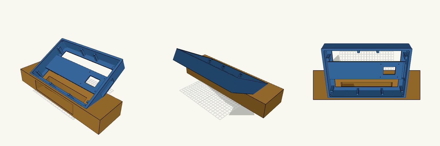
Bisel frontal para pantalla táctil de 10,1"
Bisel frontal para una pantalla táctil de 10,1 pulgadas (tipo Raspberry Pi Touch Display 2), en horizontal, inclinado 30° respecto a la horizontal y montado sobre una base de bloque. El bisel tiene sección en L: una placa frontal de 1,6 mm con la ventana de visión y una pared perimetral de 7 mm que baja hacia atrás, con la parte trasera abierta para alojar el panel. La ventana es recta, sin chaflán, y está descentrada respecto al contorno exterior. Detrás de la zona de la pantalla va un soporte para atornillar la Raspberry Pi, bajado 4 mm hacia la placa frontal, de modo que los postes apoyan en la cara interior de la placa; la barra del soporte tiene una abertura de 40 × 30 mm y la pared lateral +X tiene una ranura abierta de 60 × 20 mm para USB y Ethernet. Los cuatro agujeros guía de los postes siguen abiertos. El modelo consta de dos volúmenes, Bisel y Base. El bisel es una pieza entera, sin recortar contra el bloque, y va hundido en la base: su borde inferior queda por debajo de la cara superior del bloque. La base tiene un hueco posterior con la forma exterior del bisel, de modo que la pieza encaja dentro, y conserva la abertura frontal para el paso de los cables. Cotas del bisel Exterior: 265,05 × 183,75 mm, con 40 mm de profundidad total y esquinas exteriores redondeadas (~3,5 mm); borde frontal redondeado (~1,5 mm). Placa frontal: 1,6 mm de grosor; pared perimetral de 7 mm. Ventana de visión: 220,5 × 138,65 mm, recta, sin chaflán y descentrada. Cavidad interior para la pantalla: 251,05 × 169,75 mm. Base e inclinación Bloque de 365 × 100 mm de planta y 50 mm de alto, unos 5 cm más ancho por cada lado que el bisel. Inclinación del bisel: 30° respecto a la horizontal. La base conserva un hueco posterior con la forma del cuerpo del bisel; solo queda maciza alrededor de ese hueco. Abertura para cables de la controladora en la cara frontal de la base: rectángulo de 180 × 37 mm, centrado en horizontal, que arranca a 6 mm de la cara inferior y penetra 9 mm en el bloque. Medidas en la placa de impresión: Bisel 265 × 177,1 × 126 mm; Base 365 × 100 × 50 mm. Comprueba que ambas caben en el volumen de impresión disponible. Verifica en la vista previa que la cara frontal y la ventana quedan despejadas y que el bisel encaja en el hueco de la base sin dejar escalón. Soporte de Raspberry Pi y cables Barra transversal de 3 mm, de pared a pared, situada justo detrás de la zona de la pantalla, con su cara posterior a unos 6,6–9,6 mm de la cara frontal; no llega al borde trasero. Cuatro postes de 5 mm que apoyan en la cara interior de la placa frontal, con agujero guía de 2,2 mm para tornillos M2,5 pasante hasta la placa; separación de 58 × 49 mm. La placa queda desplazada hacia +X, con centro en X=75 mm. La barra del soporte tiene una abertura de 40 × 30 mm centrada en X=75 mm. La ranura lateral para USB y Ethernet está abierta en la pared +X, de 60 × 20 mm, a la altura de la barra, y se desplaza con el soporte. El soporte se dimensionó sin un modelo concreto de Raspberry Pi: comprueba la separación de los postes y la posición de los agujeros guía antes de imprimir. Detalles interiores Cuatro torretas cilíndricas macizas de Ø8,2 mm en las esquinas interiores, con centro a ±123,25 mm en horizontal y ±82,7 mm en vertical respecto al centro del marco. Recorren la pared desde la cara interior de la placa hasta 2 mm antes del borde trasero, y quedan recortadas por el contorno exterior. Agujero pasante en cada torreta, de delante hacia atrás: apertura redonda de Ø5 mm en la cara frontal, cono de 45° que baja de Ø5 a Ø2 en 1,5 mm y tramo de Ø2 mm hasta salir abierto por detrás. Admite tornillos autorroscantes de hasta Ø2 mm. Profundidad del tramo de Ø5 mm, distinta por esquina: 5,75 mm en las dos inferiores, 4,55 mm en una superior y 3,15 mm en la otra. Canto de la pared perimetral nivelado, sin muesca ni rebaje: el borde trasero queda liso y a una sola altura en todo el perímetro. Ocho tacos de apoyo sobre la cara interior de la placa, de reparto asimétrico: dos arriba, dos abajo y dos en cada lateral. Llegan hasta 7 mm del borde trasero, de modo que con la pared de 40 mm son mucho más altos que los 2 mm del diseño de partida; mantienen esa distancia al borde trasero, no la altura. Impresión Dos volúmenes independientes: bisel y base. La pared perimetral de 7 mm se resuelve con perímetros múltiples con boquilla de 0,4 mm. Torretas y tacos llegan casi hasta el borde trasero: al imprimir con la cara frontal sobre la cama son columnas altas, conviene revisar que no vuelquen. Revisa que la barra y los postes del soporte de la Pi no interfieran con el panel y que la separación de 58 × 49 mm coincida con tu placa. La ventana coincide con la zona activa del panel (220,5 × 138,65 mm), por lo que el ajuste es ceñido; verifica las cotas antes de imprimir.
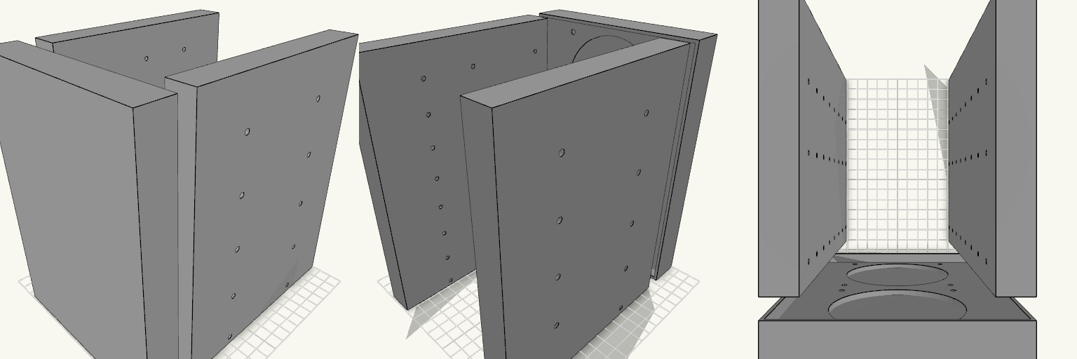
Octobay — 5.25" to 3.5" Drive Cage
Octobay turns a five-bay stack of half-height 5.25" slots into room for eight 3.5" drives, and adds a 25 mm front cage that carries two 92 mm fans. The outer side faces take M3 heat-set inserts, so the whole cage screws into the case's 5.25" rails instead of resting on them. Everything is one printed part: the drive stack, the side mounting blocks and the fan cage print as a single body. Because the fans close off the front, drives now load from the back. The fan cavity behind the grille is hollow, so air still passes through to the drive stack. Dimensions Overall: 145 mm wide × 197.5 mm deep × 205.5 mm tall Fits: five half-height 5.25" bays Holds: eight 3.5" drives, stacked vertically Drive channel: 102.6 mm wide — 1 mm of play around a 101.6 mm drive Mounting 20 insert holes, 10 per side, for M3 heat-set inserts — 4.2 mm across and 6 mm deep Two insert holes per bay, at 41.3 and 117.5 mm from the front, 6.35 mm above each bay floor Solid blocks sit behind each hole to give the inserts something to bite into Three M3 screw holes per side per drive, at 14, 76.6 and 117.6 mm from the front Cross ribs sit clear of the screw holes so a screwdriver can reach every fastener Fan cage Two 92 mm fans, stacked vertically on the 25 mm front section 88 mm fan openings with 4.4 mm screw holes on the standard 82.5 mm square pattern Hollow cavity behind the fans feeds air to the drive channels Print notes Drive channels are open at the back, top and bottom, and the gaps between the inner and outer side walls are open for cable routing. Screw and insert positions and the 205.5 mm height follow common 5.25" bay standards; they have not been checked against a specific case, so measure your bay rails and drives before printing.
Vertical Switch Dock Stand with Strap Slots
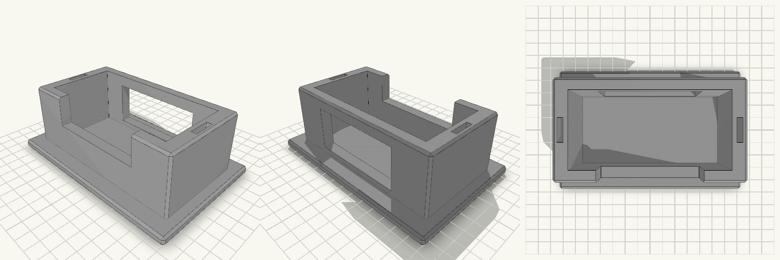
A Switch dock lying flat eats shelf space, and a dock stood on its end tips over the first time someone pulls a cable. This stand holds the dock upright in a snug pocket on a wide flat base, and keeps two spare Joy-Con straps in slots in the side walls. What it does Holds the dock on its end so it takes up a footprint of about 142 × 92 mm instead of its full 175 mm length lying down. Front wall is cut down in the middle, so you can grip the dock to lift it out. A 70 mm opening in the back wall lets the power, HDMI and USB cables leave without bending against the stand. Two 4 × 16 mm slots, one in each side wall, hold spare Joy-Con straps. Numbers that decide fit Pocket: 106 mm wide × 52 mm deep, for a dock of roughly 104 × 49 mm. That leaves about 1 mm of play on width and 3 mm on depth. Pocket depth: 44 mm, above a 6 mm base. Overall: 142 × 92 mm base, 50 mm tall. Side walls: 10 mm thick. Front and back walls: 8 mm. Printing Print flat on the base, with no supports needed. Chamfered edges, 1.5 mm. Any common filament works. PETG or PLA is fine for the load. If your dock is a tight fit or loose, adjust the pocket width and depth to match.
SilentSOS Two-Piece Electronics Enclosure
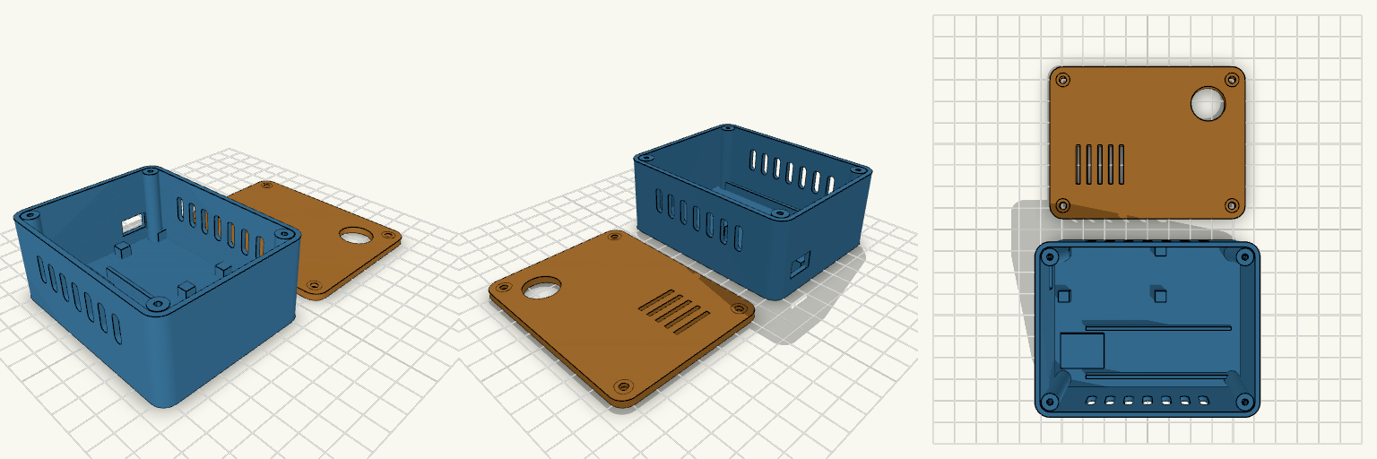
A 90 × 70 × 40 mm two-piece enclosure for an ESP8266 NodeMCU SOS alert device: a 37 mm tall base with 2 mm walls and a separate 3 mm lid, with 6 mm rounded vertical corners. The lid is printed flat and fastens with four M3 screws into corner bosses. Remix hooks Component mounting: no hole positions were guessed. The NodeMCU sits on four 5 mm locating pads at the board corners (49 × 26 mm area, nb, nbc). Once measured, add real standoffs in extraposts as [x, y] pairs and set post_pilot. Battery bay: two 1.5 mm rails 22 mm apart hold a cell of about 18 mm diameter, 65 mm long. Move or space them for other cells. DC-DC zone: a low 20 × 16 mm pad, free to move or resize. USB opening: 13 × 8 mm in the short wall, aligned to the NodeMCU position. SOS button: 16 mm hole in the lid (btnd, btnpos). Ventilation: seven slots in each long wall plus five slots in the lid. Screws: 2.6 mm pilots in the bosses, 3.4 mm countersunk lid holes. Pairs well with heat-set inserts in the bosses, or a gasket strip for a dust-resistant fit. Export base and lid as separate STLs by rendering each module alone.
Crossfader Knob 20x8x10 mm
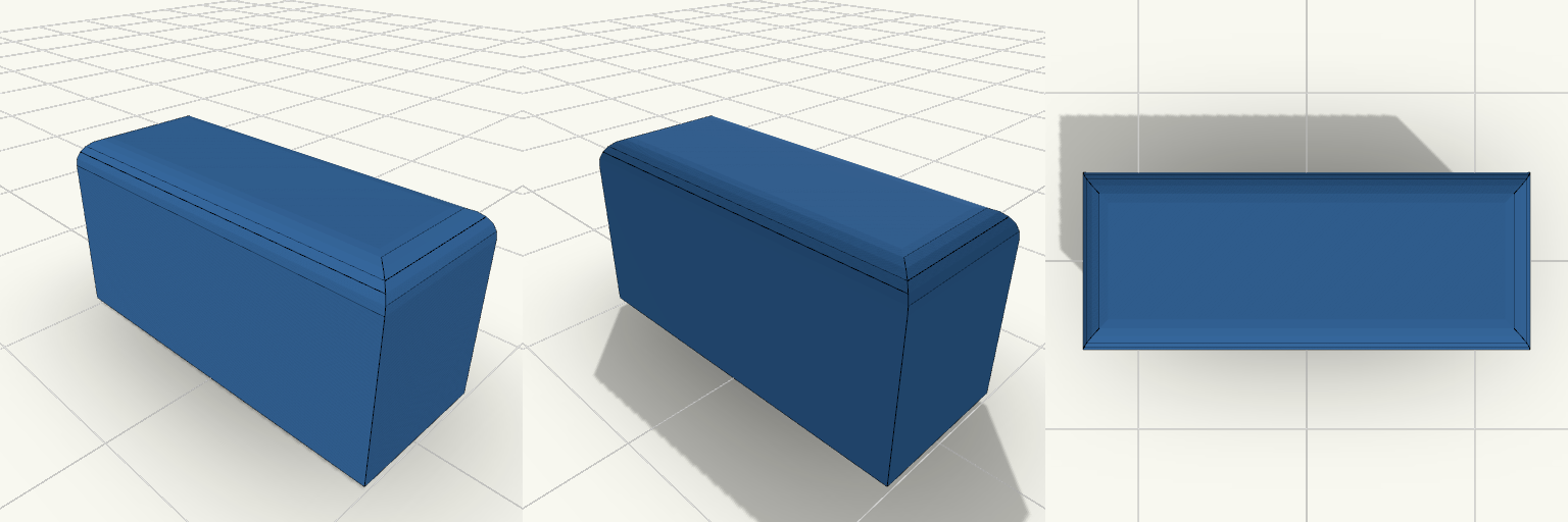
What it's for A solid rectangular crossfader knob for a DJ controller, with a centred socket underneath that fits over the fader stem. The socket's long side now runs across the knob width (Y). Dimensions Knob: 20 × 8 × 10 mm, top edges rounded 1.5 mm. Socket: 1.5 × 4.0 mm stem plus 0.1 mm clearance per side, 6 mm deep, with a small lead-in chamfer. The stem size is a placeholder; adjust stemw and stemt to match the real fader. Remix ideas Swap the socket for a D-shaped or round stem. Add grip ridges on the top face. Increase the height for a taller handle.
Arecson — Base con Pilares de Pulsador
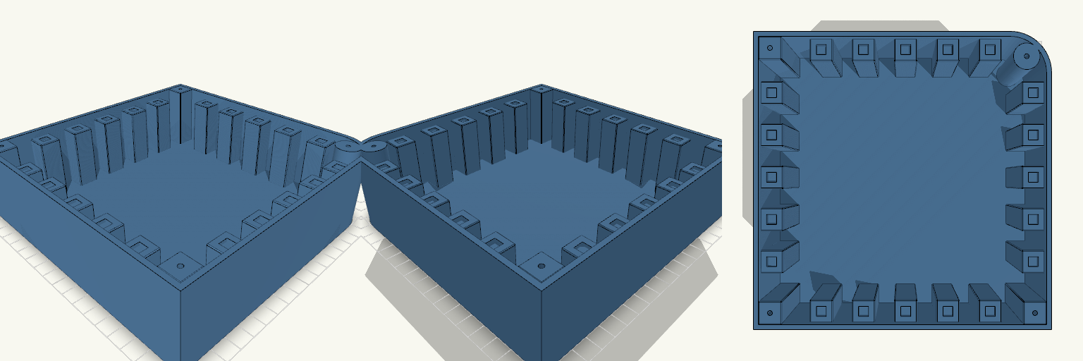
Arecson es una base de caja de 180 × 180 × 50 mm con una sola esquina redondeada, pensada para un controlador DJ. Cuatro pilares de esquina, uno de ellos cilíndrico en la curva, permiten atornillar la tapa, y una fila de cinco pilares sostiene pulsadores de 6 mm. Características Caja de una pieza, sin tapa, con suelo plano. Pilares de esquina de 50 mm con guía de 3 mm y 30 mm de profundidad. Cinco pilares de 14 × 14 × 45 mm en fila horizontal en la zona inferior. Asiento de 6,1 mm y 2 mm de profundidad en cada pilar. Notas de impresión Si el pulsador entra justo, subir el asiento a 6,2 mm.
Tapa 180x180 con 3 crossfaders y 7 potenciómetros
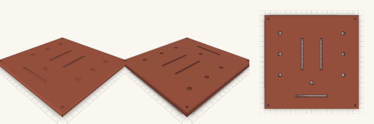
Tapa de 180 × 180 × 5 mm para un controlador DJ, con tres ranuras de crossfader y siete agujeros de potenciómetro de 7 mm. Medidas a comprobar Ranuras de crossfader: 60 × 4 mm (el largo total del recorte según la ficha de tu modelo). Agujeros de potenciómetro: 7 mm, seis a ±60 mm en X y uno central en X = 0, Y = −40 mm. Cuatro tornillos M3 avellanados en las esquinas. No incluye Taladros de fijación de los crossfaders ni de los potenciómetros.
Bedside Reading Glasses Stand, 18mm Bridge
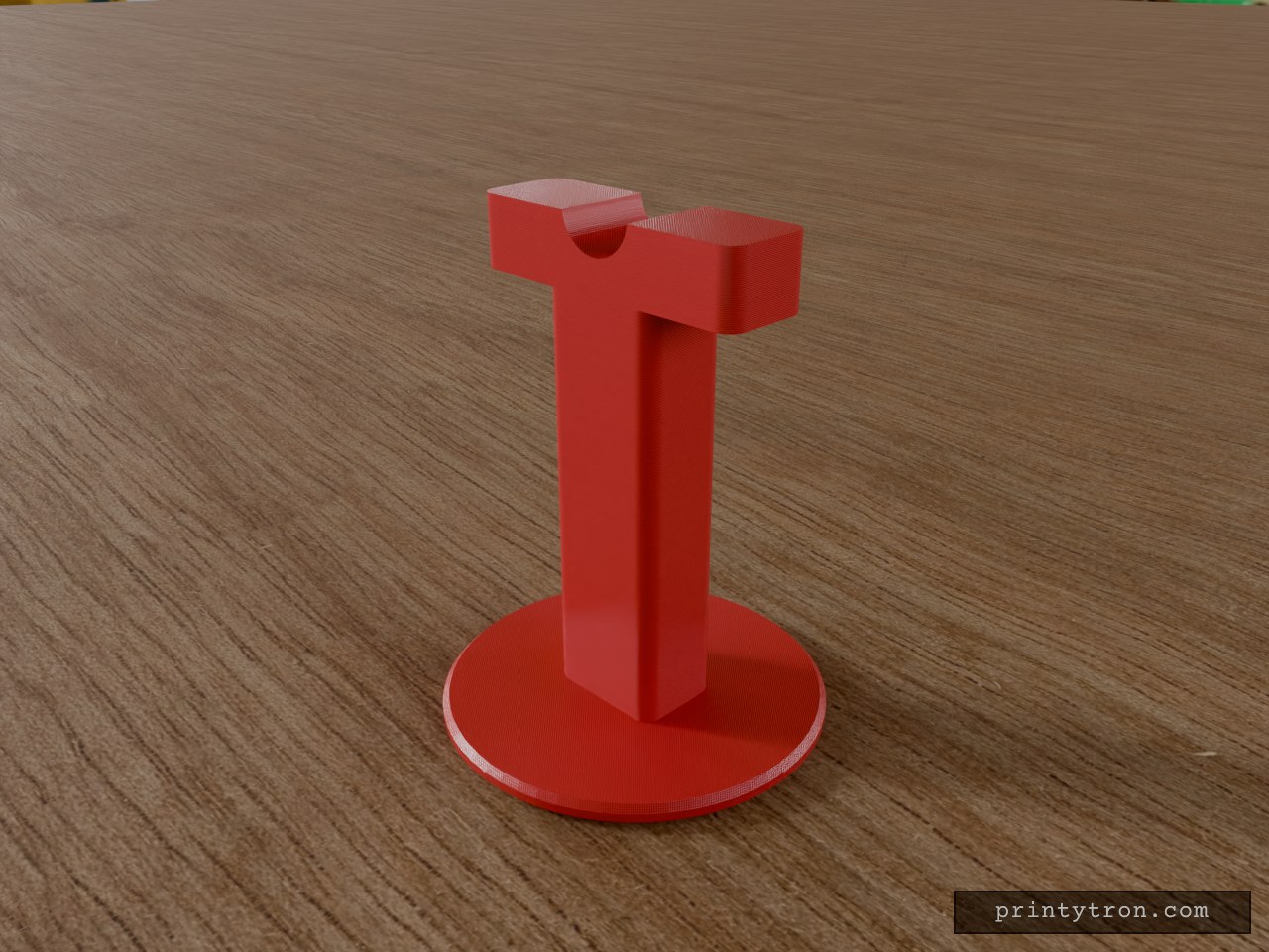
A freestanding bedside stand that holds a pair of reading glasses by the bridge, so they rest off the nightstand and out of the bedding. The top of the column is shaped into a rounded nose-bridge saddle, 18 mm wide at the rim, matching the typical lens-to-lens distance on standard reading glasses. A 90 mm round base keeps the stand upright. Specs Overall size: 90 mm diameter x 116 mm tall Base: 90 mm diameter, 5 mm thick, chamfered edge Column: 30 x 22 mm cross-section, rounded vertical corners Top block: 70 x 22 mm, 16 mm tall Saddle: round dip, 18 mm wide at the rim, 8 mm deep Single-piece body, prints base-down with no supports needed Suggested material: PLA or PETG; 3 or more perimeters for a stiff column Use Place on a nightstand and hang the glasses by the bridge across the saddle. The wide top block and 90 mm base keep the stand stable under light glasses.
Neewer Mini to Bowens Adapter
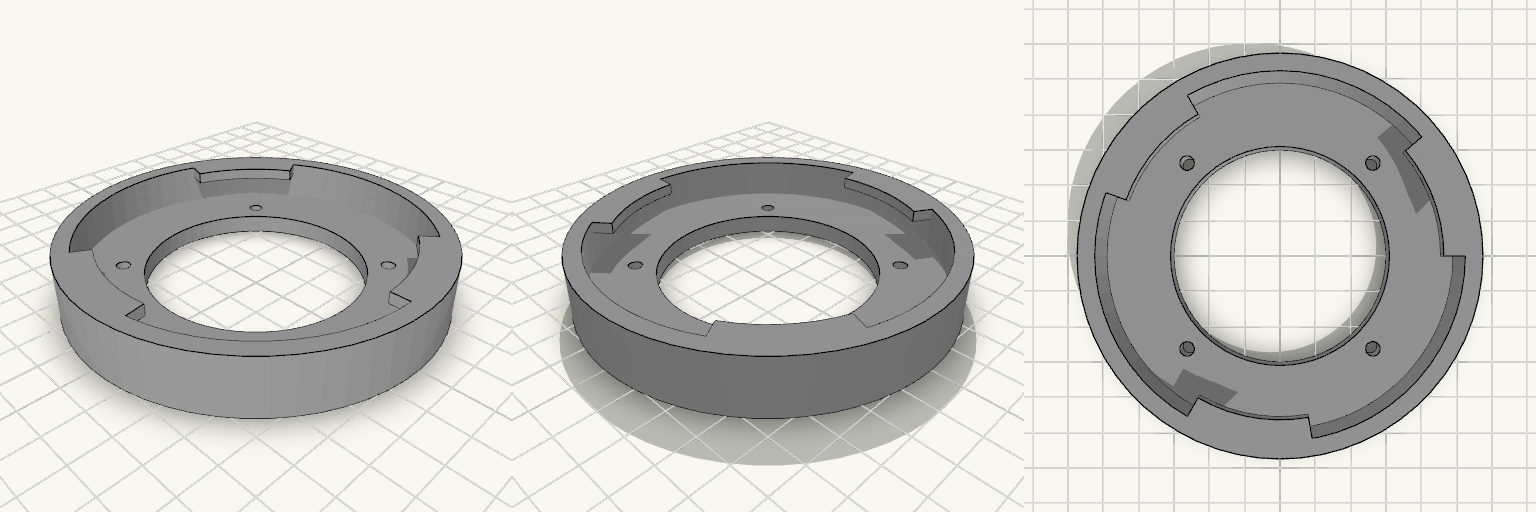
LumenLock is a round bayonet adapter that takes a Neewer mini mount and presents a female Bowens-style socket. A 104 mm body carries a 95 mm pocket, and three inward tabs grip the male lugs of a Bowens-headed light: the lugs pass through the gaps between the tabs, then lock when you twist. The 60 mm centre opening and the four 4 mm mounting holes at 45° spacing pass straight through, and the whole part sits 16 mm tall, so it adds little depth between the light and the modifier. Dimensions Body: 104 × 104 mm Overall height: 16 mm Socket pocket: 95 mm, cut 5 mm above the base Tab opening: 84 mm across Centre opening: 60 mm Mounting holes: four at 4 mm, 45° spacing Tabs: three, each spanning 40° of arc Fit notes The socket and tab sizes are estimated rather than measured from hardware. Check your mini mount's bolt spacing and test the tab arc and the pocket depth against your Bowens male fitting before committing to a long print; real mounts vary, so adjust the hole positions or tab geometry to suit your hardware.
Fidget Slider Toy, Captive Print-in-Place
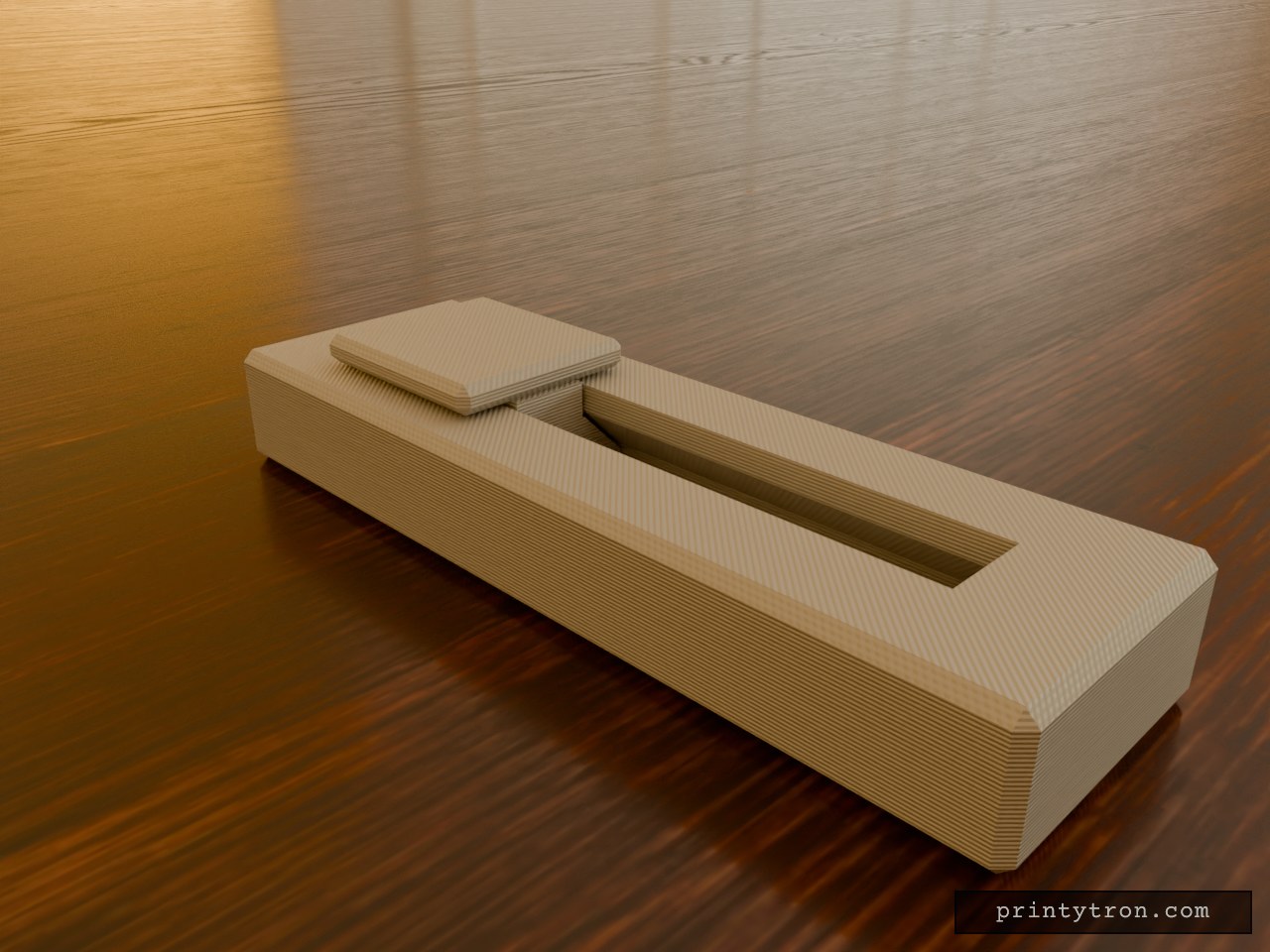
A fidget slider that prints already assembled, so there is no loose weight to lose and nothing to glue. The slider is captured in an enclosed dovetail track and cannot fall out. It runs 40 mm end to end and clicks at each stop instead of rolling freely. What it does Slides back and forth along a closed track in an 80 x 25 mm body. A small bump on the track floor at each end of travel drops into a dimple under the slider and gives the click. The dovetail profile holds the slider down, so it cannot lift out of the rails. Numbers that matter Body: 80 x 25 x 11 mm, with the slider top reaching 14 mm. Slider: 20 mm long, 18 mm wide cap. Travel: 40 mm. Clearance between slider and track: 0.4 mm per side. This is what lets it move after printing. Click bump: about 0.6 mm of interference against the 0.4 mm gap. Reduce the bump height if it feels too stiff. Printing Print flat, body base down, with no supports needed inside the track. Use a well-tuned printer. A 0.4 mm gap fuses easily if the flow is too high. After printing, work the slider back and forth a few times to break any thin bridging between the slider and the rails. Two colours show as separate parts in the preview, but the print is one job.
Bearing-Driven Tri-Lobe Fidget Spinner
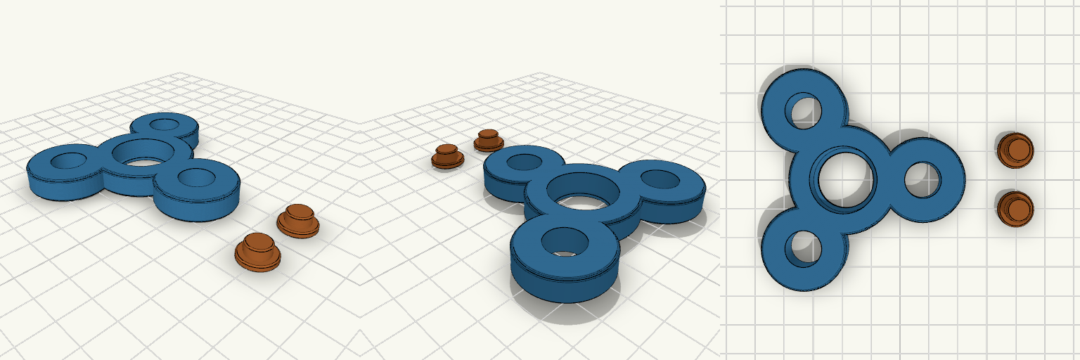
A classic three-lobe hand spinner, the shape every desk drawer has seen, rebuilt around a real 608 skate bearing so it spins freely for a long time. The body has a bearing pocket in the centre, a lip underneath to hold it, and weight-saving holes in each lobe. Two small caps press into the bearing's inner ring from either side to make the finger pads. Notes You need: one 608 bearing (8 × 22 × 7 mm). Print: body flat; the two caps print flat-side down beside it. No supports. Assembly: press the bearing into the pocket from the top, then push one cap in from each side until they meet. Tuning: if the bearing is loose or tight in the pocket, adjust the pocket diameter slightly. Remix: the lobe holes can be enlarged to take 608 bearings as extra weights.
Lockdown — Dev Board Case With Camera Eye
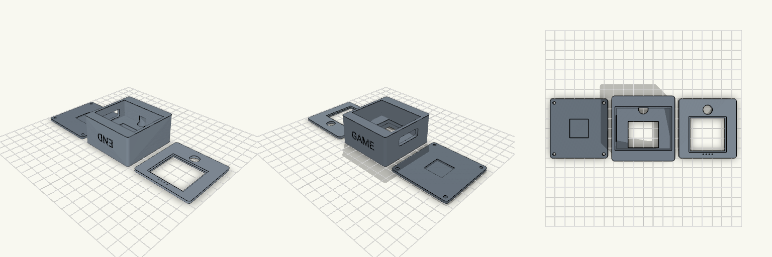
Lockdown is a three-part enclosure for a Freenove ESP32-S3 WROOM CAM board with a 35.5 × 33.5 mm display. The front bezel turns the screen into a face, with a 9.6 mm camera eye above the window. The side wall carries one wide cable opening, so USB-C plugs and cables pass straight through the housing. Features 58 × 60 mm footprint across chassis, back cover and bezel Screen pocket with a support ledge and a flex-cable opening 9.6 mm camera bore lined up with the bezel eye Single 26 × 9 mm cable pass-through on the +X wall, raised for a high-mounted board Four M3 screws from the back Embossed-in END and GAME text on the end walls Print notes Print the three parts flat on their backs. PETG works well.
Modular Voice Assistant Enclosure with Rotating Desk Dock
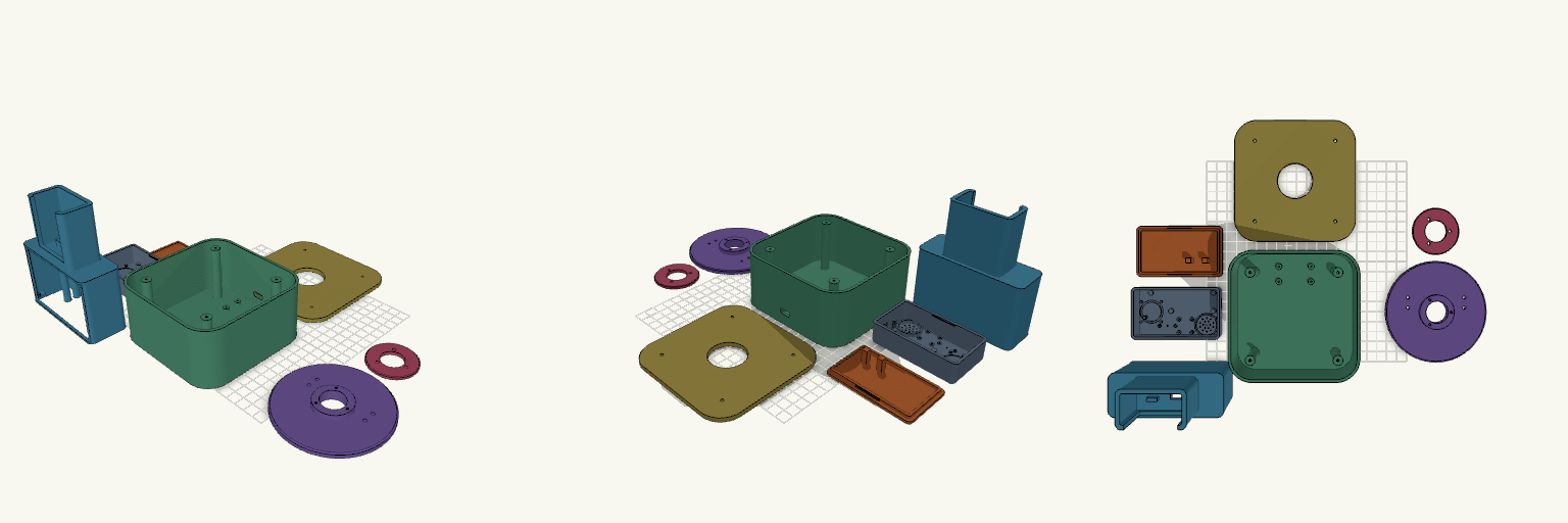
A two-part enclosure system for a modular AI voice assistant: a pocket-sized "Brain" that works on its own, and a desktop station that docks it, swivels a full 360° and carries a 3.5-inch touchscreen behind a removable bezel. Both halves share the same matte-black design language — rounded corners, smooth surfaces and 2–2.5 mm walls — and print as eight separate pieces. What it's for Brain — houses an ESP32-S3 N16R8 board, an INMP441 I2S microphone, a MAX98357A amplifier and a 20 mm speaker behind a grille. A circular LED ring glows through a 0.8 mm front skin for listening, thinking and speaking states; there is no display of its own. A USB-C port sits on the short end, and the unit runs standalone once lifted off the dock. Desk station — a weighted base with a bolted lid carries a swivel plate and the dock tower. The Brain drops into the tower pocket from above with its face still visible, and a USB-C plug cradle in the pocket floor lines up with the port. Display — the tower front takes a standard 98 × 56 mm touchscreen module in landscape, held on four M2 bosses and framed by a bezel that drops into a recess in the front face. Removing four screws frees the display for replacement, and a flat-cable slot below the opening routes the ribbon into the cavity. Rotation — the swivel plate's hollow stem passes through the lid, a retaining ring screws on underneath, and the cable runs down the centre of the stem, so the tower turns 360° without twisting the lead. Dimensions Brain: 85 × 50 × 25 mm overall, with a snap-fit rear cover. Desk base: 120 × 120 mm with 22 mm corner radii; base, lid and swivel plate stack to 65 mm. Dock tower: 104 × 40 × 119 mm, docking the Brain vertically above the display section. It overhangs the 100 mm swivel plate slightly at the front and rear corners. Display opening: 84 × 54 mm, with mounting bosses behind the wall at ±46 × ±25 mm and M2 pilot holes; bezel 100 × 60 × 2.5 mm. Walls: 2–2.5 mm throughout hollow cavities. Print notes Print the Brain shell face-down for a smooth front skin; the LED ring, microphone port and speaker grille all sit in that face. The rear cover snaps on with two bump-and-groove pairs along the long sides; pads on its inside hold the ESP32 down. The tower's internal floor and the display window bridge wide spans, so expect a little support in the dock tower only. Everything else is oriented to print without it. Print the bezel flat; it is a thin frame and needs no supports. PLA or PETG both work; four rubber-foot recesses under the base are worth filling. All eight pieces — Brain shell, rear cover, desk base, base lid, swivel plate, retaining ring, dock tower and display bezel — are separate. The lid bolts on at four corners and the display bezel screws in from the front. Compatibility The display bosses use M2 pilot holes; check your module's hole spacing before driving screws, since pinouts vary between boards. The dock pocket is sized for the Brain as drawn — if you change the Brain's shell, adjust the pocket in step. Remix ideas Lean the dock back a few degrees for a more natural viewing angle if you can accept the extra support. Swap the removable bezel for a blank panel or a vent if your build has no screen. Scale the docking pocket to fit a different companion device while keeping the same swivel mechanism.
Supporto voltmetro piatto foro 29 mm
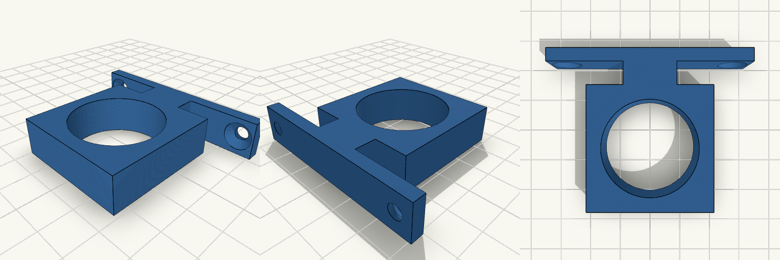
Supporto per voltmetro con foro da 29 mm, da avvitare a una superficie piana, pensato per essere stampato sdraiato: niente ponti sul foro grande e nessun supporto sotto il blocco. Misure e stampa Foro voltmetro: 29,3 mm Spessore del pezzo: 12 mm Base: 62 mm di larghezza, 4 mm di altezza Blocco intorno al foro: 38×38 mm Fori di fissaggio: 2 da 4,5 mm con svasatura a 9 mm, interasse 52 mm Stampa: appoggiato sul lato largo, senza supporti, anche solo 2 perimetri bastano
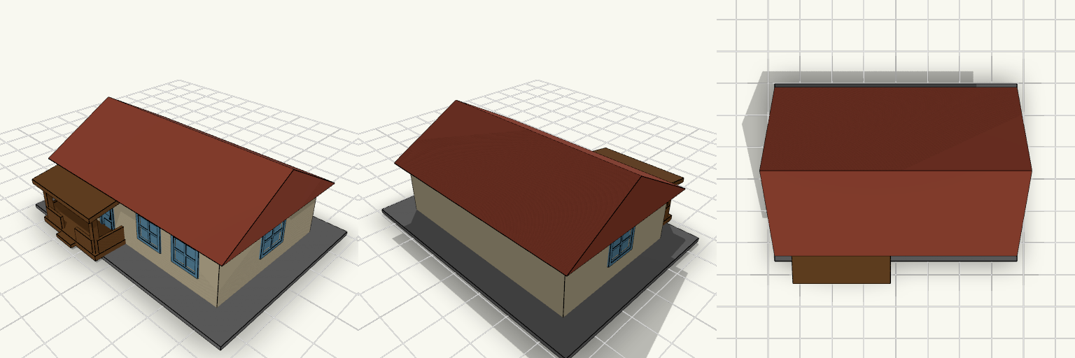
caja parte drcha
Casa en miniatura de una sola pieza con tejado a dos aguas, porche frontal, puerta y ventanas, reducida a la mitad del tamaño H0 original. Medidas de partida Planta de paredes: 60 x 40 mm, altura de paredes 16 mm Altura total con tejado: 30 mm Base: 75 x 55 mm, 1 mm de grosor Paredes: 1 mm de grosor Ideas para remezclar Escala: todo cuelga de un único factor de escala (0,5). Subirlo a 0,75 da un punto intermedio con detalles más robustos. Marcos y cristales: a esta escala los travesaños son muy finos; engrosarlos mejora la impresión. Porche: ancho (25 mm), postes y barandillas se pueden cambiar sin tocar la casa. Combina con: vallas, árboles y aceras a la misma escala para un diorama.
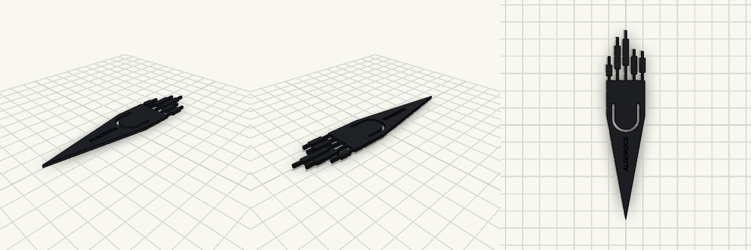
Candlestick Crown Blade Pocket Bookmark
A tapered graphite blade crowned by five candlesticks whose uneven heights still read as a single mountain, with a clear central peak and a natural descent to each side. It sits in the same family as a market-chart skyline, turned into a slim physical object. The lower taper holds an internal page pocket with a flexible inner layer. The page edge enters from the opening near the top of the taper, and the crown stays above the book. Five candles with wicks, two of them hollow ALGOROCK as a fine 0.3 mm raised purple wordmark along the blade Prints flat in one piece, with no supports PETG is recommended for the thin inner layer
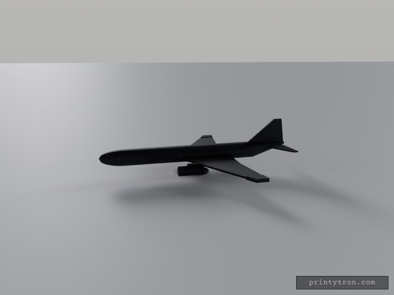
Virgin-Rot-Weiß: Boeing 777 Standmodell
Virgin-Rot auf Weiß: Der weiße Rumpf mit rotem Bauchstreifen, das rote, gepfeilte Seitenleitwerk und die roten Triebwerke an den Flügeln bringen den Virgin-Atlantic-Look auf den Tisch. Die Boeing 777 steht als Standmodell mit gewölbter Nase, hochgezogenem Heck, blauen Fensterreihen und schrägen Cockpitscheiben; auf beiden Rumpfseiten steht „virgin atlantic“ in roter Schrift. Einläufe und Ständer sind weiß gehalten. Was dran ist: Maßstab etwa 1:320 – rund 230 mm lang und 200 mm Spannweite Gepfeilte Flügel mit roten Spitzen, Triebwerke an Pylonen mit weißen Einläufen Fensterreihen und Cockpitfenster in Blau, roter Bauchstreifen und Schriftzug „virgin atlantic“ Kein Fahrwerk – ein weißer Ständer trägt das Modell Farben getrennt wählbar: Weiß für Rumpf, Flügel, Höhenleitwerk, Einläufe und Ständer; Rot für Leitwerk, Triebwerke, Spitzen, Streifen und Schrift; Blau für die Fenster
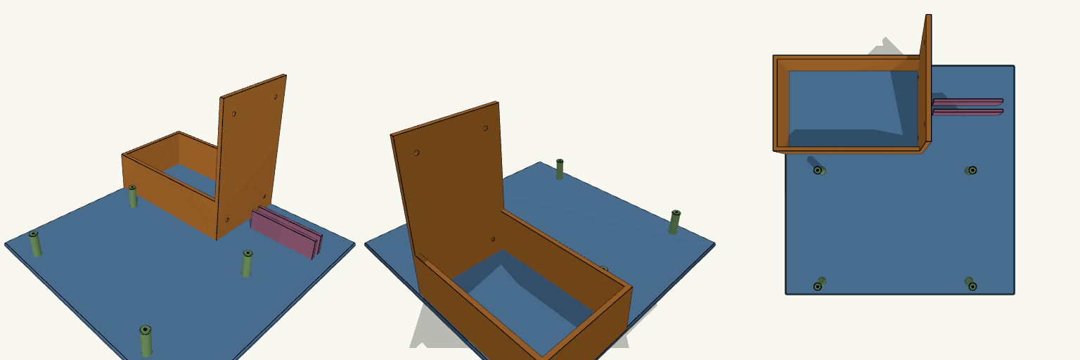
Open-Frame PC Test Bench for 250 mm Beds
An open-frame PC test bench should stop the PSU, motherboard and SSD from shifting while you build; this one does it on a single 250 × 250 mm plate that fits a 256 × 256 mm printer bed. The base is 4 mm thick, and the whole bench prints as one piece in PLA. Fit and print numbers Base plate: 250 × 250 × 4 mm; one-piece print. PSU socket: 140.4 × 86.4 mm pocket with 4 mm walls on three sides; rear bracket 150 mm tall with four ATX screw holes at 64 × 114 mm spacing, 4.2 mm diameter. Motherboard: four 25 mm-high standoffs with 2.8 mm pilot holes for M3, spaced 160 × 120 mm. This is not the standard mATX hole pattern, so check it against your board first; a full mATX board will overhang the plate. SSD: 72 mm-long slot with two 3 mm walls, 22 mm high, holds a 7 mm-thick 2.5-inch drive on its edge. The layout is a compromise for a 250 mm bed: the PSU and board both need room, so the standoff spacing is fixed at 160 × 120 mm rather than a true mATX pattern. Print it in PLA if you want the base stiff without extra parts.
Need a part that doesn't exist yet?
Start building →