Description
A one-piece stand for a 200 × 110 × 18 mm tablet, holding it at 70° from horizontal. Two angled supports are joined by a solid crossbar, with a front lip and a backrest.
Fitment
- Supports are 20 mm wide, centred 100 mm apart, so they land at 50 mm and 150 mm along the tablet's 200 mm width.
- Overall stand width is 120 mm; the tablet overhangs 40 mm each side.
- Slot depth is 20.5 mm for an 18 mm tablet.
- Front lip covers only the bezel.
Check before printing
Measure the tablet's thickness with any case on. Anything over about 20 mm will not enter the slot.
Does not fit
Tablets thicker than 20 mm, or portrait-orientation use, which this stand is not shaped for.
Images
More like this
Explore more in Desk & Tech →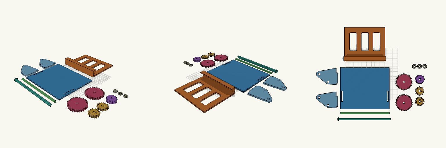
Slot-Together Geared Tablet Stand, Doogee U11
Geared tilting tablet stand for the Doogee U11, laid out as 14 separate flat pieces for printing and assembled by hand after printing. A knob on a drive shaft turns two 30-tooth gears that mesh with 15-tooth gears on the cradle, so a small knob twist tilts the cradle forward or back. Pieces Base plate: 1 Side plates: 2, with tabs that drop into slots in the base Tablet cradle: 1 15-tooth cradle gears: 2, peg into the cradle ends 30-tooth drive gears: 2, keyed to the drive shaft Knob: 1 Axle: 1, 8 mm round Drive shaft: 1, D-profile Friction-fit caps: 3 Print notes Every piece is laid flat on the build plate with no overlap. Gear pegs face up and the shaft flat faces down, so no supports are needed for the main bodies. Clearances are about 0.2-0.4 mm; adjust for your printer. Gear mesh and fit are untested; friction alone holds the tilt angle.
Vertical Switch Dock Stand with Strap Slots
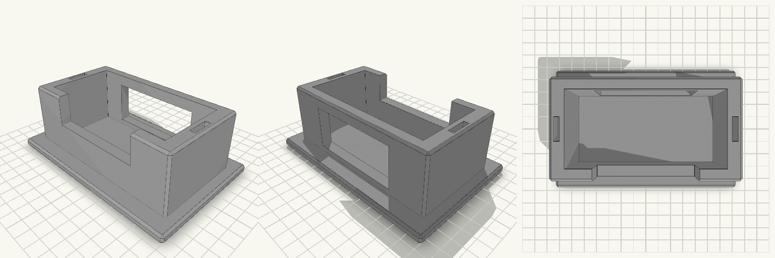
A Switch dock lying flat eats shelf space, and a dock stood on its end tips over the first time someone pulls a cable. This stand holds the dock upright in a snug pocket on a wide flat base, and keeps two spare Joy-Con straps in slots in the side walls. What it does Holds the dock on its end so it takes up a footprint of about 142 × 92 mm instead of its full 175 mm length lying down. Front wall is cut down in the middle, so you can grip the dock to lift it out. A 70 mm opening in the back wall lets the power, HDMI and USB cables leave without bending against the stand. Two 4 × 16 mm slots, one in each side wall, hold spare Joy-Con straps. Numbers that decide fit Pocket: 106 mm wide × 52 mm deep, for a dock of roughly 104 × 49 mm. That leaves about 1 mm of play on width and 3 mm on depth. Pocket depth: 44 mm, above a 6 mm base. Overall: 142 × 92 mm base, 50 mm tall. Side walls: 10 mm thick. Front and back walls: 8 mm. Printing Print flat on the base, with no supports needed. Chamfered edges, 1.5 mm. Any common filament works. PETG or PLA is fine for the load. If your dock is a tight fit or loose, adjust the pocket width and depth to match.
Bedside Reading Glasses Stand, 18mm Bridge
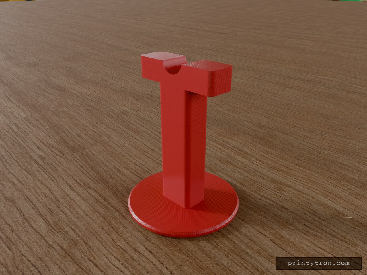
A freestanding bedside stand that holds a pair of reading glasses by the bridge, so they rest off the nightstand and out of the bedding. The top of the column is shaped into a rounded nose-bridge saddle, 18 mm wide at the rim, matching the typical lens-to-lens distance on standard reading glasses. A 90 mm round base keeps the stand upright. Specs Overall size: 90 mm diameter x 116 mm tall Base: 90 mm diameter, 5 mm thick, chamfered edge Column: 30 x 22 mm cross-section, rounded vertical corners Top block: 70 x 22 mm, 16 mm tall Saddle: round dip, 18 mm wide at the rim, 8 mm deep Single-piece body, prints base-down with no supports needed Suggested material: PLA or PETG; 3 or more perimeters for a stiff column Use Place on a nightstand and hang the glasses by the bridge across the saddle. The wide top block and 90 mm base keep the stand stable under light glasses.
Three-Piece Monitor Top Shelf with Rear Legs
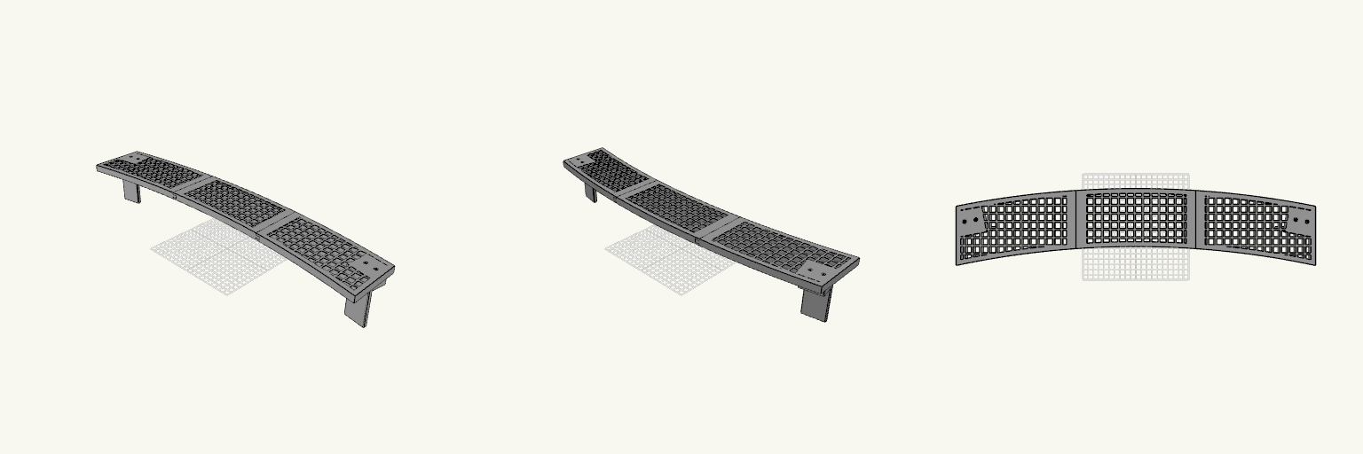
A three-section shelf that sits on the top edge of a 27-inch curved monitor and holds small items above the screen. The shelf follows a 1500R curve, so the ends sit about 32 mm further forward than the centre, and it measures about 620 mm wide by 100 mm deep when the sections are joined. Each section is sized to print on a 250 × 250 mm bed. The shelf surface is a mesh of 11 mm square openings with 3 mm bars on a 14 mm pitch. An 8 mm solid rim runs around the outer edge, and the mesh stops short of the dovetail joints and leaves a solid pad under each leg's screw area. The sections are 12 mm thick. The three sections join with sliding dovetails; slide them together from front to back. The joint has 0.3 mm clearance, giving a light push fit rather than a snap. The two rear legs are separate flat plates. Each leg drops 80 mm behind the monitor, presses against the back of the case, and fastens to the shelf with two M3×20 screws driven down from the top. The screw heads sit in recessed pockets and bite into 2.6 mm pilot holes in the leg tab. Four M3×20 screws are included in the model, two per leg, shown seated in their pockets. Each has a 5.5 × 3 mm head with a hex socket and a 3 × 20 mm shaft. The shafts are plain, with no modelled thread, so they will not cut a real thread in printed plastic — print them lying on their sides, then ream or tap the pilot holes, or substitute metal M3 screws. Small printed screws are fragile, so print a spare. Three shelf sections, each fits a 250 × 250 mm print bed Assembled width about 620 mm; shelf depth about 100 mm 11 mm square mesh openings with 3 mm bars Sliding dovetail joints with 0.3 mm clearance Separate left and right rear legs, 80 mm drop Two M3×20 screws per leg, recessed from the top Four printable M3×20 screws with hex sockets included Print shelf sections flat on the bed; print legs lying on their backs; print screws on their sides Dimensions are set for a 27-inch curved panel and are estimates rather than published monitor figures. The leg plates sit 51 mm behind the screen face, assuming a 40 mm monitor top. Measure your monitor's top edge and the gap to the back bulge before printing, and adjust if they differ.
Octobay — 5.25" to 3.5" Drive Cage
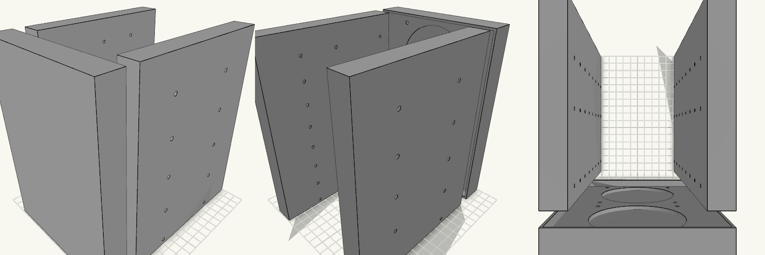
Octobay turns a five-bay stack of half-height 5.25" slots into room for eight 3.5" drives, and adds a 25 mm front cage that carries two 92 mm fans. The outer side faces take M3 heat-set inserts, so the whole cage screws into the case's 5.25" rails instead of resting on them. Everything is one printed part: the drive stack, the side mounting blocks and the fan cage print as a single body. Because the fans close off the front, drives now load from the back. The fan cavity behind the grille is hollow, so air still passes through to the drive stack. Dimensions Overall: 145 mm wide × 197.5 mm deep × 205.5 mm tall Fits: five half-height 5.25" bays Holds: eight 3.5" drives, stacked vertically Drive channel: 102.6 mm wide — 1 mm of play around a 101.6 mm drive Mounting 20 insert holes, 10 per side, for M3 heat-set inserts — 4.2 mm across and 6 mm deep Two insert holes per bay, at 41.3 and 117.5 mm from the front, 6.35 mm above each bay floor Solid blocks sit behind each hole to give the inserts something to bite into Three M3 screw holes per side per drive, at 14, 76.6 and 117.6 mm from the front Cross ribs sit clear of the screw holes so a screwdriver can reach every fastener Fan cage Two 92 mm fans, stacked vertically on the 25 mm front section 88 mm fan openings with 4.4 mm screw holes on the standard 82.5 mm square pattern Hollow cavity behind the fans feeds air to the drive channels Print notes Drive channels are open at the back, top and bottom, and the gaps between the inner and outer side walls are open for cable routing. Screw and insert positions and the 205.5 mm height follow common 5.25" bay standards; they have not been checked against a specific case, so measure your bay rails and drives before printing.
Fidget Slider Toy, Captive Print-in-Place
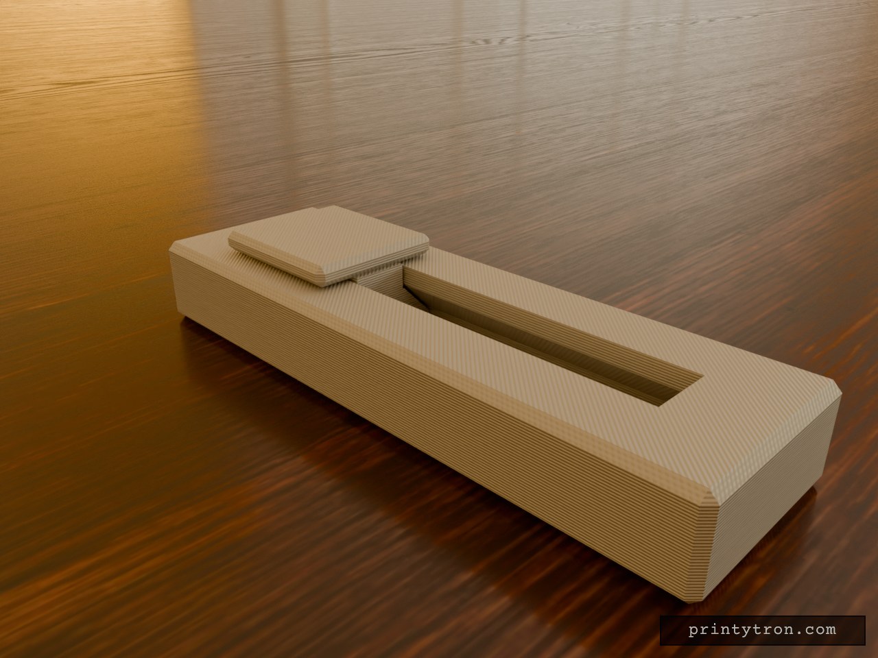
A fidget slider that prints already assembled, so there is no loose weight to lose and nothing to glue. The slider is captured in an enclosed dovetail track and cannot fall out. It runs 40 mm end to end and clicks at each stop instead of rolling freely. What it does Slides back and forth along a closed track in an 80 x 25 mm body. A small bump on the track floor at each end of travel drops into a dimple under the slider and gives the click. The dovetail profile holds the slider down, so it cannot lift out of the rails. Numbers that matter Body: 80 x 25 x 11 mm, with the slider top reaching 14 mm. Slider: 20 mm long, 18 mm wide cap. Travel: 40 mm. Clearance between slider and track: 0.4 mm per side. This is what lets it move after printing. Click bump: about 0.6 mm of interference against the 0.4 mm gap. Reduce the bump height if it feels too stiff. Printing Print flat, body base down, with no supports needed inside the track. Use a well-tuned printer. A 0.4 mm gap fuses easily if the flow is too high. After printing, work the slider back and forth a few times to break any thin bridging between the slider and the rails. Two colours show as separate parts in the preview, but the print is one job.