10-Tooth Module 0.5 Spur Gear
Created 3 days ago
Description
What it's for
A small straight-cut involute spur gear for miniature gear trains, hobby motors and small mechanisms. It is a single solid body with a bore that passes fully through.
Dimensions
- Teeth: 10
- Module: 0.5 mm (pitch diameter 5 mm)
- Outside diameter: 6 mm
- Pressure angle: 20°
- Bore: 2.5 mm, through
- Face width: 5 mm
Remix ideas
- Pair it with a larger module 0.5 gear for a reduction stage.
- Add a set-screw hub for a motor shaft.
- Swap the round bore for a D-shaped one.
Images
More like this
Explore more in Automotive, RC & Hobby →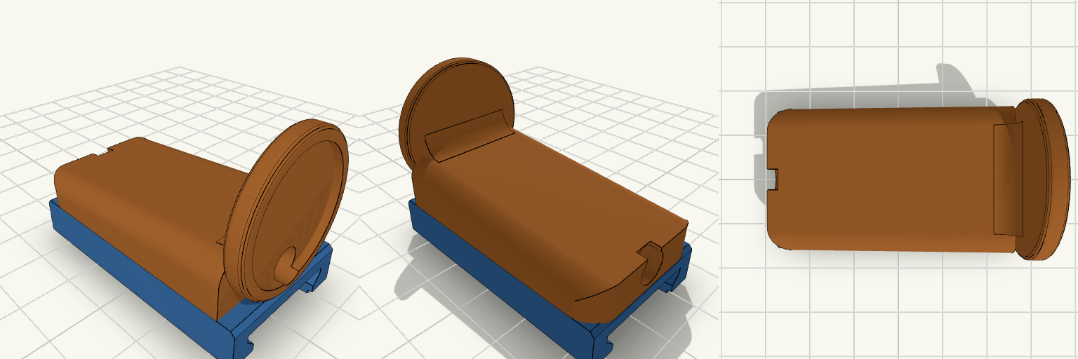
Module pour rail 17,76 mm avec passage de fils
Ce module réunit une base à glissière et un corps supérieur plein et fermé. La base se glisse par l'extrémité d'un rail de 17,76 mm sans vis : deux lèvres à 45° s'engagent dans le col du rail. L'écart entre les lèvres est de 17,76 mm, avec un jeu d'environ 0,2 mm sur la largeur du dessus du rail (21,17 mm). Elle est dimensionnée pour un col de 17,76 mm ; sur un col de 16 mm, elle serait lâche. Le corps supérieur fait 50 mm de long. Une seule extrémité conserve une collerette de Ø28 mm sur 3,5 mm d'épaisseur, avec un contour en relief de 2,24 mm de large sur sa face extérieure : le centre est creusé de 1,5 mm et l'arête extérieure est arrondie à 1 mm, ce qui laisse environ 2 mm de matière au fond du creux. Entre cette collerette et l'autre bout, le corps est aplati et plein, large de 28 mm, avec le dessus arrondi et une pente inclinée qui passe d'environ 11 mm de haut près de la collerette à environ 6,9 mm à l'extrémité basse. Un canal de Ø6 mm traverse toute la longueur pour le passage des fils ; il reste droit et dispose d'environ 2,5 mm de matière au-dessus de la base. À l'extrémité basse, le haut du canal affleure la surface et s'ouvre sur quelques millimètres, dans la zone de la fente. Une fente de 4 mm de large relie ce canal au-dessus de la partie plate ; dans le sens de la longueur, une rampe de même largeur guide les fils depuis le bout bas vers le centre de la pièce et s'arrête à environ 3,5 mm du bout plat, avec une pente d'environ 71°. Le corps ne comporte pas d'alésage central pour un module laser, seulement ce canal et cette fente. Un renfort concave de rayon 4 mm relie la face intérieure de la collerette au-dessus de la partie plate, sans dépasser le Ø28. Il s'étend sur environ 4 mm le long du tube, mesure 20 mm de large, n'atteint pas les côtés de la partie plate et ses arêtes latérales sont arrondies à 6 mm. Les deux coins verticaux du bout bas sont arrondis à 5 mm et les arêtes longitudinales de la pente à 4 mm ; les arêtes du dessus au bout bas restent vives de part et d'autre de la fente. À l'impression : Imprimer la pièce retournée : la face du dessus de la base forme alors un pont de 21 mm. Vérifier l'écart des lèvres sur le premier exemplaire avant de lancer une série : c'est lui qui règle le maintien sur le rail. Le renfort reste dans le Ø28 de la collerette et ne crée pas de débord latéral. La rampe très courte et raide peut forcer sur les fils ; le canal de Ø6 mm limite la matière disponible à l'extrémité basse. Le modèle n'a pas été imprimé ni essayé sur un rail réel ; un léger écart de retrait suffit à changer le glissement.
Tacómetro muscle car de 127 mm
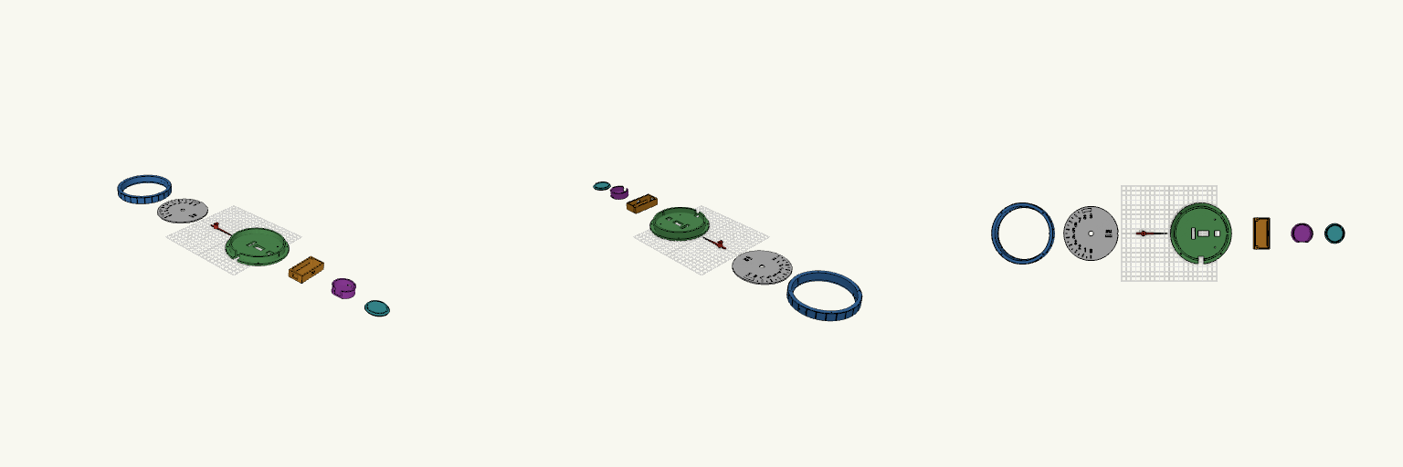
Un tablero de estilo muscle car a escala grande: 127 mm de diámetro exterior, con la esfera estriada, el dial negro de números grandes y una aguja fina de punta afilada que evocan los tacómetros AutoMeter de los tableros deportivos. La escala barre de 0 a 9.000 RPM en 180° —de las 6 a las 12 en sentido horario— y la zona roja arranca en 8.000 RPM. Detrás del dial va un servo SG90, así que la aguja se mueve de verdad, y el conjunto no lleva carcasa trasera. El dial mide 113 mm y deja 109 mm de ventana visible: números, marcas y zona roja escalan con el aro para que la aguja llegue a las marcas. El conjunto se imprime en siete piezas separadas y sin soportes: Aro frontal: 127 mm de diámetro, labio de 2 mm, estrías exteriores y cuatro agujeros para tornillos M3. Lleva una llave de orientación para el dial y dos agujeros piloto a las 12, a ±6 mm del centro, para la luz flash de corte de RPM. Dial: disco de 113 mm con los números 0–9 y los textos «RPM» y «x1000» pasantes de lado a lado —con puentes finos de 0,8 mm que sostienen las islas interiores—, marcas cada 500 RPM y zona roja en relieve. El agujero central es de 10 mm más 0,3 mm de juego de encastre. Aguja: perfil fino de aguja real, con puntero de 50 mm que se angosta desde 1,2 mm hasta unos 0,6 mm en la punta y una cola de contrapeso corta; el cubo central es de 10 mm para dejar el dial despejado. Se monta en el brazo del servo recortado a 12 mm de radio y se fija solo con el tornillo central de 3,2 mm, sin pasador. Soporte servo: placa de 4 mm con ventana para el SG90, dos agujeros piloto para la brida, muesca de llave y ventana de 12 × 12 mm para el cable del servo. Se fija al aro con cuatro tornillos M3 y recibe la caja de ESP32 con dos tornillos M3 desde adelante, con los agujeros a ±29 mm. La ventana del servo mantiene las medidas compactas del SG90. Caja ESP32: pieza aparte de 31 × 65 × 16 mm para una placa de 30 pines de unos 51 × 26 mm, con ranura para el USB, dos rieles internos que sostienen la placa y salida de cable hacia el soporte; se adosa al soporte del servo y queda por detrás. Caja de LEDs: cilindro de 41 mm de diámetro y 14,8 mm de alto, con paredes y fondo de 2 mm y cámara abierta hacia el frente. Va a las 12, con el borde curvado apoyado en el aro, y se fija con dos tornillos M3 horizontales a ±6 mm del centro; la salida del cable de la tira LED está en la pared trasera. Quedan unos 37 mm libres en el interior, suficientes para un LED o un tramo corto de tira. Tapa difusora: disco de 41 mm con solo 1,2 mm de piel, con un anillo guía que entra con 0,3 mm de juego. Es fina para que pase la luz y se imprime con la cara exterior hacia abajo; puede imprimirse en el color del flash —rojo, azul o blanco— en PLA translúcido o natural. Notas de armado y acabado: Los números pasantes dejan pasar la luz de atrás: se puede colocar un filtro de otro color detrás del dial y cambiar el tono de la iluminación. Los puentes se ven como una línea fina en medio de cada número: un puente vertical en el 0 y el 8, uno horizontal en el 4, el 6 y el 9, y otro horizontal sosteniendo la R, la P y los ceros de «RPM x1000». Es lo normal en un estilo stencil. El centro de 10 mm deja paredes de unos 0,9 mm en el cubo de la aguja; conviene imprimir esa zona con 100 % de relleno. Las marcas y la zona roja van en relieve en el mismo archivo que el disco: para cambiar su color hay que pausar la impresión en el cambio de capa. La tira LED no tiene soporte interno: se pega con su adhesivo en la pared interior de la caja de LEDs. Al montar, alineá el brazo del servo en 0° apuntando a las 6 y comprobá la altura del brazo sobre la brida en tu SG90 antes de cerrar el conjunto.
Bay windows for shops
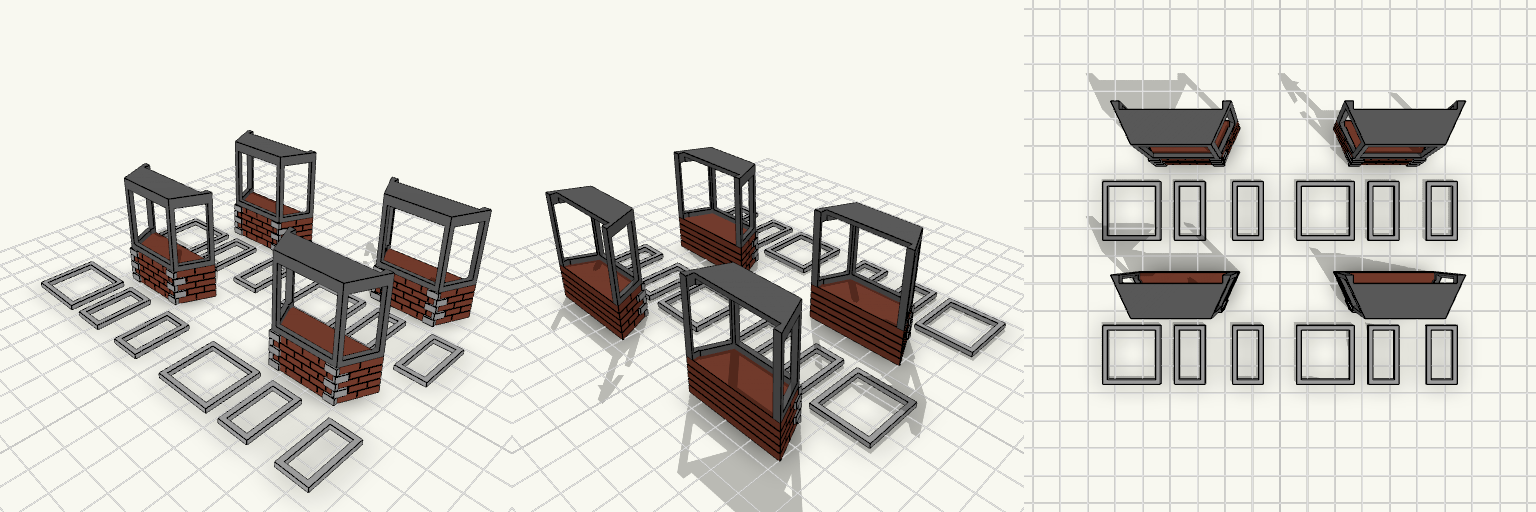
OO scale bay window body, 36 mm wide, 13 mm deep and 40 mm high, with 13 mm of brickwork at the base and three window openings above. Three open window frames print separately on the plate for painting and gluing into the openings. Scale: OO gauge (4 mm to 1 ft) Overall size: 36 × 13 × 40 mm Brickwork: 13 mm high, horizontal courses with staggered joints Front window: 24 mm wide opening; two angled side windows about 14.3 mm wide Frames: 1.6 mm thick with 1.6 mm borders and a through-opening Fit: frames sized with clearance to their openings Back: open, for gluing to a wall
Gancho de Garrafa com Braçadeira Snap
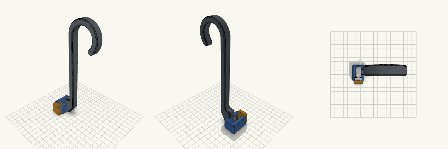
Gancho de garrafa de treino em J, 200 mm, com braçadeira bipartida na base: corpo fixo ligado à haste e tampa separada que fecha por encaixe de pressão ao redor da alça de 12 × 24 mm. Pontos de remix Snap-fit: ganchos flexíveis de 8 mm de comprimento, 1,8 mm de espessura e ressalto de 0,6 mm (armlen, armt, ridge). Entrada em rampa, retenção reta. Folga: 0,2 mm entre tampa e corpo (gap). Trava extra: furo M3 em gota atravessando tampa e corpo, com porca sextavada embutida no lado +X. Paredes: wallx (6,4 mm) e wallf (7,5 mm) definem o tamanho externo; reduza se o furo M3 for dispensado. Haste e gancho: inalterados, seção 10 × 14 mm, bojo de 40 mm, boca de 34 mm. Combina com: parafuso M3 e porca M3 (opcionais); imprima corpo e tampa separados em PETG ou PLA.
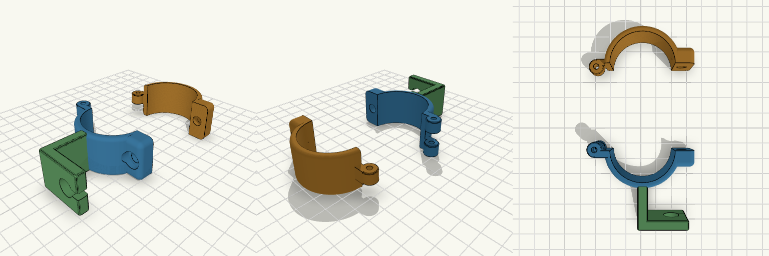
ct1 blinker brackets
A two-piece hinged clamp for a 38.5 mm motorcycle fork tube, with an L-shaped bracket that carries a 10 mm hole and a 4 mm wire slit for a turn signal post. The halves swing open on an M3 hinge pin and close with one M6 bolt and a hex nut pocket, so the fork stays on the bike. The hinge sits outside the ring on small webs, so the knuckles clear the opposite half when it swings. Bore: 38.0 mm Height: 24 mm, wall 3.5 mm Hinge pin: M3 × 30 bolt or 3 mm rod Clamp bolt: M6 with nut Print the front half with its L bracket, and the rear half separately
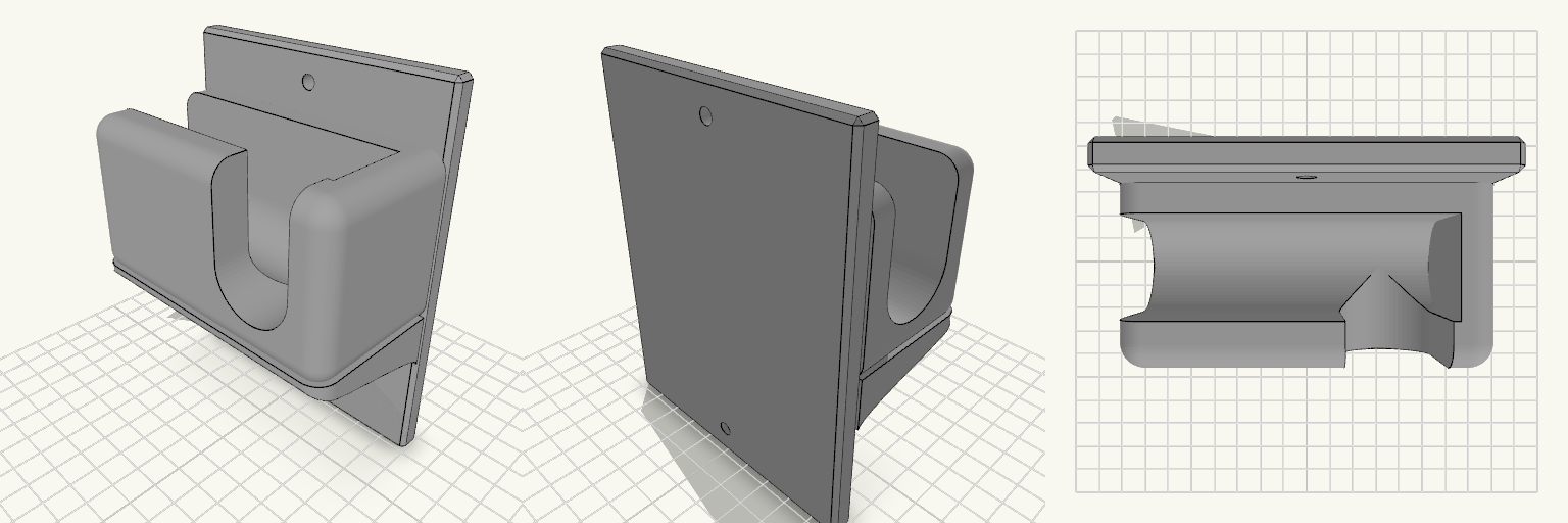
Wall-Mounted Jack Stand Hanger small support
A wall-mounted holder that keeps a 3-ton jack stand off the garage floor and within reach. The flat vertical back plate carries a U-shaped cradle in the centre, open at the top so the stand's bar drops in and lifts out. The cradle is open through the middle and closed by a 10 mm wall at each end, so the bar cannot slide sideways off the holder. The front wall of the cradle is a 13 mm lip that catches the bar and stops it sliding forward. The cradle walls are rounded with a 7 mm radius on every edge except the one against the back plate, and the inner floor is a rounded half-cylinder trough running the length of the opening, 28 mm across to match the seat, so a round bar or handle lies in it without rocking. The holder prints as one piece with no assembly, and it is sized for a 3-ton jack stand and its handle. A compact gusset supports the cradle underneath and runs the full 100 mm width of the cradle, so the end walls sit flush on it instead of overhanging. Its corners carry the same 7 mm radius as the cradle, so the walls run down into it with no ledge. The underside is an S-curve: it leaves the back plate 39 mm up, sweeps out and finishes running straight up the back of the front lip, meeting both surfaces tangentially so there is no crease where it joins. Keep it around this size — trimming it much further leaves the cradle with little support against the weight of a loaded stand. The jack handle hangs from two cuts, so it drops in from above rather than being threaded in from the front. A 28 mm slit in the front wall, open at the top, sits 24 mm right of centre and stays clear of the right edge, which runs fully to the front and stands even with the left wall. Opposite it, the left end wall carries a matching 28 mm notch, open at the top. Both cuts share the cradle trough's floor depth, with their centreline at 80 mm up and their floors bottoming out at 66 mm. The slit floor starts at the trough centreline with a rounded blend where the two meet, so the handle slides from the trough into the slit and notch without a step and hangs clear below. The cradle walls stand 55 mm tall, topping out at 110 mm up, which leaves about 16 mm of wall above a 28 mm handle resting at 80 mm. Overall: 100 mm wide, 130 mm tall, 57 mm deep Cradle: U-shaped, 28 mm bar seat, open top, open through the middle, 10 mm end wall each side, rounded floor trough Cradle walls: 55 mm tall, tops at 110 mm, rounded at 7 mm Bar opening: about 80 mm between end walls Front lip: 13 mm thick Handle slit: 28 mm, open at the top, set 24 mm right of centre in the front wall, floor blended into the trough Left end wall: matching 28 mm notch, open at the top, for the other side of the handle Floor height: slit, notch and trough all bottom out at 66 mm Gusset: full cradle width, 7 mm rounded corners, S-curve underside tangent to the back plate and the front lip, meeting the plate 39 mm up Mounting: one countersunk screw hole above the cradle and one below; use 5 mm or larger screws into a stud or suitable anchor Material: grey PETG suits the load and garage conditions; edges are chamfered Check that the stand's bar fits the 28 mm seat and the 80 mm opening, and that the handle fits the 28 mm slit and notch before printing. If the bar or handle is larger, widen the seat or the cuts to match.