3D-printable automotive, RC & hobby parts
Car inserts, RC bumpers, slot-car bodies, drone guards and hobby parts with real dimensions. Browse what makers built, or describe the exact part you need and Printy makes it.
Need one that fits your exact measurements? Start building →
Newest
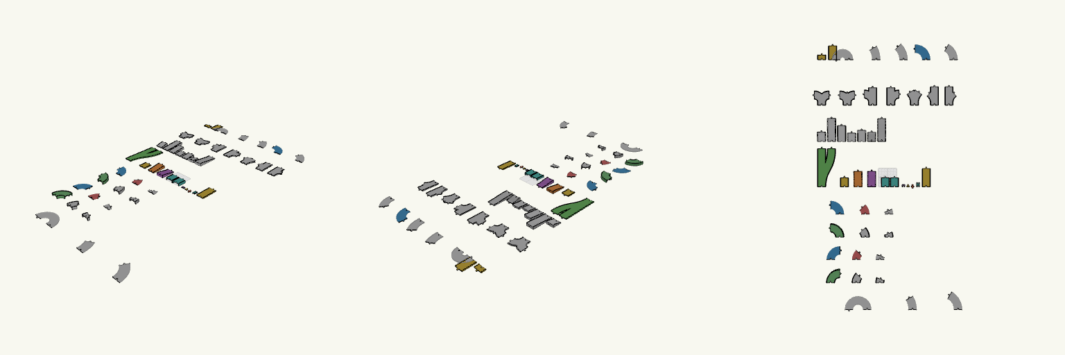
250 mm Bed RC Track Pieces, 90 mm Lane
Straight and curved RC track pieces sized to fit a 250 x 250 mm print bed, using the same 90 mm wide track and bulb-and-socket latch as the rest of the set. What it fits Built for printers with a 250 x 250 mm bed or larger. Mates with the existing 90 mm wide pieces (80 mm clear lane, 5 mm rails) through the same latch with 1 mm clearance. Pieces Straights: 50 mm and 150 mm (the 200 mm straight also fits). 180° hairpin at 70 mm centreline radius, about 230 mm wide. 30° at 250 mm radius, 45° at 200 mm, 60° at 150 mm, 90° at 120 mm. Check before printing The footprint of each piece is measured from the model, but measure your bed's usable area, since brims and clips reduce it. Does not fit The earlier 180° hairpin at 100 mm radius, the main junction (about 440 mm) and the multi-way junctions are larger than a 250 mm bed. The latches have not been test-fitted.
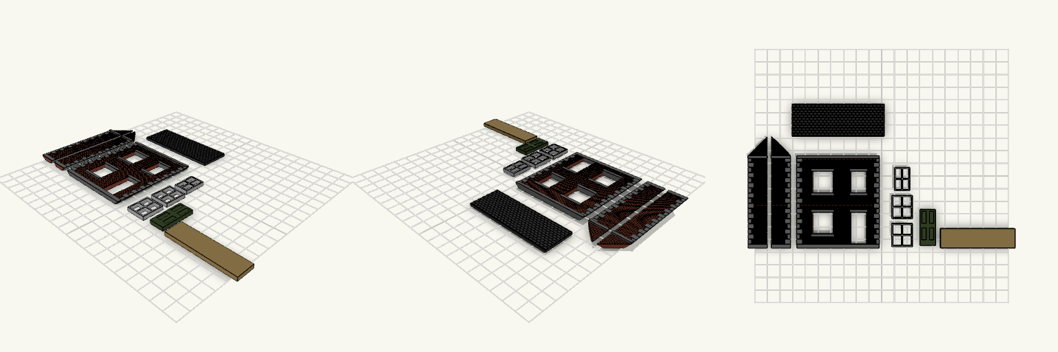
OO Gauge Terraced House Kit with gable end not good
A half-relief take on a Victorian terraced house in OO gauge: brick front with quoins, mitred corners and a roof that pitches back at 45° from the eaves, like the shop-front buildings that sit flat against a layout backscene. The side walls rise in a 45° slope to meet the roof, and the two tiled roof panels are sized to overhang the front and both sides. Brick front with separate window and door inserts Two mirrored side walls, 15 mm deep, with sloped tops Floor piece spanning between the sides Two tile-pattern roof panels, 36 × 25 mm each 45° mitred corner joins
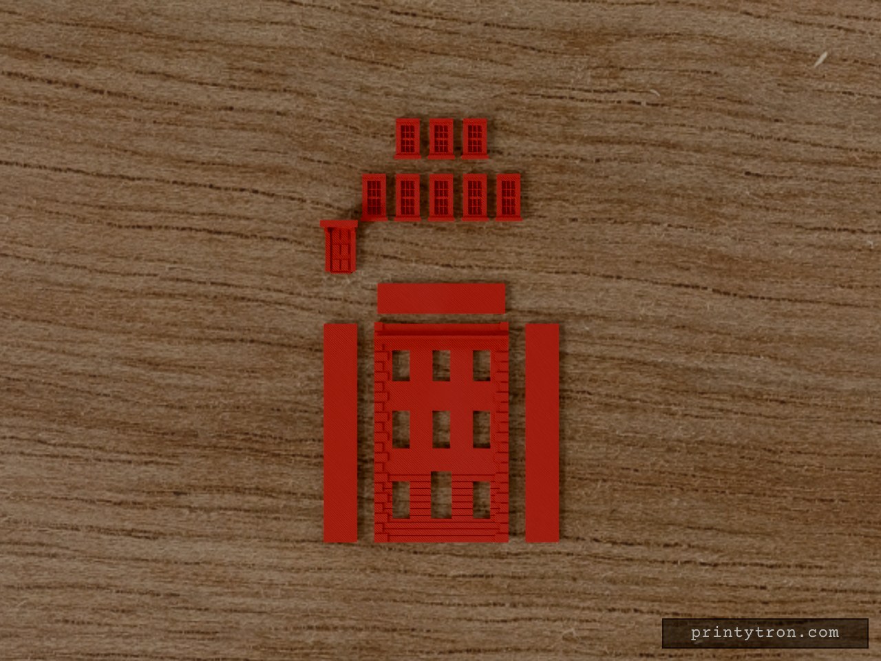
OO Scale Georgian Townhouse Facade
A flat-pack 4mm/OO scale Georgian townhouse half-relief facade. Features separate drop-in windows and a six-panel door with an ornate canopy hood, plus 45-degree mitered side walls for a seamless glued corner finish. What it's for Designed for model railway backdrops and dioramas, this building prints flat to minimise print time and eliminate the need for supports. The individual pre-coloured inserts allow you to paint the facade and glazing separately before dropping them into place. Dimensions Scale: 1:76 (OO Gauge) Assembled Footprint: 76 mm wide × 18 mm deep Facade Height: 130 mm (Three storeys) Print notes Supports: None required. The canopy and all window frames are designed to print vertically from the build plate. Fitment: The window and door cutouts are oversized by 0.5 mm for an easy drop-in fit. Use standard plastic cement or superglue on the rear locator blocks.
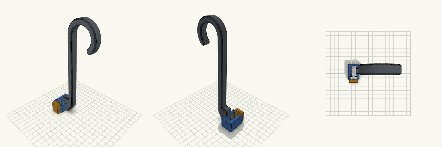
Gancho de Garrafa com Braçadeira Snap
Gancho de garrafa de treino em J, 200 mm, com braçadeira bipartida na base: corpo fixo ligado à haste e tampa separada que fecha por encaixe de pressão ao redor da alça de 12 × 24 mm. Pontos de remix Snap-fit: ganchos flexíveis de 8 mm de comprimento, 1,8 mm de espessura e ressalto de 0,6 mm (armlen, armt, ridge). Entrada em rampa, retenção reta. Folga: 0,2 mm entre tampa e corpo (gap). Trava extra: furo M3 em gota atravessando tampa e corpo, com porca sextavada embutida no lado +X. Paredes: wallx (6,4 mm) e wallf (7,5 mm) definem o tamanho externo; reduza se o furo M3 for dispensado. Haste e gancho: inalterados, seção 10 × 14 mm, bojo de 40 mm, boca de 34 mm. Combina com: parafuso M3 e porca M3 (opcionais); imprima corpo e tampa separados em PETG ou PLA.
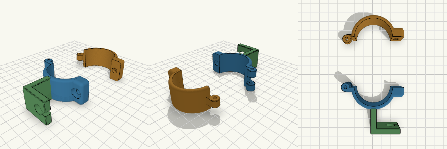
ct1 blinker brackets
A two-piece hinged clamp for a 38.5 mm motorcycle fork tube, with an L-shaped bracket that carries a 10 mm hole and a 4 mm wire slit for a turn signal post. The halves swing open on an M3 hinge pin and close with one M6 bolt and a hex nut pocket, so the fork stays on the bike. The hinge sits outside the ring on small webs, so the knuckles clear the opposite half when it swings. Bore: 38.0 mm Height: 24 mm, wall 3.5 mm Hinge pin: M3 × 30 bolt or 3 mm rod Clamp bolt: M6 with nut Print the front half with its L bracket, and the rear half separately
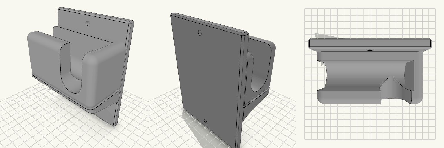
Wall-Mounted Jack Stand Hanger small support
A wall-mounted holder that keeps a 3-ton jack stand off the garage floor and within reach. The flat vertical back plate carries a U-shaped cradle in the centre, open at the top so the stand's bar drops in and lifts out. The cradle is open through the middle and closed by a 10 mm wall at each end, so the bar cannot slide sideways off the holder. The front wall of the cradle is a 13 mm lip that catches the bar and stops it sliding forward. The cradle walls are rounded with a 7 mm radius on every edge except the one against the back plate, and the inner floor is a rounded half-cylinder trough running the length of the opening, 28 mm across to match the seat, so a round bar or handle lies in it without rocking. The holder prints as one piece with no assembly, and it is sized for a 3-ton jack stand and its handle. A compact gusset supports the cradle underneath and runs the full 100 mm width of the cradle, so the end walls sit flush on it instead of overhanging. Its corners carry the same 7 mm radius as the cradle, so the walls run down into it with no ledge. The underside is an S-curve: it leaves the back plate 39 mm up, sweeps out and finishes running straight up the back of the front lip, meeting both surfaces tangentially so there is no crease where it joins. Keep it around this size — trimming it much further leaves the cradle with little support against the weight of a loaded stand. The jack handle hangs from two cuts, so it drops in from above rather than being threaded in from the front. A 28 mm slit in the front wall, open at the top, sits 24 mm right of centre and stays clear of the right edge, which runs fully to the front and stands even with the left wall. Opposite it, the left end wall carries a matching 28 mm notch, open at the top. Both cuts share the cradle trough's floor depth, with their centreline at 80 mm up and their floors bottoming out at 66 mm. The slit floor starts at the trough centreline with a rounded blend where the two meet, so the handle slides from the trough into the slit and notch without a step and hangs clear below. The cradle walls stand 55 mm tall, topping out at 110 mm up, which leaves about 16 mm of wall above a 28 mm handle resting at 80 mm. Overall: 100 mm wide, 130 mm tall, 57 mm deep Cradle: U-shaped, 28 mm bar seat, open top, open through the middle, 10 mm end wall each side, rounded floor trough Cradle walls: 55 mm tall, tops at 110 mm, rounded at 7 mm Bar opening: about 80 mm between end walls Front lip: 13 mm thick Handle slit: 28 mm, open at the top, set 24 mm right of centre in the front wall, floor blended into the trough Left end wall: matching 28 mm notch, open at the top, for the other side of the handle Floor height: slit, notch and trough all bottom out at 66 mm Gusset: full cradle width, 7 mm rounded corners, S-curve underside tangent to the back plate and the front lip, meeting the plate 39 mm up Mounting: one countersunk screw hole above the cradle and one below; use 5 mm or larger screws into a stud or suitable anchor Material: grey PETG suits the load and garage conditions; edges are chamfered Check that the stand's bar fits the 28 mm seat and the 80 mm opening, and that the handle fits the 28 mm slit and notch before printing. If the bar or handle is larger, widen the seat or the cuts to match.
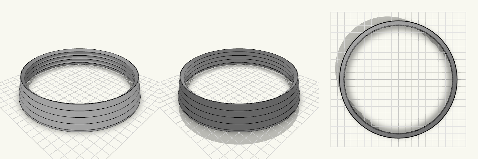
TPU Speaker Bellows Ring
Round bellows ring that seals a 6.5" car door speaker so sound is directed into the cabin instead of the door panel. Designed for single-perimeter TPU printing. 168 mm base diameter to clear the mounting screws 155 mm top opening 32 mm overall height with four pleats 0.45 mm wall, one perimeter 2.4 mm flat base flange Slice with a single perimeter (vase mode or equivalent) and check that the slicer keeps the pleat folds.
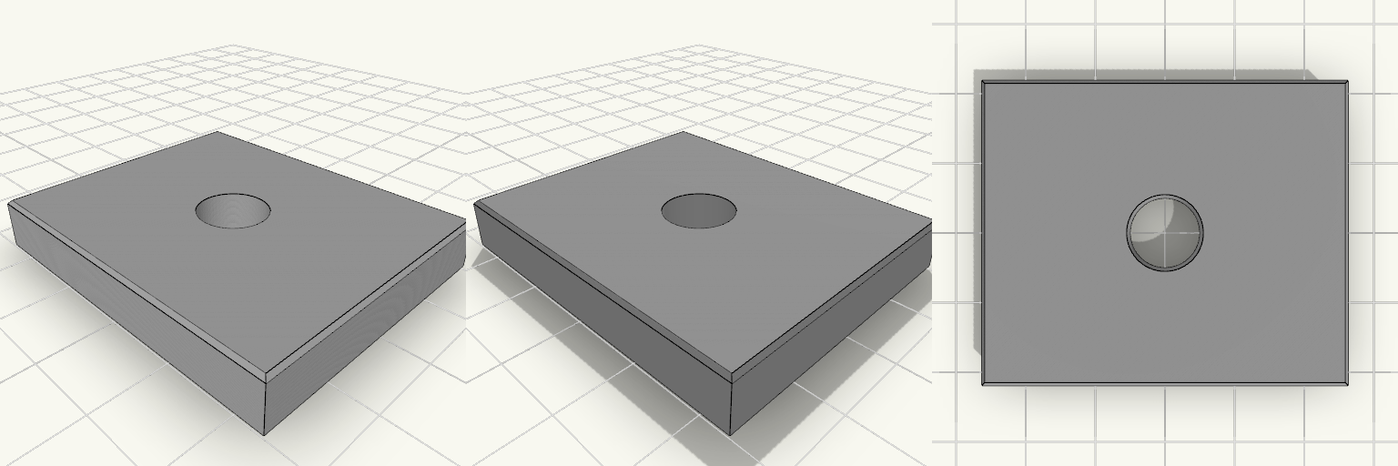
Elliptical Pedal Center Insert
A 48 × 40 × 7 mm replacement insert for the broken center of an elliptical trainer pedal. Flat top, 10 mm through-hole, 20 mm full-height boss, and a ribbed underside. Remix hooks Footprint (48 × 40 mm): the main value to tune to the pedal pocket; rim, ribs and diagonals follow it. Top edge chamfer (0.5 mm): set to 0 for a fully tight seam. Hole (10 mm) and boss (20 mm): change for a different axle or bolt; a wider boss adds strength. Underside depth (3 mm): rim and ribs can be taller or thinner, with the top plate at 4 mm. Pairs with: countersunk screws or adhesive through the boss area.
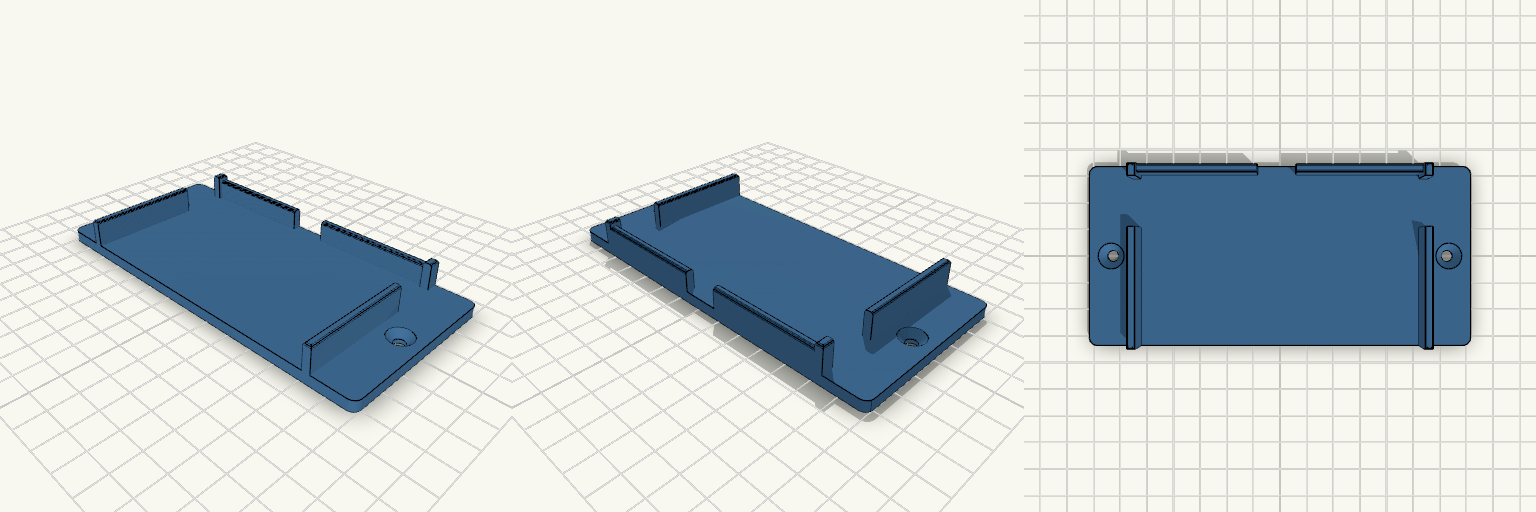
Triple Socket Adapter Floor Cradle
What it's for A one-piece floor cradle that holds a triple 12V socket adapter horizontally under a dashboard. The front and top stay open, so the sockets and power switches remain reachable, and side windows keep the side USB ports clear. Dimensions Adapter: 100.4 x 60.85 x 31.72 mm, about 1 mm clearance Side walls: 3 mm thick, 14 mm tall Side windows: 18 mm long, centred 51.38 mm from the front (plus 1 mm clearance) Back lip: 12 mm tall with reinforced corners Mounting ears: 16 mm each end, countersunk screw holes Remix ideas Change the window length to fit a different USB port. Add a third screw hole at the back. Lengthen the ears for wider mounting.
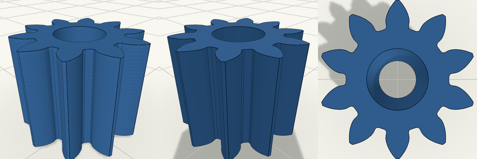
10-Tooth Module 0.5 Spur Gear
What it's for A small straight-cut involute spur gear for miniature gear trains, hobby motors and small mechanisms. It is a single solid body with a bore that passes fully through. Dimensions Teeth: 10 Module: 0.5 mm (pitch diameter 5 mm) Outside diameter: 6 mm Pressure angle: 20° Bore: 2.5 mm, through Face width: 5 mm Remix ideas Pair it with a larger module 0.5 gear for a reduction stage. Add a set-screw hub for a motor shaft. Swap the round bore for a D-shaped one.
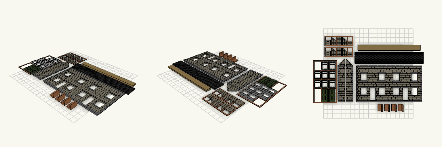
OO Gauge semi detached house stone v2
A semi-detached OO gauge house pair with stone walls, a one-piece roof, separate door and window inserts, and chimneys supplied as flat-pack panels. The two 72 mm frontages sit side by side (144 mm overall) with quoins only at the outer ends. Each chimney is four panels plus a capped top, printed flat and joined by a thin 0.4 mm web. A second web holds the windows and door together on the plate. Remix hooks Chimney slope: side panels run 9 to 18 mm high at 45°. Change the two heights to suit a different roof pitch. Panel thickness: 1.5 mm. Thicker panels give stronger glue joints. Web: 0.4 mm tall with 1.2 mm bars. Cut it away after printing, or thin it further. Pairs with: the L-shaped corner brackets (10 × 10 mm legs, 15 mm long) for gluing the walls square.
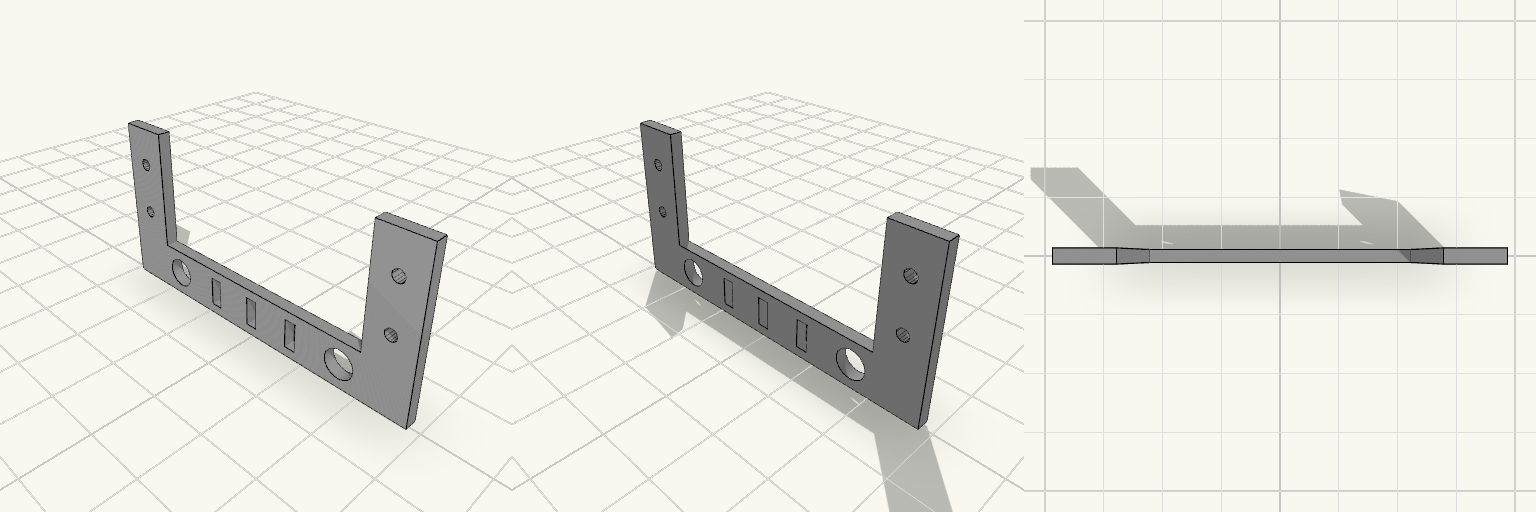
Lumiere araignee
Support en U pour une lumière de téléguidage montée sur servo. La base est debout sous les deux pattes et les porte sur toute leur largeur ; les pattes repartent vers le haut depuis le dessus de la base. Chaque patte est tournée de 90° autour de son axe vertical : 8 mm en X et 2 mm d’épaisseur en Y. La base reçoit deux trous de 5 mm à environ ±17 mm de l’axe, et chaque patte deux trous de 2 mm à 5 mm et 13,5 mm de son bas. Entre les deux trous de 5 mm, la base est ajourée d’une grille de trois fentes de 2 mm de large sur 5 mm de haut, une centrale et deux à ±8 mm, traversant l’épaisseur en Y. L’espace intérieur entre les pattes est réduit de 7,4 mm, ce qui ramène la base à 56,8 mm de long. Caractéristiques Encombrement hors tout : 56,8 × 2 × 27,6 mm (X × Y × hauteur). Base : 56,8 mm en X, 8 mm de haut, 2 mm d’épaisseur en Y ; debout sous les pattes. Pattes : 19,6 mm de haut, 8 mm en X, 2 mm en Y, aux deux extrémités en X, à partir du dessus de la base. Espace entre pattes : réduit de 7,4 mm ; les pattes restent aux extrémités de la base. Perçages des pattes : deux trous de 2 mm par patte, traversant l’épaisseur en Y, à 5 mm et 13,5 mm du bas des pattes. Perçages de base : deux trous de 5 mm à ±17 mm de l’axe, traversant l’épaisseur en Y. Grille de base : trois fentes de 2 mm de large sur 5 mm de haut entre les trous de 5 mm, à −8, 0 et +8 mm, traversant l’épaisseur en Y. Jeu : prévoir quelques dixièmes de jeu dans les trous de 5 mm si les vis doivent rester libres.
Ladeo — Prensa Lateral Servoaccionada para G-Seat
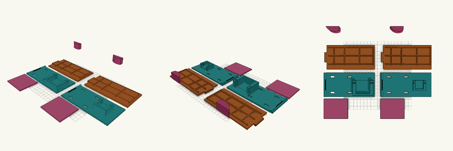
Ladeo es una prensa lateral servoaccionada para un G-Seat de simulador de carreras. La versión actual incluye dos montajes completos lado a lado: uno para Futaba S3003 y una copia para SG90, con las mismas placas, bisagra y leva, y una cuna distinta para cada servo. Se entrega en despiece, con cada pieza apoyada en la cama, para imprimir y montar como un apoyo lateral acolchado que cierra contra el cuerpo, al estilo del sujetariñones de una silla. La bisagra va montada en el extremo corto de la placa. Piezas del despiece Placa fija con bisagra: lleva la bisagra de pasador de 2 mm en el extremo corto, las 4 ranuras de fijación (X 25 y 75, Y 12 y 58) y la cuna del servo. Hay dos copias lado a lado; el conjunto de placas fijas ocupa unos 313 × 70 mm en la cama. Placa móvil con refuerzos: placa de 3 mm con venas de 2 mm de ancho por 4 mm de alto: 3 longitudinales y 4 transversales. Hay dos copias. En el despiece va plana; la inclinación de reposo no está aplicada. Acolchado: pieza aparte de 3 mm de espesor, una por montaje. Leva: perfil cilíndrico recortado; se imprime acostada sobre su cara lateral. No trae cubo ni agujero para el eje o la cruceta del servo. Soportes de servo Cunas: las dos comparten paredes laterales con 0,3 mm de holgura, tope trasero, base elevada para dejar el eje a Z 13, muesca para las orejas y dos agujeros guía de 2,5 mm para tornillos autorroscantes. Futaba S3003: cuerpo de 40,4 × 19,8 × 36,5 mm, orejas de 55,5 mm y agujeros a 49,5 mm. SG90: cuerpo de 22,7 × 12,2 × 22,7 mm, orejas de 32,5 mm y agujeros a 27,5 mm. En esta copia el cuerpo queda desplazado 5,5 mm del eje, frente a 10,2 mm en el Futaba; la posición del eje de la leva no cambia. Las alturas de las orejas son estimadas: prueba el servo real en la cuna antes de imprimir. Mecanismo La bisagra es fina: cilindro de 5,5 mm y pasador de 2 mm, con el eje en el extremo corto de la placa, a X≈5, a lo largo de Y y a Z≈4. La placa fija lleva dos nudillos (Y 0–20 y 50–70) y la placa móvil uno entre ellos (Y 21–49), con 0,3 mm de holgura. La placa móvil se abre levantando el extremo opuesto a la bisagra, hacia X≈148; el servo y la leva quedan cerca de ese extremo libre. La leva es un cilindro de 50 mm con la parte posterior atenuada y un ancho de 18 mm en Y; empuja por debajo de la placa móvil, cerca de la zona opuesta a la bisagra. Gira de 0° a 90°, en reposo queda girada 43° hacia abajo, y a 90° el punto más alto sube unos 30 mm sobre el reposo, no los 40 mm de una carrera ideal. Con la bisagra en el extremo corto, la leva empuja cerca del extremo libre, la zona que más sube, así que la apertura real puede variar; conviene comprobar que la placa abierta no roce la cuna del servo. El contacto es aproximado porque la punta arrastra sobre la placa; un rodillo o una ranura en la placa móvil daría un contacto más preciso. Montaje y ajuste Para que apriete el cuerpo, la placa móvil debe quedar del lado de la persona. No lleva resorte de retorno: hace falta una banda elástica entre las placas o que el propio cuerpo devuelva la placa. No tiene topes ni protección contra sobrepresión; el límite lo marcan la forma de la leva y el contacto con la placa. Verifica las 4 ranuras contra el sujetariñones real, la altura del eje del servo y las holguras de la bisagra antes de imprimir. Revisa que el pasador de 2 mm salga limpio, que la placa móvil gire sin forzar, que la placa abierta no roce la cuna y que la leva pase libre y quede dentro de la placa.
Technic Plate 2x4 With Holes, Set of 6
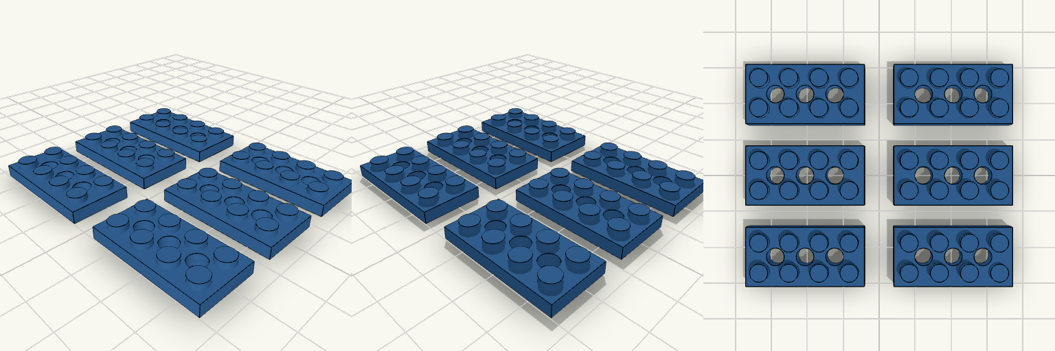
A 2x4 plate with no way to pass a Technic pin or axle through it is a dead end in a studless build. This plate has three holes on the centre line, so pins and axles go straight through. Six are laid out flat for one print run. Key numbers Plate: 32 x 16 mm, 3.2 mm thick, studs on 8 mm pitch Studs: 4.8 mm diameter, 1.8 mm tall Holes: three, 4.8 mm diameter, on the centre line, 8 mm apart Print: flat, no supports, 0.2 mm layers; test one first to check clutch fit
Pinch-Feed Drive Roller, Print-Ready
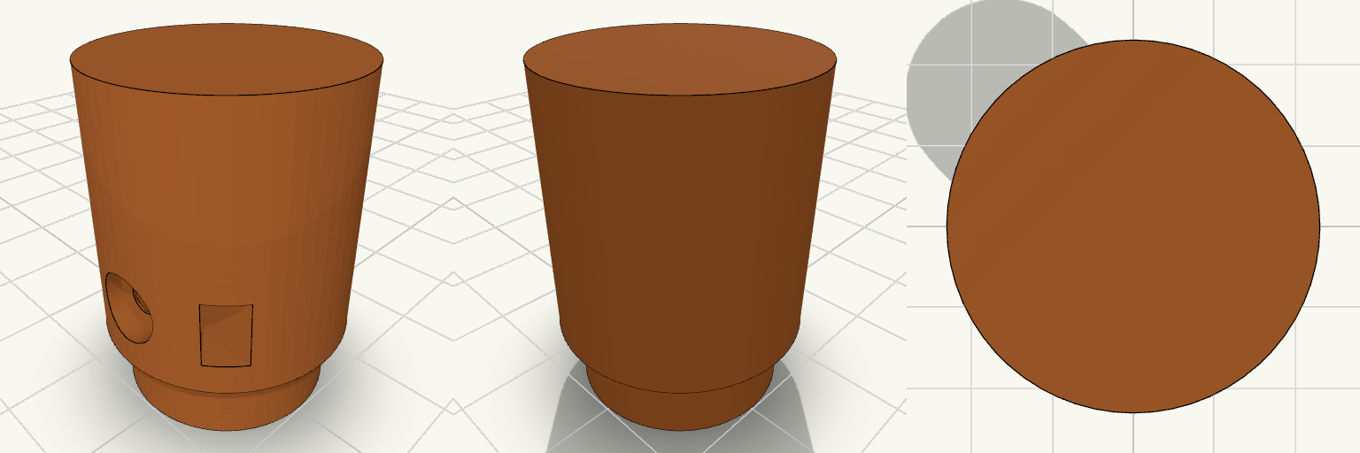
A knurl-free drive wheel for a pinch-feed wire feeder, built like a small industrial pulley: a 24 mm roller with a hub on one side and a blind D-bore that slips over a 5 mm D-shaft. The model is just the roller, standing on its hub and ready to slice. Design notes Blind D-bore, open on the hub face and closed by a wall on the far end, so the closed end shows which side stays out. M3 grub screw hole with a trapped hex nut that slides in through a slot open to the rim. Counterbored screw recess 2 mm deep, so a headed M3 screw sits below the surface and a nylon or TPU sleeve goes on smooth. Hub spaces the roller off the motor face so the two do not rub. Printing Stands on the hub with the bore opening onto the bed, so there is no bridging inside the bore and no supports are needed. Printing upright keeps the roller round. Suggested: PETG, ASA or nylon, 3 or more walls, 25–30% infill.
Slim Sun Visor Mirror Frame
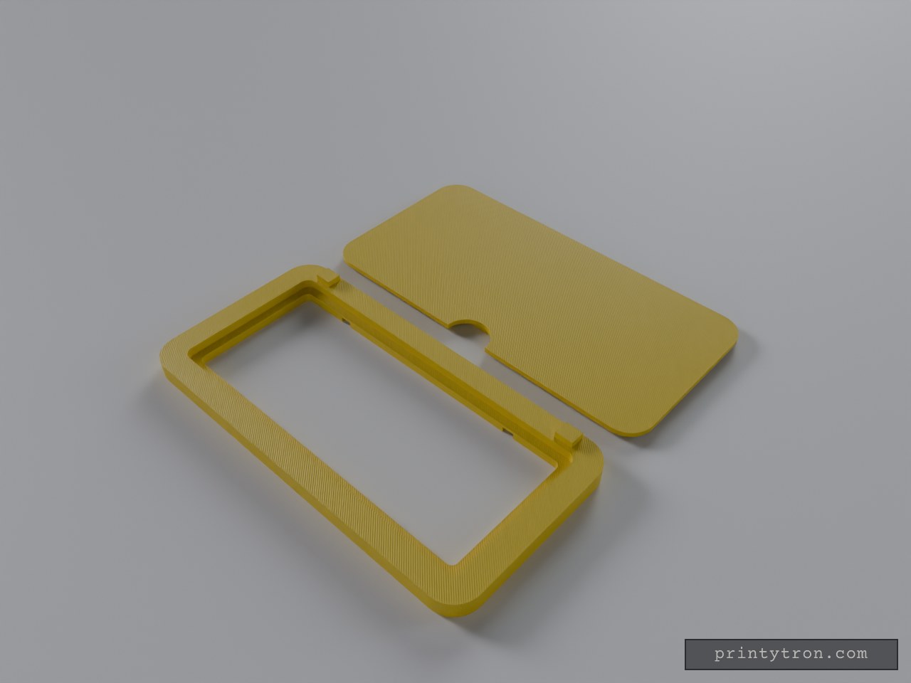
A flat, rounded-corner frame for a sun visor vanity mirror, with a separate thin protective lid. Glass is supplied by you. Body: 130 x 65 x 6 mm, 9 mm corner radius Glass pocket: 114 x 50 mm, 3 mm deep Rear strap slots: two slots for a hook-and-loop or elastic strap around the visor, so no clips show Lid: 1.8 mm plate with an underside lip that press-fits into the pocket, plus a front thumb notch Printed as two separate pieces, no supports needed when printed flat Adjust the pocket size to match your glass before printing.
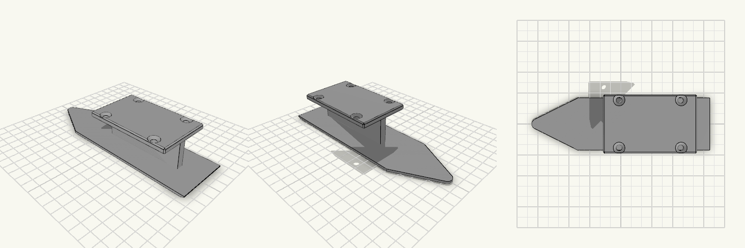
Schneekufe für Skateboard, Truck-Lochbild 53 × 41 mm
Schneekufen für Skateboards, die auf Schnee und Eis gefahren werden. Die Kufe wird über das Truck-Lochbild an der Achsaufnahme verschraubt und sorgt für Führung auf glatten Untergründen. Die Sohle ist 170 mm lang, 50 mm breit und 2 mm dick; der mittlere Steg ist 6 mm dick. Die Sohle ist über die gesamte Länge flach ausgeführt. Montageplatte, Steg und Lochbild sitzen 25 mm zum hinteren, breiten Ende hin versetzt, sodass der Steg voll auf dem flachen Teil der Sohle steht. Das vordere Ende verjüngt sich geradlinig zu einer etwa 10 mm breiten, leicht gerundeten Spitze; das gegenüberliegende Ende bleibt breit. Beide Sohlenenden haben eine 3-mm-Fase. Für ein Skateboard sind zwei Kufen nötig. Maße und Montage Gesamtmaß: 170 mm lang, 50 mm breit, 33 mm hoch Sohle: 2 mm dick, durchgehend flach Mittlerer Steg: 6 mm dick, steht voll auf der flachen Sohle Verjüngung: geradlinig zur Spitze, Spitzenbreite etwa 10 mm, leicht gerundet Gegenüberliegendes Ende: breit ausgeführt Enden: 3-mm-Fase an beiden Sohlenrändern Befestigungspunkt: Montageplatte mit Truck-Lochbild 53 × 41 mm, 25 mm zum breiten Ende versetzt Schraublöcher: 5,4 mm, oben angesenkt Befestigung: handelsübliche Schrauben und Muttern Die Maße sind Standardwerte und nicht an ein bestimmtes Board angepasst – vor dem Druck mit dem eigenen Truck-Lochbild abgleichen Druck Passt auf das Druckbett eines A1 mini Durchgehend flache Sohle: kein Stützmaterial an der Spitze nötig 2-mm-Sohle: auf dem A1 mini etwa die Untergrenze; die Sohle wird flexibel und gibt unter Last nach, daher mit mehreren Wandlinien drucken Material: PETG oder ASA Stückzahl: zwei Kufen pro Skateboard
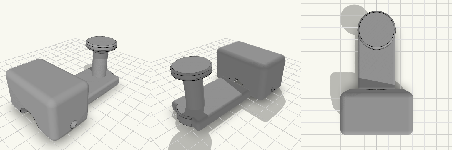
Mountain Bike Wagon Hitch with Capped Post
What it's for A hitch that lets a mountain bike pull a wagon by its C-shaped handle. The bike side is a clamp block that grips the frame tube with a pinch bolt; a flat arm carries that back to an upright post. The post ends in a 12 mm neck with a flared cap on top, so the wagon's C-handle drops over it and cannot slide off while you ride. Clamp block with a 22 mm bore and a single pinch bolt — check this bore against your actual seat stay or axle tube before printing, and scale the clamp if your tube differs Flat arm sets the post behind the clamp, clear of the frame Capped neck holds the handle on but still lifts off when you want to unhitch Dimensions Overall footprint on the plate: 50 × 83 × 38 mm Clamp bore: 22 mm Post neck: 12 mm diameter, about 22 mm tall, with a flared cap above it Print notes Print the part as oriented on the plate so the clamp bore and the neck stay round and the arm keeps its strength across the layer lines. A tough filament such as PETG or ABS/ASA suits a part that takes trail vibration and towing loads better than plain PLA. Remix ideas Resize the clamp bore for thinner or thicker frame tubes, or split the clamp into a two-bolt version for rougher trails Lengthen the arm to move the post further back for wider cargo or tighter frame clearance Swap the capped neck for a ball or pin joint if you want the wagon handle to pivot more freely
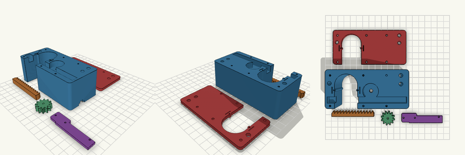
final version 25 mm Paddle Shaft
Motorised rack-and-pinion U-holder for a 30 mm paddle shaft, with hollow flexing snap detents on the slot walls. Fit Host: 30 mm round paddle shaft in a 32 mm slot; N20 gear motor, 12 × 10 mm body, 3 mm shaft. Detents: each slot wall has a hollow bump (1 mm radius through-hole) on a flex finger with a relief slit. The cover plate carries the same features. Not for: shafts other than about 30 mm, or motors with a different body size. Check before printing Measure the N20 body length including gearbox and terminals; the motor length is a parameter. Detent stiffness depends on the bump height and the hole radius. Adjust them for your filament. Parts Housing, sliding rack, pinion, motor retainer and cable cover (one piece), guide cover plate.
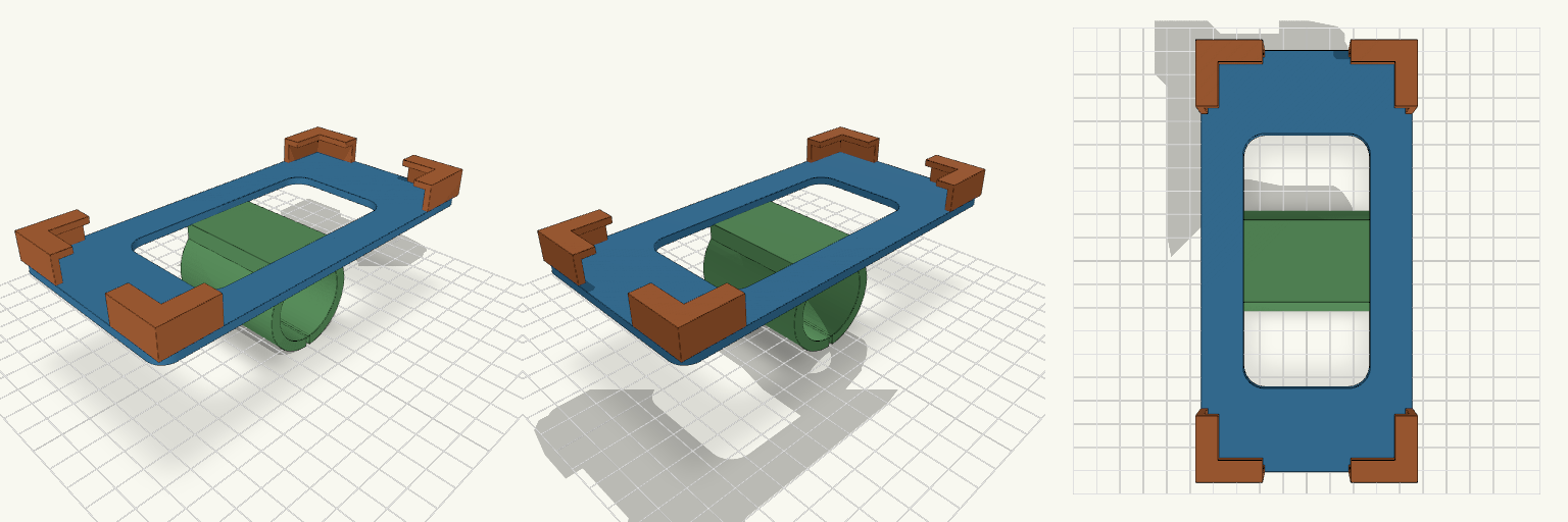
iPhone 15 Pro Bike Mount 31.8mm Bar
Handlebar phone mount sized for the iPhone 15 Pro (146.6 × 70.6 × 8.25 mm). A back plate with a weight-saving window holds the phone, four L-shaped corner clips wrap the edges and hook 4 mm over the screen face, and a split clamp on the back fits 31.8 mm handlebars. The clamp split is present, but no bolt tab or hardware mounting is included yet. A strap or added bolt tab is needed to tighten it on the bar. Specifications Phone: iPhone 15 Pro, 146.6 mm tall, 70.6 mm wide, 8.25 mm thick Pocket: 71.2 × 147.2 mm inside (0.6 mm total clearance) Corner clips: 4, each with 18 mm arms along both edges, 2.4 mm wall, 4 mm lip over the face Back plate: 3 mm thick, 6 mm corner radius, central cutout to reduce weight Clamp: 31.8 mm bore, 4 mm wall, 50 mm wide, split at the bottom Overall size: 76 × 152 mm footprint, about 54 mm tall in the print orientation Print notes: supports needed under the back plate in the modelled orientation; PETG or ASA suggested for heat and vibration Parts: back plate, corner clips, handlebar clamp (single welded body)
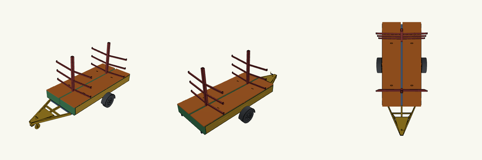
Six Kayak Trailer with Jockey Wheel
A trailer for carrying six kayaks, three per side, on two centre columns with branching support arms. Full-length lockers run along both sides under the kayaks, each with a side door for paddles and life jackets. The A-frame drawbar carries a ball coupler with latch, lever and safety chain, plus a jockey wheel with a tyre, rim, fork and a crank handle on top. Six kayak positions, three per side Two full-length side lockers with side doors Twin wheels with tyres, rims and mudguards A-frame drawbar with cross members, spine and braces Jockey wheel with top crank handle
Tacómetro muscle car de 80 mm
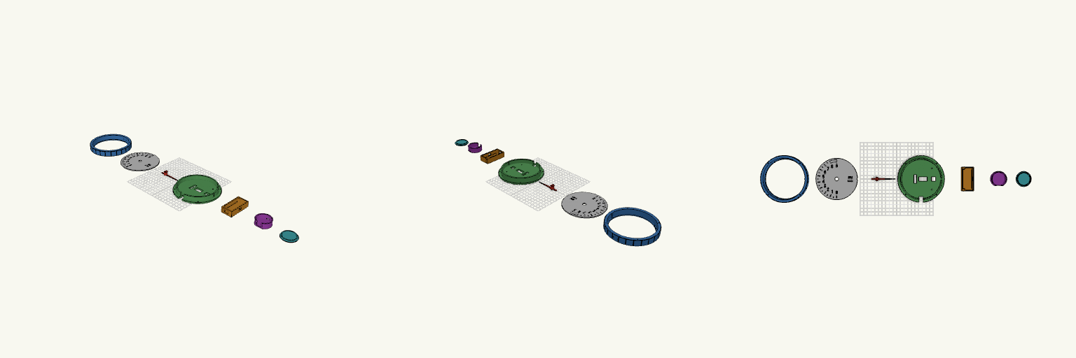
Un tablero de estilo muscle car a escala grande: 127 mm de diámetro exterior, con la esfera estriada, el dial negro de números grandes y una aguja fina de punta afilada que evocan los tacómetros AutoMeter de los tableros deportivos. La escala barre de 0 a 9.000 RPM en 180° —de las 6 a las 12 en sentido horario— y la zona roja arranca en 8.000 RPM. Detrás del dial va un servo SG90, así que la aguja se mueve de verdad, y el conjunto no lleva carcasa trasera. El dial mide 113 mm y deja 109 mm de ventana visible: números, marcas y zona roja escalan con el aro para que la aguja llegue a las marcas. El conjunto se imprime en siete piezas separadas y sin soportes: Aro frontal: 127 mm de diámetro, labio de 2 mm, estrías exteriores y cuatro agujeros para tornillos M3. Lleva una llave de orientación para el dial y dos agujeros piloto a las 12, a ±6 mm del centro, para la luz flash de corte de RPM. Dial: disco de 113 mm con los números 0–9 y los textos «RPM» y «x1000» pasantes de lado a lado —con puentes finos de 0,8 mm que sostienen las islas interiores—, marcas cada 500 RPM y zona roja en relieve. El agujero central es de 10 mm más 0,3 mm de juego de encastre. Aguja: perfil fino de aguja real, con puntero de 50 mm que se angosta desde 1,2 mm hasta unos 0,6 mm en la punta y una cola de contrapeso corta; el cubo central es de 10 mm para dejar el dial despejado. Se monta en el brazo del servo recortado a 12 mm de radio y se fija solo con el tornillo central de 3,2 mm, sin pasador. Soporte servo: placa de 4 mm con ventana para el SG90, dos agujeros piloto para la brida, muesca de llave y ventana de 12 × 12 mm para el cable del servo. Se fija al aro con cuatro tornillos M3 y recibe la caja de ESP32 con dos tornillos M3 desde adelante, con los agujeros a ±29 mm. La ventana del servo mantiene las medidas compactas del SG90. Caja ESP32: pieza aparte de 31 × 65 × 16 mm para una placa de 30 pines de unos 51 × 26 mm, con ranura para el USB, dos rieles internos que sostienen la placa y salida de cable hacia el soporte; se adosa al soporte del servo y queda por detrás. Caja de LEDs: cilindro de 41 mm de diámetro y 14,8 mm de alto, con paredes y fondo de 2 mm y cámara abierta hacia el frente. Va a las 12, con el borde curvado apoyado en el aro, y se fija con dos tornillos M3 horizontales a ±6 mm del centro; la salida del cable de la tira LED está en la pared trasera. Quedan unos 37 mm libres en el interior, suficientes para un LED o un tramo corto de tira. Tapa difusora: disco de 41 mm con solo 1,2 mm de piel, con un anillo guía que entra con 0,3 mm de juego. Es fina para que pase la luz y se imprime con la cara exterior hacia abajo; puede imprimirse en el color del flash —rojo, azul o blanco— en PLA translúcido o natural. Notas de armado y acabado: Los números pasantes dejan pasar la luz de atrás: se puede colocar un filtro de otro color detrás del dial y cambiar el tono de la iluminación. Los puentes se ven como una línea fina en medio de cada número: un puente vertical en el 0 y el 8, uno horizontal en el 4, el 6 y el 9, y otro horizontal sosteniendo la R, la P y los ceros de «RPM x1000». Es lo normal en un estilo stencil. El centro de 10 mm deja paredes de unos 0,9 mm en el cubo de la aguja; conviene imprimir esa zona con 100 % de relleno. Las marcas y la zona roja van en relieve en el mismo archivo que el disco: para cambiar su color hay que pausar la impresión en el cambio de capa. La tira LED no tiene soporte interno: se pega con su adhesivo en la pared interior de la caja de LEDs. Al montar, alineá el brazo del servo en 0° apuntando a las 6 y comprobá la altura del brazo sobre la brida en tu SG90 antes de cerrar el conjunto.
Tacómetro muscle car de 127 mm
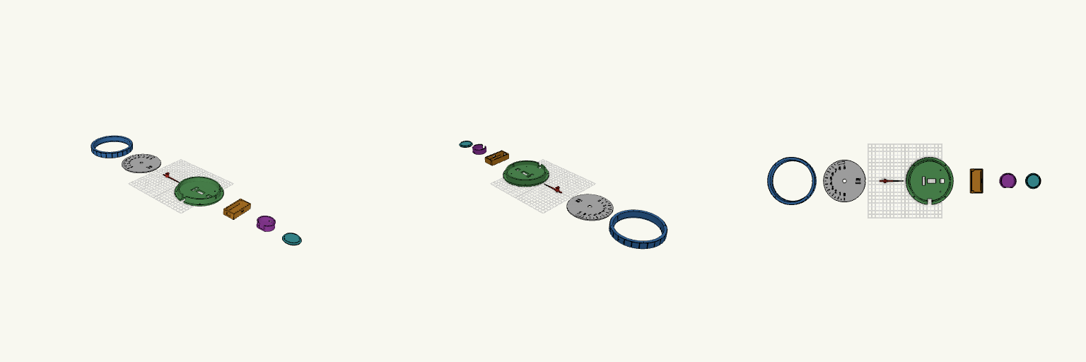
Un tablero de estilo muscle car a escala grande: 127 mm de diámetro exterior, con la esfera estriada, el dial negro de números grandes y una aguja fina de punta afilada que evocan los tacómetros AutoMeter de los tableros deportivos. La escala barre de 0 a 9.000 RPM en 180° —de las 6 a las 12 en sentido horario— y la zona roja arranca en 8.000 RPM. Detrás del dial va un servo SG90, así que la aguja se mueve de verdad, y el conjunto no lleva carcasa trasera. El dial mide 113 mm y deja 109 mm de ventana visible: números, marcas y zona roja escalan con el aro para que la aguja llegue a las marcas. El conjunto se imprime en siete piezas separadas y sin soportes: Aro frontal: 127 mm de diámetro, labio de 2 mm, estrías exteriores y cuatro agujeros para tornillos M3. Lleva una llave de orientación para el dial y dos agujeros piloto a las 12, a ±6 mm del centro, para la luz flash de corte de RPM. Dial: disco de 113 mm con los números 0–9 y los textos «RPM» y «x1000» pasantes de lado a lado —con puentes finos de 0,8 mm que sostienen las islas interiores—, marcas cada 500 RPM y zona roja en relieve. El agujero central es de 10 mm más 0,3 mm de juego de encastre. Aguja: perfil fino de aguja real, con puntero de 50 mm que se angosta desde 1,2 mm hasta unos 0,6 mm en la punta y una cola de contrapeso corta; el cubo central es de 10 mm para dejar el dial despejado. Se monta en el brazo del servo recortado a 12 mm de radio y se fija solo con el tornillo central de 3,2 mm, sin pasador. Soporte servo: placa de 4 mm con ventana para el SG90, dos agujeros piloto para la brida, muesca de llave y ventana de 12 × 12 mm para el cable del servo. Se fija al aro con cuatro tornillos M3 y recibe la caja de ESP32 con dos tornillos M3 desde adelante, con los agujeros a ±29 mm. La ventana del servo mantiene las medidas compactas del SG90. Caja ESP32: pieza aparte de 31 × 65 × 16 mm para una placa de 30 pines de unos 51 × 26 mm, con ranura para el USB, dos rieles internos que sostienen la placa y salida de cable hacia el soporte; se adosa al soporte del servo y queda por detrás. Caja de LEDs: cilindro de 41 mm de diámetro y 14,8 mm de alto, con paredes y fondo de 2 mm y cámara abierta hacia el frente. Va a las 12, con el borde curvado apoyado en el aro, y se fija con dos tornillos M3 horizontales a ±6 mm del centro; la salida del cable de la tira LED está en la pared trasera. Quedan unos 37 mm libres en el interior, suficientes para un LED o un tramo corto de tira. Tapa difusora: disco de 41 mm con solo 1,2 mm de piel, con un anillo guía que entra con 0,3 mm de juego. Es fina para que pase la luz y se imprime con la cara exterior hacia abajo; puede imprimirse en el color del flash —rojo, azul o blanco— en PLA translúcido o natural. Notas de armado y acabado: Los números pasantes dejan pasar la luz de atrás: se puede colocar un filtro de otro color detrás del dial y cambiar el tono de la iluminación. Los puentes se ven como una línea fina en medio de cada número: un puente vertical en el 0 y el 8, uno horizontal en el 4, el 6 y el 9, y otro horizontal sosteniendo la R, la P y los ceros de «RPM x1000». Es lo normal en un estilo stencil. El centro de 10 mm deja paredes de unos 0,9 mm en el cubo de la aguja; conviene imprimir esa zona con 100 % de relleno. Las marcas y la zona roja van en relieve en el mismo archivo que el disco: para cambiar su color hay que pausar la impresión en el cambio de capa. La tira LED no tiene soporte interno: se pega con su adhesivo en la pared interior de la caja de LEDs. Al montar, alineá el brazo del servo en 0° apuntando a las 6 y comprobá la altura del brazo sobre la brida en tu SG90 antes de cerrar el conjunto.
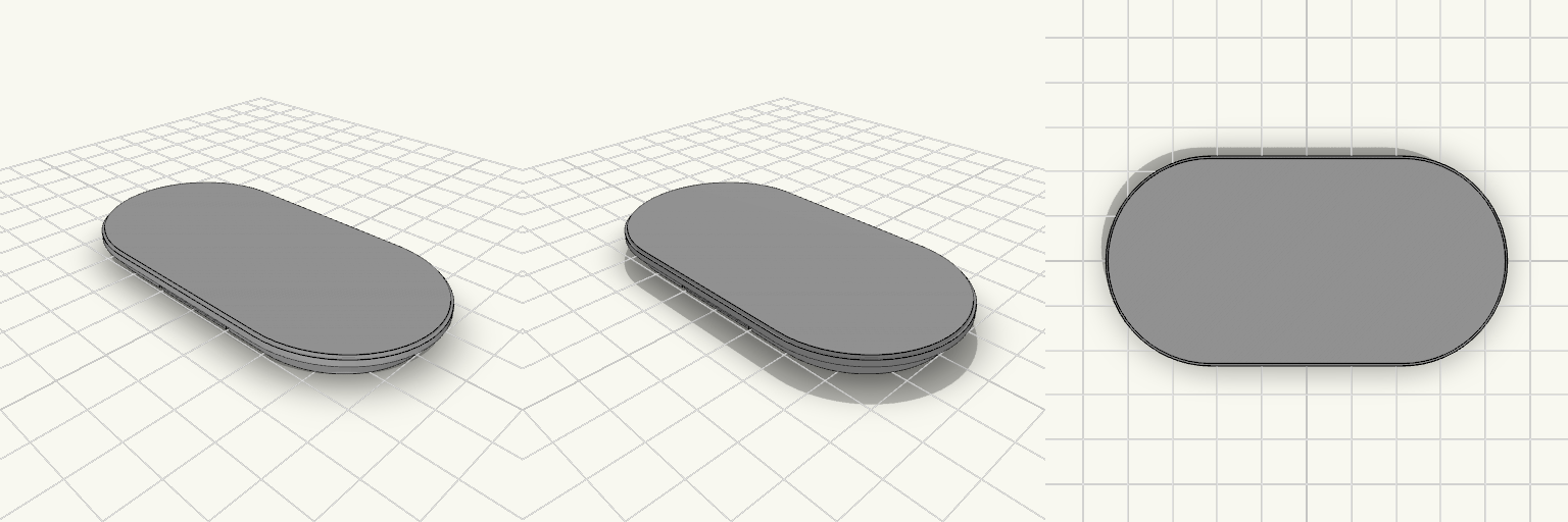
86x45mm Ovaler Karosserie-Blindstopfen mit Snap-Fit-Clips
Geschlossene ovale Abdeckplatte für eine 80 × 39 mm große Öffnung in etwa 1 mm dickem Karosserieblech. Die Kontur ist ein Stadion-Oval, also ein gerades Mittelstück mit vollständig runden Enden. Die Platte wird eingedrückt, die integrierten Snap-Fit-Clips federn zurück und rasten hinter dem Blech ein – ohne Schrauben, Kleber oder separate Befestigungsteile. Die Abdeckung lässt sich wieder entfernen, ohne das Blech zu beschädigen. Das Teil wird als ein Stück gedruckt. Frontplatte: 86 × 45 mm, 2 mm dick, vollständig geschlossen, gerundete Kanten; die 2 mm fallen an der gerundeten Kante etwas dünner aus Einsatz: Außenkante 80 × 39 mm, Endradius 19,5 mm, 4 mm tief, hohle Wand mit 1,6 mm Stärke Innenöffnung: 76,8 × 35,8 mm Flansch: rundum 3 mm breit, an den Längsseiten wie an den Enden; die Clip-Haken liegen vollständig innerhalb der Plattenfläche Clips: zwei Zungen an den Längsseiten oben und unten, je ein 0,7 mm hoher Haken mit Rampen-Anlauf und flacher Fangfläche für 1 mm Blech Clip-Schlitze: 1 mm breit × 6 mm lang durch die Wand der Längsseiten, geben den Zungen Platz zum Federn Passung: Die Außenkante des Einsatzes entspricht exakt 80 × 39 mm, es bleibt kein Spiel – straffer Sitz, vor dem Einbau einen Probedruck einplanen Einbauraum: Die Frontplatte misst 86 × 45 mm; vor dem Einbau prüfen, ob um die Öffnung herum genug Platz für 45 mm Höhe ist Material: PETG oder ASA, mit der Frontseite nach unten drucken Bauteilmaße auf der Druckplatte: 86 × 45 × 6 mm
Need a part that doesn't exist yet?
Start building →