small Bottle Syringe Clip
Created 7 days ago
Remixed 2 times
Description
A custom-sized double ring designed to couple a 14.5 mm syringe to a 31 mm bottle neck.
- Syringe bore: 14.5 mm with an 8 mm front insertion slot
- Bottle bore: 31 mm (snaps on via a 22 mm back slot)
- Clearance: 4 mm bridge spacing
The branding is now recessed 0.6 mm directly into the bottle ring's inner wall, keeping the outer profile completely flush. Check your syringe outer barrel measurement before running this.
Images
More like this
Explore more in Workshop & Tools →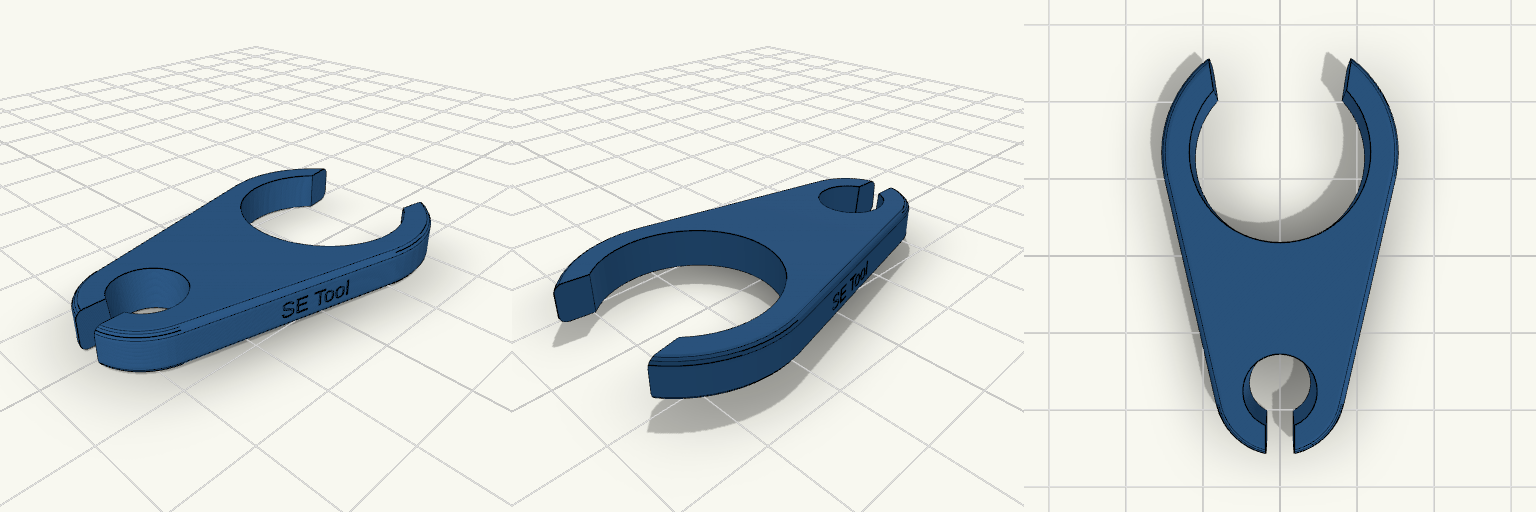
28mm — Tapered Syringe Adapter
A specialized dual-ring tool designed to connect a small tapered syringe (5–6 mm) to a 28 mm bottle neck. Features Bottle Bore: 28 mm with a straight 8 mm snap-on cutout, finished with rounded entry tips. Syringe Bore: Tapered from 5 mm at the bottom to 6 mm at the top, ensuring a snug fit. Bridge: A short 6 mm tapered solid bridge connecting the two mounts smoothly. Branding: "SE Tool" engraved directly onto both side flanks of the tapered bridge.
Console — Custom Electronics Enclosure
This is a comprehensive, dimensionally accurate parametric enclosure designed for DIY electronics. Laid out to securely house a 16×2 character LCD and four tactile push buttons, it uses standard M3 machine screws with captive nut traps for secure and repeatable assembly. The design separates the tactile switch bodies from the actual visible button caps, ensuring a clean and professional appearance. Features Locating Lip: Recessed rabbet ensures the top cover nests tightly and squarely onto the bottom shell. Component-Specific Pockets: 12×12 mm push-button switches are secured from the underside, operated by independent retained caps. Hidden Mounting: The 16×2 LCD is held flush against the top window from the inside via a custom bezel, keeping the surrounding PCB hidden. Directed Ventilation: Cooling slots are restricted to the lower front face, allowing flush wall mounting at the rear. Hardware Needed 4 × M3 × 12 mm machine screws 4 × M3 hex nuts (5.5 mm across flats) 4 × 12×12×7.3 mm tactile switches 1 × 16×2 Character LCD (JHD162A style)
no clip Hilti nuron v3
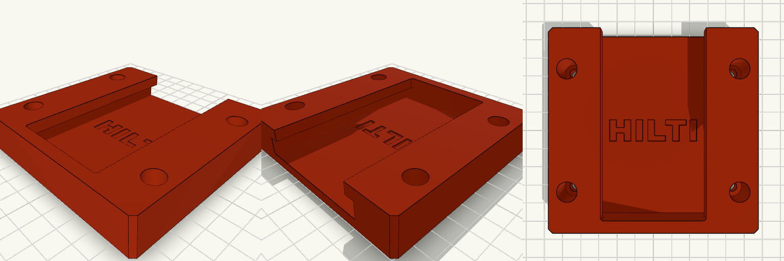
Screws mounted inside the track usually mean the battery casing drags across the screw heads if they don't sit perfectly flush. Moving the mounting holes to the solid outer flanges gets the hardware entirely out of the sliding path and stops the bracket from rocking when you yank a heavy pack out. Width: Pushed out to 94mm to give the screws enough meat to bite into. Clearance: 15mm deep counterbores hide the screw heads in the outer body, leaving a solid 5mm base to clamp against the wall.
SMARTBELT Line Monitor
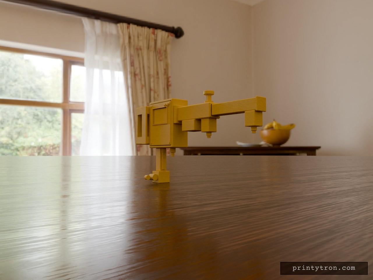
Conveyor belts don't ask before they drift, and a shredded belt stops the whole line. This is a watchdog that mounts rigidly to a steel frame and actually looks at the belt. It features an adjustable heavy-duty C-clamp, a rigid enclosure for an ESP32, a telescoping sensor boom that spans the belt width, and a drop-down arm for proximity speed sensing. The modular design lets you swap out the laser inspection head or IR edge sensors without unbolting the main unit. Assembly & Installation Clearances: Mating faces on the boom base and telescoping arm include a 0.4mm tolerance to ensure a sliding fit straight off the plate. Hardware: Designed for M4 socket head screws on the front cover and M8 bolts for the main structural clamp. Material: Print in PETG or ASA for impact resistance and thermal stability. Support Strategy: The C-clamp and enclosure bodies print upright without supports; the sensor arms require minimal bridging support under the drop-down elements.
Biofloc Monitor Station Enclosure
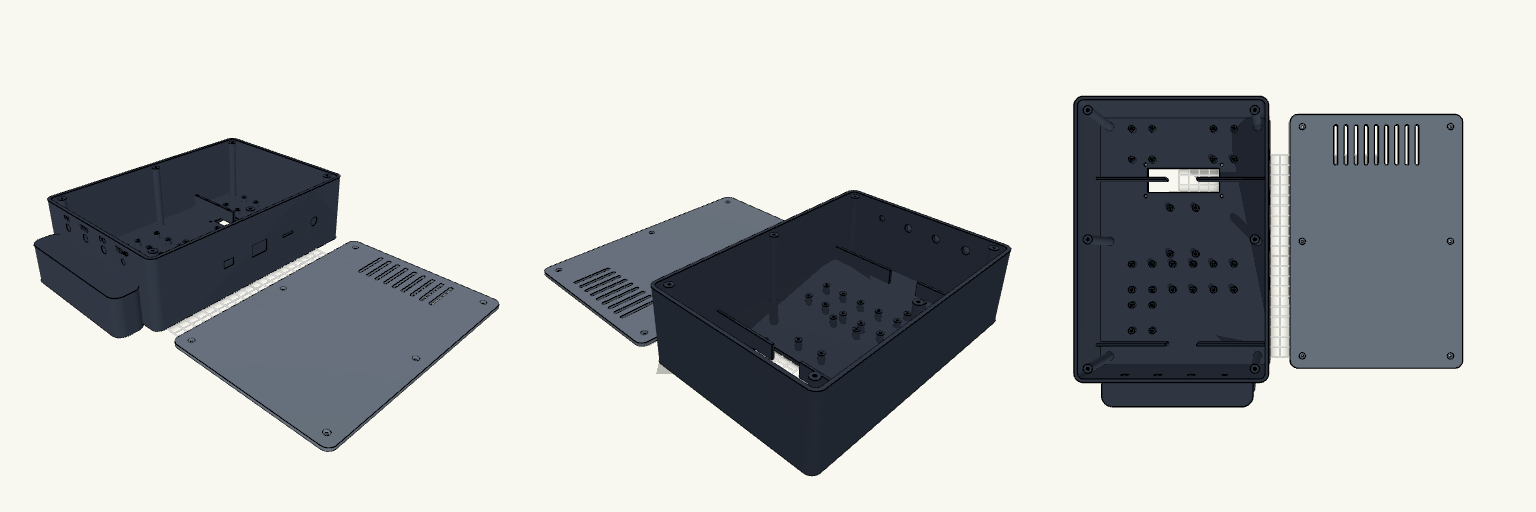
An enclosure is only as good as the snarl of wires it prevents. This is a heavy-duty two-part monitor housing built specifically for FDM printing, designed to group, separate, and anchor a complete suite of biofloc water-quality electronics without turning into a bird's nest inside. The layout isolates the battery compartment at the bottom and keeps the DC buck converters and relay in a ventilated top section, leaving the central deck clear for the ESP32 and an array of sensor interfaces. Internal divider walls double as cable routing channels, forcing the wiring to stay orderly. Core Features Printability: Both halves print completely flat on the build plate (Z=0). The integrated bottom handle is flush with the front face to avoid overhangs. Dimensions: 170 mm width × 250 mm height × 75 mm depth. Hardware Required: 6× M3 screws for the rear cover; additional M3 hardware for the internal standoffs and the 16x2 LCD faceplate mount. Ports: Bottom panel holds 4× sensor ports (3× 8mm, 1× 6mm) with engraved labels. Right panel holds cutouts for 12V DC, an SD card slot, a rocker switch, and USB programming access.
Hilti Nuron Battery Mount
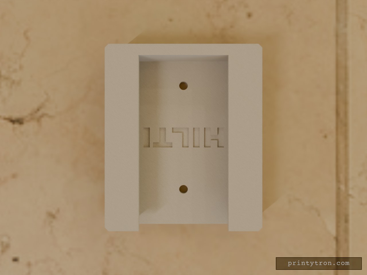
A wall-mounted receiver bracket for Hilti Nuron batteries. Heavy battery packs love to lever short brackets right out of the drywall. This bracket gives them a solid vertical footprint to spread that load, catching the battery's sliding interface on an internal U-channel with a dead stop at the base. Internal Channel: 63mm wide (48mm opening) Clearance: Counter-sunk screw holes keep the hardware below the sliding surface Detail: Features a debossed HILTI logo on the backplate that stays clear of the sliding path