Ángulo — Tira en L de 20 cm
Created 2 days ago
Description
Ángulo — perfil en L de 20 cm de largo, pensado como esquinero, guía o refuerzo de bordes. Dos caras iguales a 90°, de sección sencilla y fácil de imprimir tumbado.
Dimensiones
- Largo: 200 mm
- Ancho de cada cara: 10 mm
- Grosor: 2 mm
Notas de impresión
- Imprimir apoyado sobre una cara, sin soportes.
- Para más rigidez, orientar las capas a lo largo del perfil.
Images
More like this
Explore more in Workshop & Tools →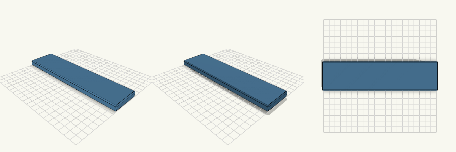
Placa Rectangular 200 x 50 x 10 mm
Placa rectangular maciza de 20 cm x 5 cm x 1 cm, para cuando hace falta una base plana y rígida que no se flexione ni se astille en los bordes. Datos para imprimir Medidas: 200 x 50 x 10 mm Bisel de 1,5 mm en todas las aristas, para que la primera capa no se levante en las esquinas Se imprime tumbada sobre su cara más grande, sin soportes Relleno recomendado: 20 % o más, según la carga
Canal en L con Paredes Altas
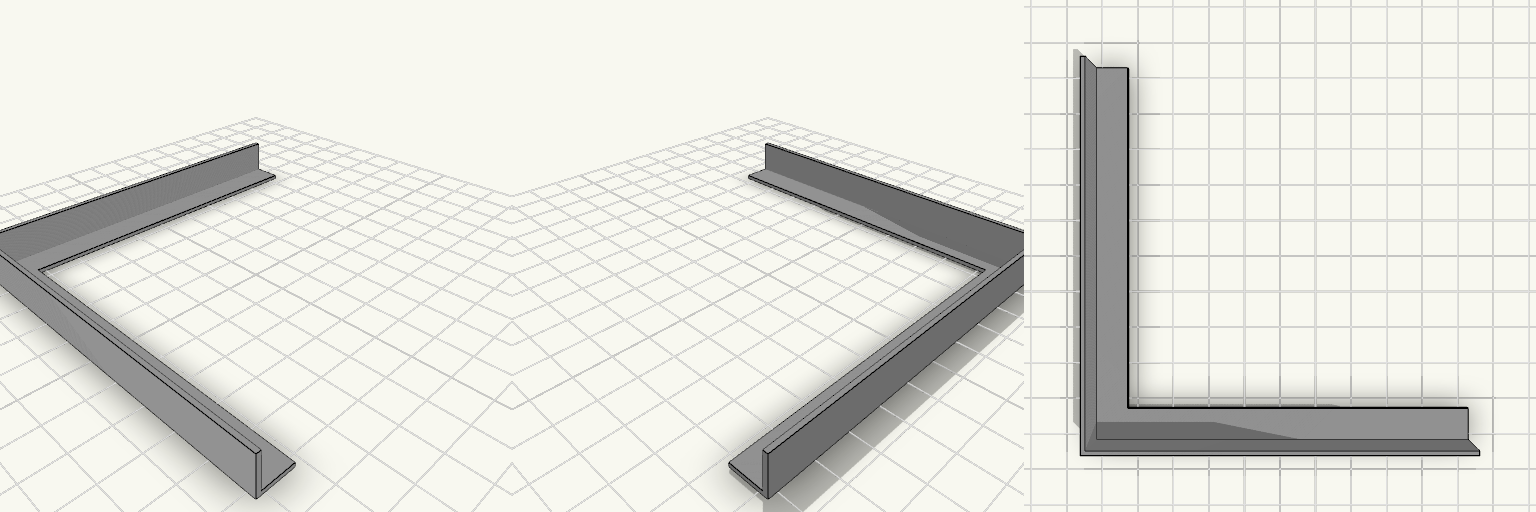
Una tira en L de 200 mm medidos por el centro, con dos brazos en ángulo recto, 10 mm de ancho y base de 1 mm. Las dos paredes exteriores, las más largas, se elevan 10 mm sobre la base y forman un canal de esquina abierto por dentro. Base: 1 mm de grosor Paredes exteriores: 1,2 mm de espesor, 10 mm por encima de la base Bordes interiores (más cortos): sin pared Altura total: 11 mm
30x30x8mm Interposer Plate, 1/4-20 Nut Pocket
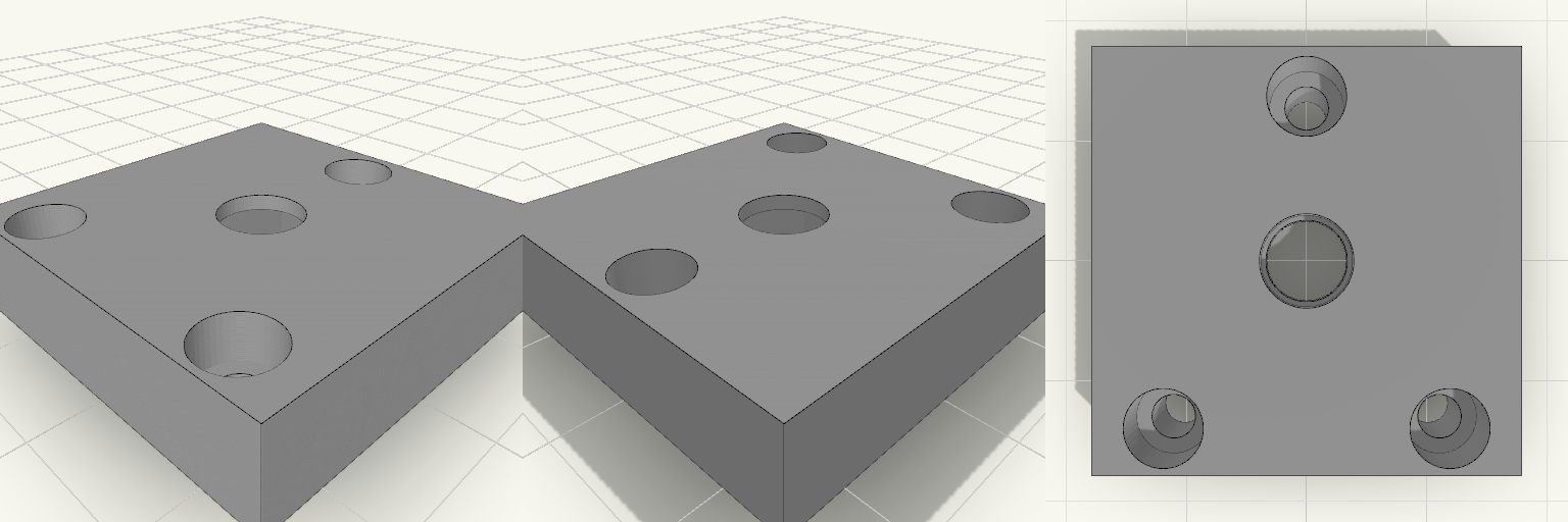
Square-edged 30x30x8 mm interposer plate with a central 6.6 mm hole for a 1/4-20 stud. A hex pocket for a 1/4-20 nut is enclosed inside the plate and is designed for a mid-print pause: the nut is inserted when the print reaches the top of the pocket, and the remaining layers bridge over it. Plate: 30 x 30 x 8 mm, square edges Center hole: 6.6 mm through, for a 1/4-20 stud Nut pocket: 13.2 mm across corners (about 11.4 mm across flats), 5.8 mm deep, from Z 1.0 to 6.8 mm Pause height: Z = 6.8 mm, then resume to print a 1.2 mm cover Screw holes: three 3.3 mm holes with 5.6 mm counterbores from the top face, 3.5 mm deep Triangle pattern: apex 3.5 mm from the back edge, two front holes 20 mm apart Nut size assumed: standard 7/16 in across flats, 7/32 in thick
Tapa cuadrada con agujeros mixtos
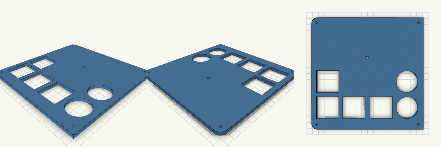
Tapa de 180×180×5 mm con dos lados redondeados a la izquierda (radio 10 mm), cuatro agujeros M3 en las esquinas y un agujero de 5 mm. Dos agujeros redondos de 35 mm a la derecha y cuatro cuadrados de 36 mm a la izquierda, en la zona inferior. Ideas para remezclar Diámetro de los redondos (35 mm): súbelo o bájalo según la pieza que deba pasar; la pared entre ellos es de 7 mm. Lado cuadrado (36 mm): ajústalo por separado; los centros están a 42 mm. Radio de las esquinas (10 mm): 5 mm para una curva más suave. Agujero de 5 mm: está a 25,5 mm sobre el centro; muévelo para un pasacables o un pulsador. Combina con: una base o caja de 180 mm usando los M3 de las esquinas (3,4 mm, a 8 mm del borde).
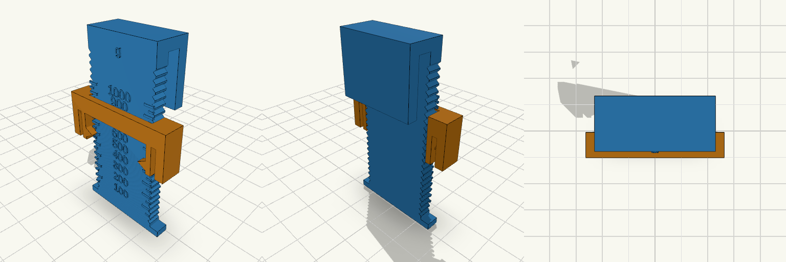
SpoolScope — Filament Remaining Gauge
SpoolScope is a two-part gauge for estimating how much filament remains on a standard spool, made for spools that sit out of easy view in an AMS or on a shelf. The rail hooks over the flange rim; the sliding block rides on it with light detents, so you can push it down until it touches the filament, lift the gauge away and read the result. Raised ticks and numbers plus an unambiguous arrow on the block make the measurement clear without needing line-of-sight while the gauge is in place. Features Two printed parts: a rail with a rim hook, and a detented sliding block. Gram scale from 0 to 1000 g, with ticks every 50 g and numbers every 100 g. Ticks follow filament geometry rather than an even spacing: closer together near full, wider apart near empty. Arrows on the block tip directly toward the scale, and the detents hold the reading after the gauge is lifted off. Hook gap of 4 mm, sized to clear flanges from 2.8 mm to 3.6 mm thick. Dimensions Flange diameter: 200 mm. Hub outer diameter: 95 mm (from a measured Polymaker spool). Full-roll diameter: 170 mm (estimated from a 1 kg PLA roll on a 95 mm hub and a 65.6 mm spool width). Hook gap: 4 mm. Fitting and calibration Sized around Polymaker and Inland 1 kg spools; other brands are worth checking against the hub and flange figures above. The scale can be shifted by a single fixed offset if a first print reads consistently high or low, so a weight check against a known spool is worth doing before trusting the numbers. If the error differs between a full and an empty spool, the hub and full-roll values are the ones to correct. Print notes Both parts are laid out flat on the print plate. The block contacts the filament at its outer edges rather than at the centre, so a reading can sit slightly high; a weight check against a known spool is the best way to confirm the scale.
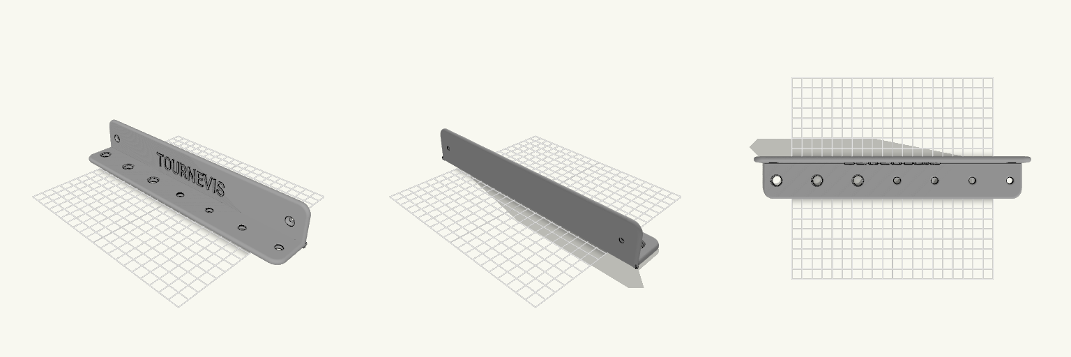
Support mural tournevis 255 × 40 × 40 mm
Support mural pour tournevis : plaque verticale de 255 × 40 mm et tablette horizontale de 255 × 40 mm, épaisseur 5 mm. Trous de la tablette, de gauche à droite : 10, 10, 10, 7, 7, 7, 7 mm, bords arrondis. Deux trous de vis fraisés dans la plaque. Texte « TOURNEVIS » en relief de 1,5 mm. Coins extérieurs arrondis à 10 mm ; les deux coins à la jonction plaque/tablette sont droits. À vérifier avant impression : la longueur de 255 mm doit tenir sur votre plateau. Ne convient pas aux tournevis dont la tige dépasse 10 mm.