Articulated Sim Racing Keyboard Arm
Created 1 months ago
Remixed once
Description
This modular arm mounts a Logitech K235 wireless keyboard to a tubular sim racing chassis, allowing you to swing the keyboard into your lap for typing and fold it away while driving.
The mechanism relies on structural box-section arm segments and heavy-duty M6 bolted joints to prevent sagging and resist vibration. A split-clamp base mounts to the frame without drilling, and the central keyboard tray uses recessed neodymium magnets to keep the keyboard anchored during intense force-feedback moments.
Hardware Required
- Cockpit Mount: 2× M5x50mm bolts & hex nuts.
- Articulated Pivots: 3× M6x40mm bolts, washers, & nylon lock nuts.
- Keyboard Retention: 4× 10x3mm circular neodymium magnets (press-fit or glued into the tray).
Printing Advice
- Material: PETG, ABS, or ASA for rigidity and impact resistance.
- Orientation: Print all parts flat on the bed as laid out. The tray is designed compactly to fit comfortably on a 220x220mm print surface.
- Settings: Use a minimum of 4 perimeters/walls and 30%+ gyroid infill for the arm segments to ensure lateral strength.
Images
More like this
Explore more in Automotive, RC & Hobby →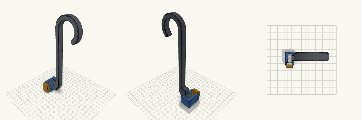
Gancho de Garrafa com Braçadeira Snap
Gancho de garrafa de treino em J, 200 mm, com braçadeira bipartida na base: corpo fixo ligado à haste e tampa separada que fecha por encaixe de pressão ao redor da alça de 12 × 24 mm. Pontos de remix Snap-fit: ganchos flexíveis de 8 mm de comprimento, 1,8 mm de espessura e ressalto de 0,6 mm (armlen, armt, ridge). Entrada em rampa, retenção reta. Folga: 0,2 mm entre tampa e corpo (gap). Trava extra: furo M3 em gota atravessando tampa e corpo, com porca sextavada embutida no lado +X. Paredes: wallx (6,4 mm) e wallf (7,5 mm) definem o tamanho externo; reduza se o furo M3 for dispensado. Haste e gancho: inalterados, seção 10 × 14 mm, bojo de 40 mm, boca de 34 mm. Combina com: parafuso M3 e porca M3 (opcionais); imprima corpo e tampa separados em PETG ou PLA.
Wall-Mounted Jack Stand Hanger small support
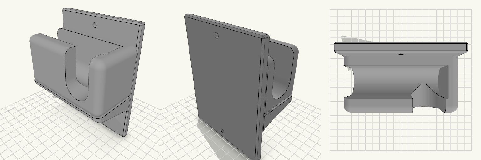
A wall-mounted holder that keeps a 3-ton jack stand off the garage floor and within reach. The flat vertical back plate carries a U-shaped cradle in the centre, open at the top so the stand's bar drops in and lifts out. The cradle is open through the middle and closed by a 10 mm wall at each end, so the bar cannot slide sideways off the holder. The front wall of the cradle is a 13 mm lip that catches the bar and stops it sliding forward. The cradle walls are rounded with a 7 mm radius on every edge except the one against the back plate, and the inner floor is a rounded half-cylinder trough running the length of the opening, 28 mm across to match the seat, so a round bar or handle lies in it without rocking. The holder prints as one piece with no assembly, and it is sized for a 3-ton jack stand and its handle. A compact gusset supports the cradle underneath and runs the full 100 mm width of the cradle, so the end walls sit flush on it instead of overhanging. Its corners carry the same 7 mm radius as the cradle, so the walls run down into it with no ledge. The underside is an S-curve: it leaves the back plate 39 mm up, sweeps out and finishes running straight up the back of the front lip, meeting both surfaces tangentially so there is no crease where it joins. Keep it around this size — trimming it much further leaves the cradle with little support against the weight of a loaded stand. The jack handle hangs from two cuts, so it drops in from above rather than being threaded in from the front. A 28 mm slit in the front wall, open at the top, sits 24 mm right of centre and stays clear of the right edge, which runs fully to the front and stands even with the left wall. Opposite it, the left end wall carries a matching 28 mm notch, open at the top. Both cuts share the cradle trough's floor depth, with their centreline at 80 mm up and their floors bottoming out at 66 mm. The slit floor starts at the trough centreline with a rounded blend where the two meet, so the handle slides from the trough into the slit and notch without a step and hangs clear below. The cradle walls stand 55 mm tall, topping out at 110 mm up, which leaves about 16 mm of wall above a 28 mm handle resting at 80 mm. Overall: 100 mm wide, 130 mm tall, 57 mm deep Cradle: U-shaped, 28 mm bar seat, open top, open through the middle, 10 mm end wall each side, rounded floor trough Cradle walls: 55 mm tall, tops at 110 mm, rounded at 7 mm Bar opening: about 80 mm between end walls Front lip: 13 mm thick Handle slit: 28 mm, open at the top, set 24 mm right of centre in the front wall, floor blended into the trough Left end wall: matching 28 mm notch, open at the top, for the other side of the handle Floor height: slit, notch and trough all bottom out at 66 mm Gusset: full cradle width, 7 mm rounded corners, S-curve underside tangent to the back plate and the front lip, meeting the plate 39 mm up Mounting: one countersunk screw hole above the cradle and one below; use 5 mm or larger screws into a stud or suitable anchor Material: grey PETG suits the load and garage conditions; edges are chamfered Check that the stand's bar fits the 28 mm seat and the 80 mm opening, and that the handle fits the 28 mm slit and notch before printing. If the bar or handle is larger, widen the seat or the cuts to match.
Ladeo — Prensa Lateral Servoaccionada para G-Seat
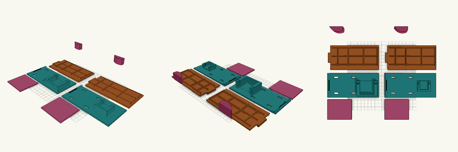
Ladeo es una prensa lateral servoaccionada para un G-Seat de simulador de carreras. La versión actual incluye dos montajes completos lado a lado: uno para Futaba S3003 y una copia para SG90, con las mismas placas, bisagra y leva, y una cuna distinta para cada servo. Se entrega en despiece, con cada pieza apoyada en la cama, para imprimir y montar como un apoyo lateral acolchado que cierra contra el cuerpo, al estilo del sujetariñones de una silla. La bisagra va montada en el extremo corto de la placa. Piezas del despiece Placa fija con bisagra: lleva la bisagra de pasador de 2 mm en el extremo corto, las 4 ranuras de fijación (X 25 y 75, Y 12 y 58) y la cuna del servo. Hay dos copias lado a lado; el conjunto de placas fijas ocupa unos 313 × 70 mm en la cama. Placa móvil con refuerzos: placa de 3 mm con venas de 2 mm de ancho por 4 mm de alto: 3 longitudinales y 4 transversales. Hay dos copias. En el despiece va plana; la inclinación de reposo no está aplicada. Acolchado: pieza aparte de 3 mm de espesor, una por montaje. Leva: perfil cilíndrico recortado; se imprime acostada sobre su cara lateral. No trae cubo ni agujero para el eje o la cruceta del servo. Soportes de servo Cunas: las dos comparten paredes laterales con 0,3 mm de holgura, tope trasero, base elevada para dejar el eje a Z 13, muesca para las orejas y dos agujeros guía de 2,5 mm para tornillos autorroscantes. Futaba S3003: cuerpo de 40,4 × 19,8 × 36,5 mm, orejas de 55,5 mm y agujeros a 49,5 mm. SG90: cuerpo de 22,7 × 12,2 × 22,7 mm, orejas de 32,5 mm y agujeros a 27,5 mm. En esta copia el cuerpo queda desplazado 5,5 mm del eje, frente a 10,2 mm en el Futaba; la posición del eje de la leva no cambia. Las alturas de las orejas son estimadas: prueba el servo real en la cuna antes de imprimir. Mecanismo La bisagra es fina: cilindro de 5,5 mm y pasador de 2 mm, con el eje en el extremo corto de la placa, a X≈5, a lo largo de Y y a Z≈4. La placa fija lleva dos nudillos (Y 0–20 y 50–70) y la placa móvil uno entre ellos (Y 21–49), con 0,3 mm de holgura. La placa móvil se abre levantando el extremo opuesto a la bisagra, hacia X≈148; el servo y la leva quedan cerca de ese extremo libre. La leva es un cilindro de 50 mm con la parte posterior atenuada y un ancho de 18 mm en Y; empuja por debajo de la placa móvil, cerca de la zona opuesta a la bisagra. Gira de 0° a 90°, en reposo queda girada 43° hacia abajo, y a 90° el punto más alto sube unos 30 mm sobre el reposo, no los 40 mm de una carrera ideal. Con la bisagra en el extremo corto, la leva empuja cerca del extremo libre, la zona que más sube, así que la apertura real puede variar; conviene comprobar que la placa abierta no roce la cuna del servo. El contacto es aproximado porque la punta arrastra sobre la placa; un rodillo o una ranura en la placa móvil daría un contacto más preciso. Montaje y ajuste Para que apriete el cuerpo, la placa móvil debe quedar del lado de la persona. No lleva resorte de retorno: hace falta una banda elástica entre las placas o que el propio cuerpo devuelva la placa. No tiene topes ni protección contra sobrepresión; el límite lo marcan la forma de la leva y el contacto con la placa. Verifica las 4 ranuras contra el sujetariñones real, la altura del eje del servo y las holguras de la bisagra antes de imprimir. Revisa que el pasador de 2 mm salga limpio, que la placa móvil gire sin forzar, que la placa abierta no roce la cuna y que la leva pase libre y quede dentro de la placa.
Pinch-Feed Drive Roller, Print-Ready
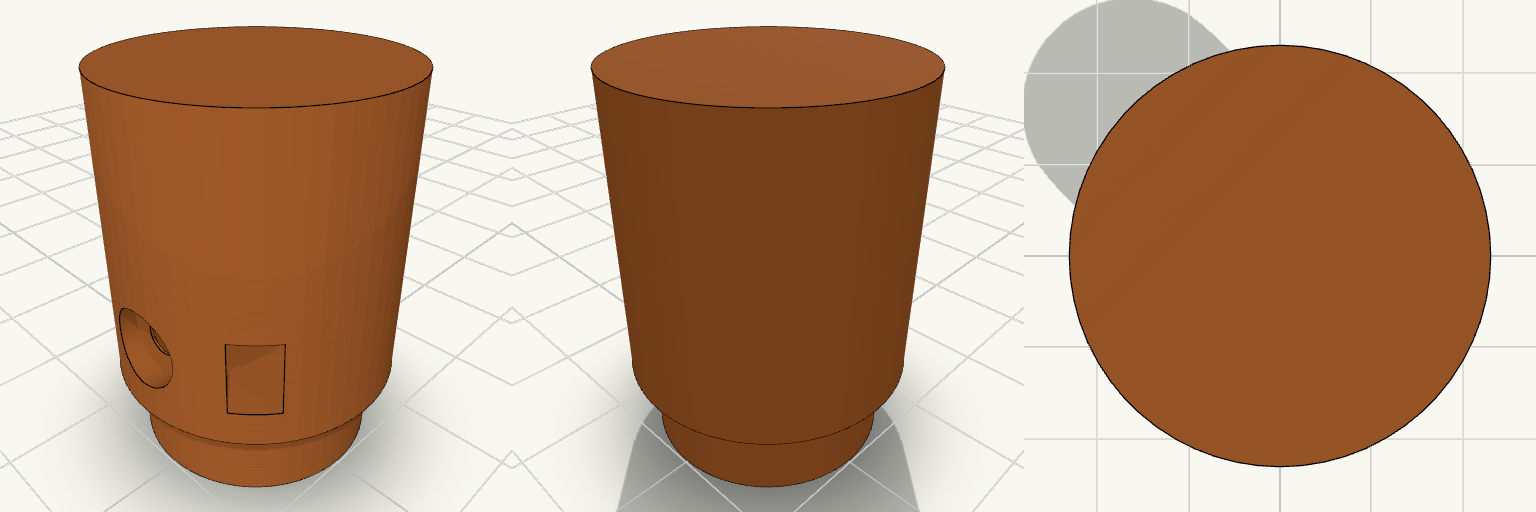
A knurl-free drive wheel for a pinch-feed wire feeder, built like a small industrial pulley: a 24 mm roller with a hub on one side and a blind D-bore that slips over a 5 mm D-shaft. The model is just the roller, standing on its hub and ready to slice. Design notes Blind D-bore, open on the hub face and closed by a wall on the far end, so the closed end shows which side stays out. M3 grub screw hole with a trapped hex nut that slides in through a slot open to the rim. Counterbored screw recess 2 mm deep, so a headed M3 screw sits below the surface and a nylon or TPU sleeve goes on smooth. Hub spaces the roller off the motor face so the two do not rub. Printing Stands on the hub with the bore opening onto the bed, so there is no bridging inside the bore and no supports are needed. Printing upright keeps the roller round. Suggested: PETG, ASA or nylon, 3 or more walls, 25–30% infill.
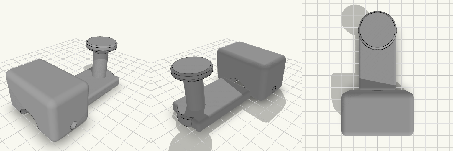
Mountain Bike Wagon Hitch with Capped Post
What it's for A hitch that lets a mountain bike pull a wagon by its C-shaped handle. The bike side is a clamp block that grips the frame tube with a pinch bolt; a flat arm carries that back to an upright post. The post ends in a 12 mm neck with a flared cap on top, so the wagon's C-handle drops over it and cannot slide off while you ride. Clamp block with a 22 mm bore and a single pinch bolt — check this bore against your actual seat stay or axle tube before printing, and scale the clamp if your tube differs Flat arm sets the post behind the clamp, clear of the frame Capped neck holds the handle on but still lifts off when you want to unhitch Dimensions Overall footprint on the plate: 50 × 83 × 38 mm Clamp bore: 22 mm Post neck: 12 mm diameter, about 22 mm tall, with a flared cap above it Print notes Print the part as oriented on the plate so the clamp bore and the neck stay round and the arm keeps its strength across the layer lines. A tough filament such as PETG or ABS/ASA suits a part that takes trail vibration and towing loads better than plain PLA. Remix ideas Resize the clamp bore for thinner or thicker frame tubes, or split the clamp into a two-bolt version for rougher trails Lengthen the arm to move the post further back for wider cargo or tighter frame clearance Swap the capped neck for a ball or pin joint if you want the wagon handle to pivot more freely
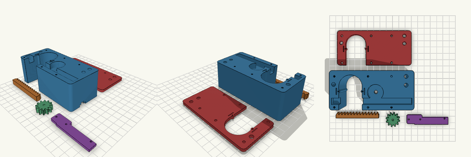
final version 25 mm Paddle Shaft
Motorised rack-and-pinion U-holder for a 30 mm paddle shaft, with hollow flexing snap detents on the slot walls. Fit Host: 30 mm round paddle shaft in a 32 mm slot; N20 gear motor, 12 × 10 mm body, 3 mm shaft. Detents: each slot wall has a hollow bump (1 mm radius through-hole) on a flex finger with a relief slit. The cover plate carries the same features. Not for: shafts other than about 30 mm, or motors with a different body size. Check before printing Measure the N20 body length including gearbox and terminals; the motor length is a parameter. Detent stiffness depends on the bump height and the hole radius. Adjust them for your filament. Parts Housing, sliding rack, pinion, motor retainer and cable cover (one piece), guide cover plate.