Einhell Charger Wall Mount definitivo
Created today
Description
Piastra da parete dedicata ai caricabatterie Einhell Power X-Change.
L'interasse standard tra i fori superiori è di 50 mm, con il foro inferiore centrato a 94 mm verso il basso, tipico del modello da 3.0A. I pioli sono rinforzati con una base conica per sopportare lo scorrimento laterale senza spezzarsi lungo i layer della stampa.
- Fori viti: Calibrati per viti a testa conica stretta.
- Fissaggio: Tre punti d'ancoraggio centrali.
- Pioli: Testa svasata per facilitare l'inserimento.
Images
More like this
Explore more in Workshop & Tools →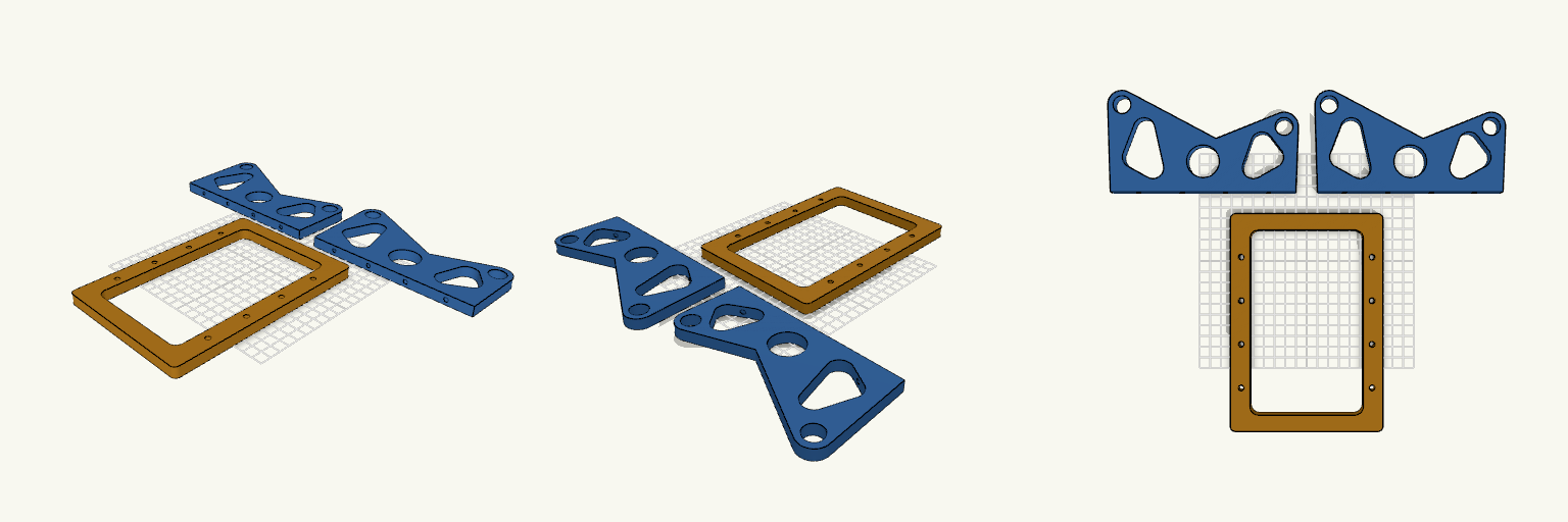
Wide-Stance Filament Bracket Set
A sturdy, flat-packed filament spool holder with an open frame base and dual arching uprights. Designed for standard 16mm rods or dowels, this is laid out flat for maximum printing strength along the layer lines. Remix Hooks Rod Diameter: Currently tuned to 16.5mm to comfortably clear 16mm rods. Upright Spacing: The upright arches span 150mm between the 80mm and 60mm heights. Hardware: Sized for 9mm diameter screw heads to sink flush into the 10mm thick base, clamping down into the uprights.
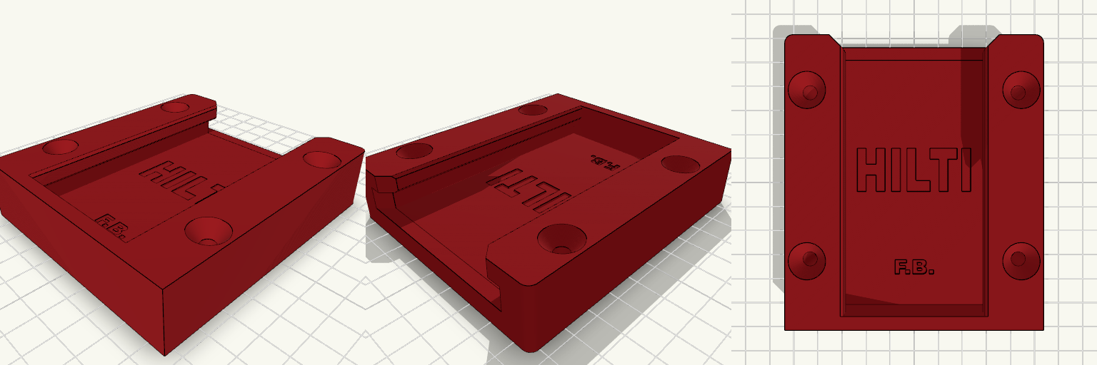
Hilti Nuron Battery Bracket v3
What it's for A heavy-duty, wall-mounted slide bracket engineered specifically for Hilti Nuron battery packs. Designed to mount vertically, it features precision-cut clearance channels and flared 45-degree entry ramps for blind sliding, backed by a solid stop block to prevent bottoming out. Four reinforced, deep-countersunk screw channels ensure the mount stays locked to the wall regardless of the battery weight. Dimensions Overall footprint: 107 mm length × ~93 mm width × 23.5 mm depth. Internal track: 61.5 mm outer track width, 51.5 mm inner neck clearance. Mounting: 4× countersunk screw holes (5.5 mm shaft, 13.5 mm head, 5 mm deep sink). Print notes Recommend rigid, high-strength materials like PETG or ABS to handle the repeated friction and weight of the Nuron packs. Print face up with the flat back resting completely against the bed. Clearances are set to exact measurements, so a well-tuned printer is necessary to keep the slide rails from binding.
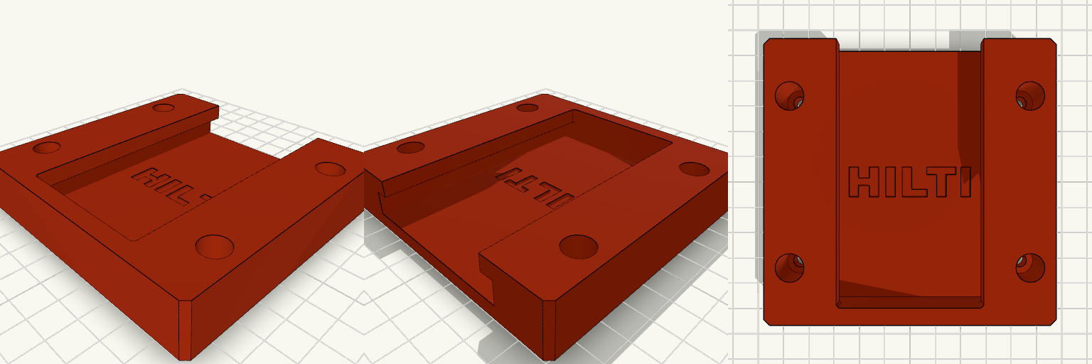
no clip Hilti nuron v3
Screws mounted inside the track usually mean the battery casing drags across the screw heads if they don't sit perfectly flush. Moving the mounting holes to the solid outer flanges gets the hardware entirely out of the sliding path and stops the bracket from rocking when you yank a heavy pack out. Width: Pushed out to 94mm to give the screws enough meat to bite into. Clearance: 15mm deep counterbores hide the screw heads in the outer body, leaving a solid 5mm base to clamp against the wall.
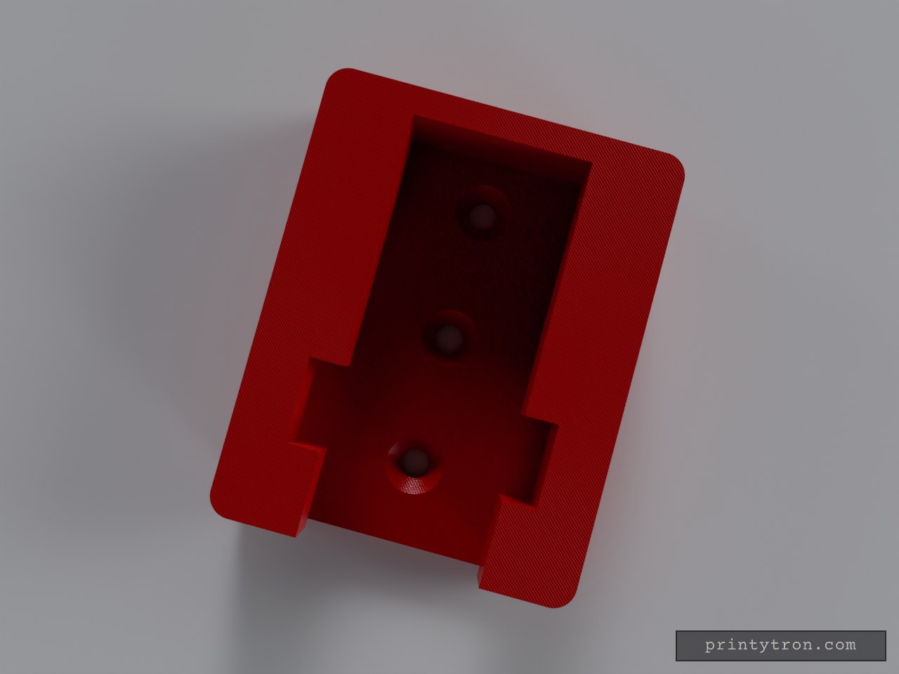
M18 Battery Mount
A wall- or bench-mountable receiver designed to hold a Milwaukee M18 battery. The block features an internal track that matches the battery's rails, allowing it to slide into place securely. Interface: Female slide-track (receives the battery) Mounting: 4x countersunk holes sized for #8 or #10 screws Orientation: Includes an internal stop at the back so the battery rests securely when mounted vertically
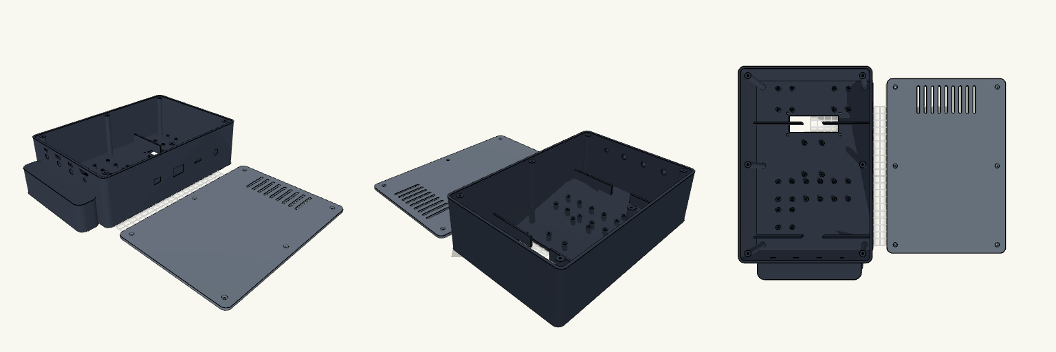
Biofloc Monitor Station Enclosure
An enclosure is only as good as the snarl of wires it prevents. This is a heavy-duty two-part monitor housing built specifically for FDM printing, designed to group, separate, and anchor a complete suite of biofloc water-quality electronics without turning into a bird's nest inside. The layout isolates the battery compartment at the bottom and keeps the DC buck converters and relay in a ventilated top section, leaving the central deck clear for the ESP32 and an array of sensor interfaces. Internal divider walls double as cable routing channels, forcing the wiring to stay orderly. Core Features Printability: Both halves print completely flat on the build plate (Z=0). The integrated bottom handle is flush with the front face to avoid overhangs. Dimensions: 170 mm width × 250 mm height × 75 mm depth. Hardware Required: 6× M3 screws for the rear cover; additional M3 hardware for the internal standoffs and the 16x2 LCD faceplate mount. Ports: Bottom panel holds 4× sensor ports (3× 8mm, 1× 6mm) with engraved labels. Right panel holds cutouts for 12V DC, an SD card slot, a rocker switch, and USB programming access.
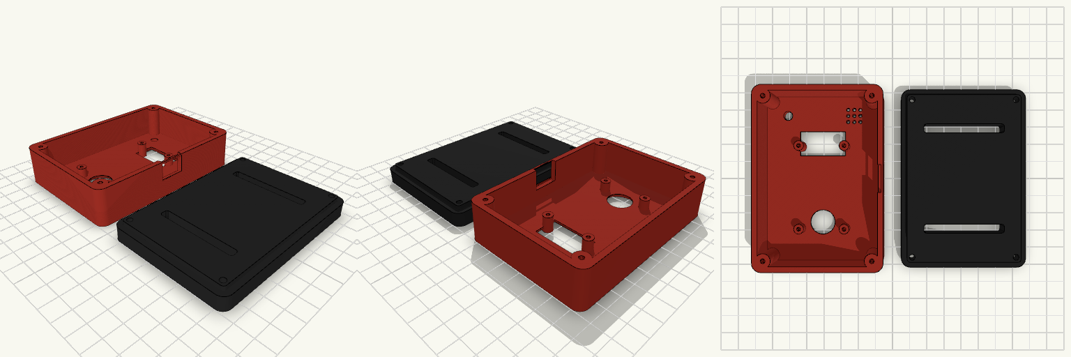
ESP32 SafeCore Controller Enclosure
A dedicated heavy-duty housing for the SafeCore monitor, built entirely around the 30-pin ESP32 dev board footprint and a standard 0.96-inch OLED screen. The two-piece shell is engineered for exact fitment, using a registration lip to keep the halves aligned and transferring shear stress away from the fasteners. Mating Specifications Controller: standard 30-pin ESP32 dev board (25.5 × 47 mm mounting footprint). M2.5 thread-forming posts. Display: 0.96-inch OLED (I2C), sits behind a 26 × 14 mm sloped FDM-safe bezel. Hardware: Four M3 countersunk screws for the rear panel. Indicators: Top-left 5 mm warning LED port and top-right buzzer grille. Mounting: Twin 45 × 5 mm rear slots for standard nylon or Velcro belt straps.