Funda Galaxy A20e pablo
Created 1 months ago
Description
Funda rígida diseñada específicamente para las dimensiones del Samsung Galaxy A20e (147,4 × 69,5 × 8,3 mm), incorporando márgenes de tolerancia estructurales para facilitar la inserción del dispositivo. La cara trasera presenta el nombre "Pablo" integrado en relieve volumétrico sólido, utilizando la fuente seleccionada para maximizar la resistencia de las letras.
- Material recomendado: PLA, PETG o TPU (dependiendo de la flexibilidad deseada).
- Relieve de texto: 1,5 mm, extruido hacia el exterior.
- Tolerancias: +0,6 mm en ejes X e Y para un acople por fricción sin forzar la estructura.
- Perforaciones: Cámara principal dual, lector de huellas dactilares trasero, botonera lateral completa y acceso inferior (USB-C/Audio/Altavoz).
Images
More like this
Explore more in Desk & Tech →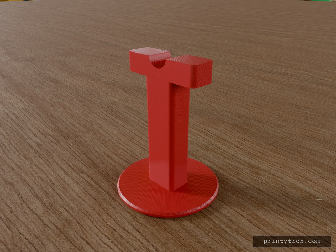
Bedside Reading Glasses Stand, 18mm Bridge
A freestanding bedside stand that holds a pair of reading glasses by the bridge, so they rest off the nightstand and out of the bedding. The top of the column is shaped into a rounded nose-bridge saddle, 18 mm wide at the rim, matching the typical lens-to-lens distance on standard reading glasses. A 90 mm round base keeps the stand upright. Specs Overall size: 90 mm diameter x 116 mm tall Base: 90 mm diameter, 5 mm thick, chamfered edge Column: 30 x 22 mm cross-section, rounded vertical corners Top block: 70 x 22 mm, 16 mm tall Saddle: round dip, 18 mm wide at the rim, 8 mm deep Single-piece body, prints base-down with no supports needed Suggested material: PLA or PETG; 3 or more perimeters for a stiff column Use Place on a nightstand and hang the glasses by the bridge across the saddle. The wide top block and 90 mm base keep the stand stable under light glasses.
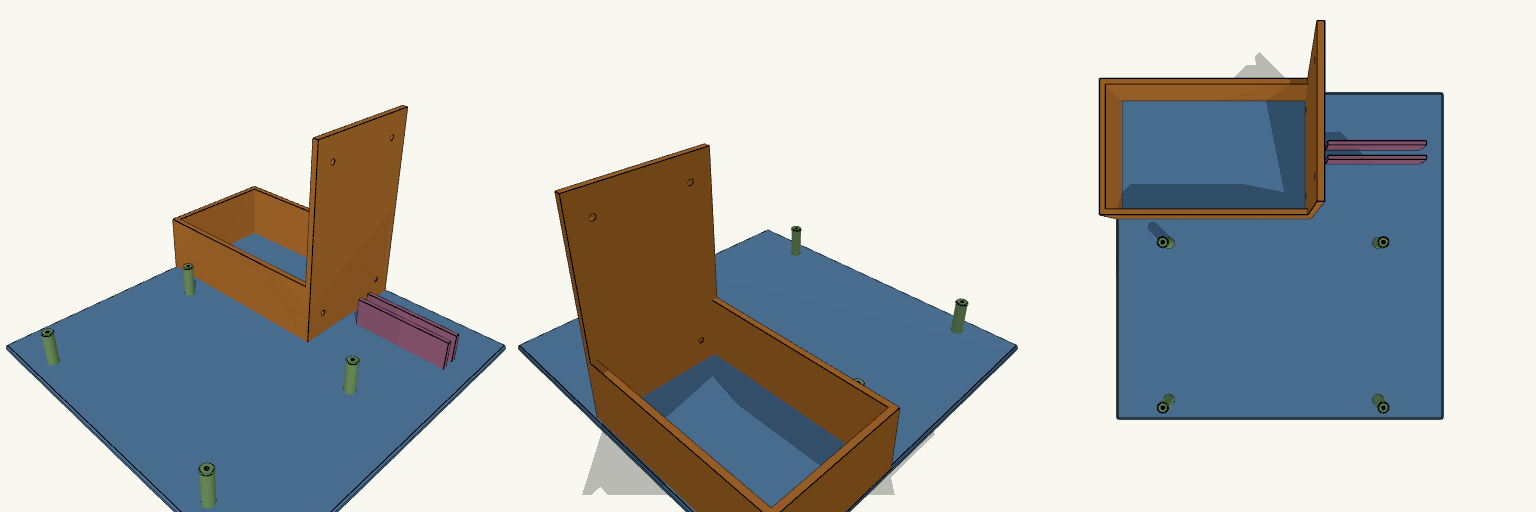
Open-Frame PC Test Bench for 250 mm Beds
An open-frame PC test bench should stop the PSU, motherboard and SSD from shifting while you build; this one does it on a single 250 × 250 mm plate that fits a 256 × 256 mm printer bed. The base is 4 mm thick, and the whole bench prints as one piece in PLA. Fit and print numbers Base plate: 250 × 250 × 4 mm; one-piece print. PSU socket: 140.4 × 86.4 mm pocket with 4 mm walls on three sides; rear bracket 150 mm tall with four ATX screw holes at 64 × 114 mm spacing, 4.2 mm diameter. Motherboard: four 25 mm-high standoffs with 2.8 mm pilot holes for M3, spaced 160 × 120 mm. This is not the standard mATX hole pattern, so check it against your board first; a full mATX board will overhang the plate. SSD: 72 mm-long slot with two 3 mm walls, 22 mm high, holds a 7 mm-thick 2.5-inch drive on its edge. The layout is a compromise for a 250 mm bed: the PSU and board both need room, so the standoff spacing is fixed at 160 × 120 mm rather than a true mATX pattern. Print it in PLA if you want the base stiff without extra parts.
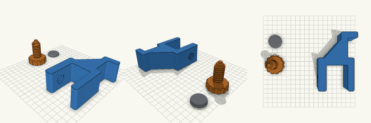
Perch — Clamp-On Headphone Holder
Perch is a three-piece desk-edge headphone holder: a main body with hook and clamp jaws, a separate threaded adjustment screw with a large scalloped knob, and a loose pressure pad. Nothing is joined or printed in place, so the parts are laid out separately and assembled by hand after printing. Features Clamp range of 15–35 mm, suited to a 20 mm desk Internal thread in the lower jaw with 0.4 mm radial clearance for the 18 mm, 4 mm-pitch screw 40 mm knob with scalloped grip Pad snaps onto an 8 mm peg at the screw tip and spins freely Reinforced hook with gusset and rounded lip Print notes Body on its side, screw knob-down, pad flat PLA, 0.4 mm nozzle, 0.20 mm layers, 4 walls No supports expected Assembly Thread the screw up through the lower jaw from below, then press the pad onto the peg. Set the source's mode value to 1, 2 or 3 to export each part individually.
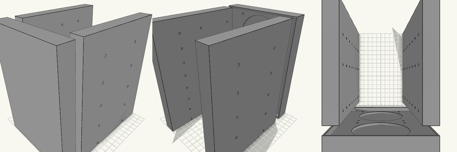
Octobay — 5.25" to 3.5" Drive Cage
Octobay turns a five-bay stack of half-height 5.25" slots into room for eight 3.5" drives, and adds a 25 mm front cage that carries two 92 mm fans. The outer side faces take M3 heat-set inserts, so the whole cage screws into the case's 5.25" rails instead of resting on them. Everything is one printed part: the drive stack, the side mounting blocks and the fan cage print as a single body. Because the fans close off the front, drives now load from the back. The fan cavity behind the grille is hollow, so air still passes through to the drive stack. Dimensions Overall: 145 mm wide × 197.5 mm deep × 205.5 mm tall Fits: five half-height 5.25" bays Holds: eight 3.5" drives, stacked vertically Drive channel: 102.6 mm wide — 1 mm of play around a 101.6 mm drive Mounting 20 insert holes, 10 per side, for M3 heat-set inserts — 4.2 mm across and 6 mm deep Two insert holes per bay, at 41.3 and 117.5 mm from the front, 6.35 mm above each bay floor Solid blocks sit behind each hole to give the inserts something to bite into Three M3 screw holes per side per drive, at 14, 76.6 and 117.6 mm from the front Cross ribs sit clear of the screw holes so a screwdriver can reach every fastener Fan cage Two 92 mm fans, stacked vertically on the 25 mm front section 88 mm fan openings with 4.4 mm screw holes on the standard 82.5 mm square pattern Hollow cavity behind the fans feeds air to the drive channels Print notes Drive channels are open at the back, top and bottom, and the gaps between the inner and outer side walls are open for cable routing. Screw and insert positions and the 205.5 mm height follow common 5.25" bay standards; they have not been checked against a specific case, so measure your bay rails and drives before printing.
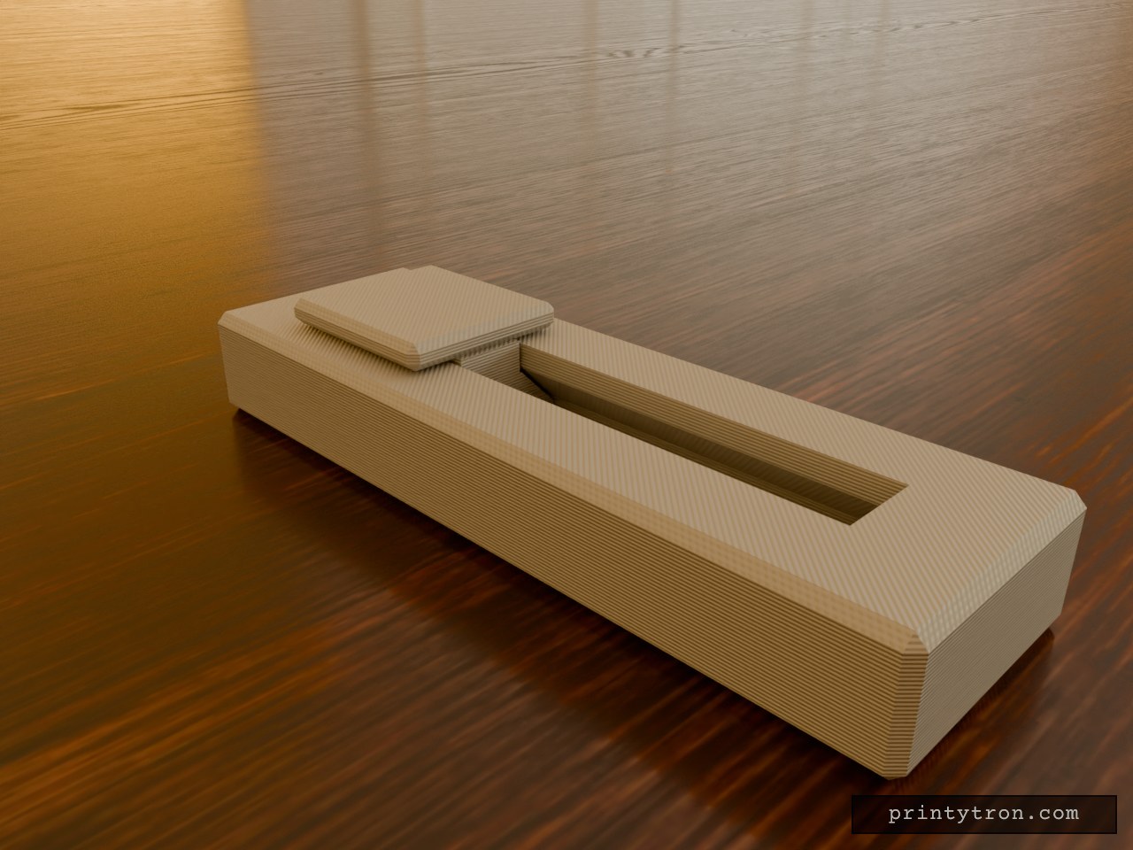
Fidget Slider Toy, Captive Print-in-Place
A fidget slider that prints already assembled, so there is no loose weight to lose and nothing to glue. The slider is captured in an enclosed dovetail track and cannot fall out. It runs 40 mm end to end and clicks at each stop instead of rolling freely. What it does Slides back and forth along a closed track in an 80 x 25 mm body. A small bump on the track floor at each end of travel drops into a dimple under the slider and gives the click. The dovetail profile holds the slider down, so it cannot lift out of the rails. Numbers that matter Body: 80 x 25 x 11 mm, with the slider top reaching 14 mm. Slider: 20 mm long, 18 mm wide cap. Travel: 40 mm. Clearance between slider and track: 0.4 mm per side. This is what lets it move after printing. Click bump: about 0.6 mm of interference against the 0.4 mm gap. Reduce the bump height if it feels too stiff. Printing Print flat, body base down, with no supports needed inside the track. Use a well-tuned printer. A 0.4 mm gap fuses easily if the flow is too high. After printing, work the slider back and forth a few times to break any thin bridging between the slider and the rails. Two colours show as separate parts in the preview, but the print is one job.
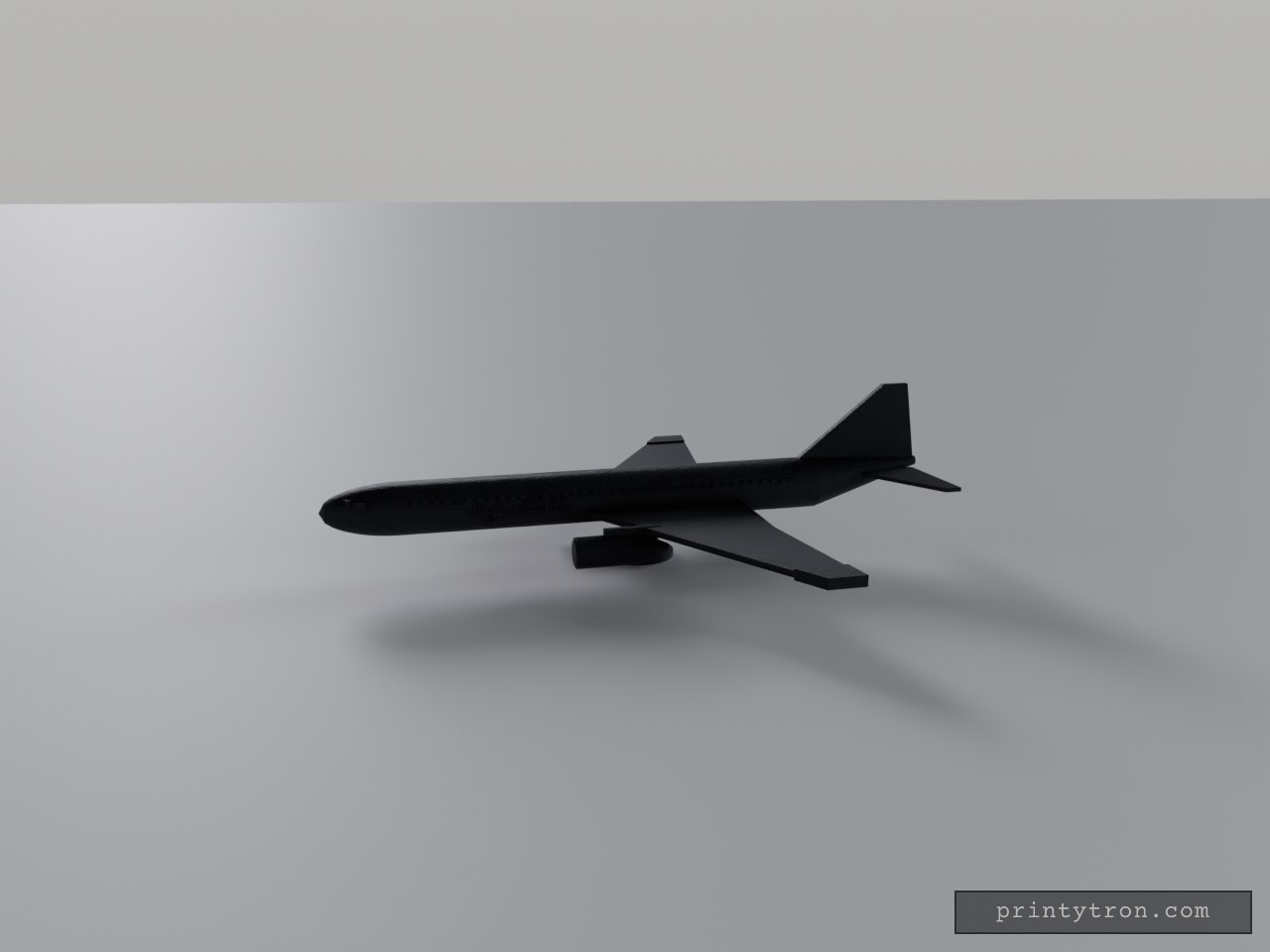
Virgin-Rot-Weiß: Boeing 777 Standmodell
Virgin-Rot auf Weiß: Der weiße Rumpf mit rotem Bauchstreifen, das rote, gepfeilte Seitenleitwerk und die roten Triebwerke an den Flügeln bringen den Virgin-Atlantic-Look auf den Tisch. Die Boeing 777 steht als Standmodell mit gewölbter Nase, hochgezogenem Heck, blauen Fensterreihen und schrägen Cockpitscheiben; auf beiden Rumpfseiten steht „virgin atlantic“ in roter Schrift. Einläufe und Ständer sind weiß gehalten. Was dran ist: Maßstab etwa 1:320 – rund 230 mm lang und 200 mm Spannweite Gepfeilte Flügel mit roten Spitzen, Triebwerke an Pylonen mit weißen Einläufen Fensterreihen und Cockpitfenster in Blau, roter Bauchstreifen und Schriftzug „virgin atlantic“ Kein Fahrwerk – ein weißer Ständer trägt das Modell Farben getrennt wählbar: Weiß für Rumpf, Flügel, Höhenleitwerk, Einläufe und Ständer; Rot für Leitwerk, Triebwerke, Spitzen, Streifen und Schrift; Blau für die Fenster