GOpro fieur skadis
Created 1 months ago
Description
A sturdy, mechanical mount that attaches standard GoPro gear to an IKEA SKÅDIS pegboard. Unlike standard static mounts, this design features a vertical hinge axis allowing the camera to pan left and right, making it ideal for overhead workspace recording or fixed security angles.
The design relies on an M5 bolt and nut to clamp the vertical rotation axis firmly in place once the angle is set. The quick-release buckle block prints separately for optimal layer orientation, plugging into the rotating base plate.
Assembly
- Base: Locks into two standard SKÅDIS slots without tools.
- Mechanism: Insert an M5 bolt through the side clamp, trap an M5 nut in the hex recess, and tighten with the printed knob.
- GoPro Buckle: Glues or presses onto the two registration pegs atop the rotating platform.
- Slide your standard GoPro helmet buckle straight in.
Photos
Technical views
More like this
Explore more in Automotive, RC & Hobby →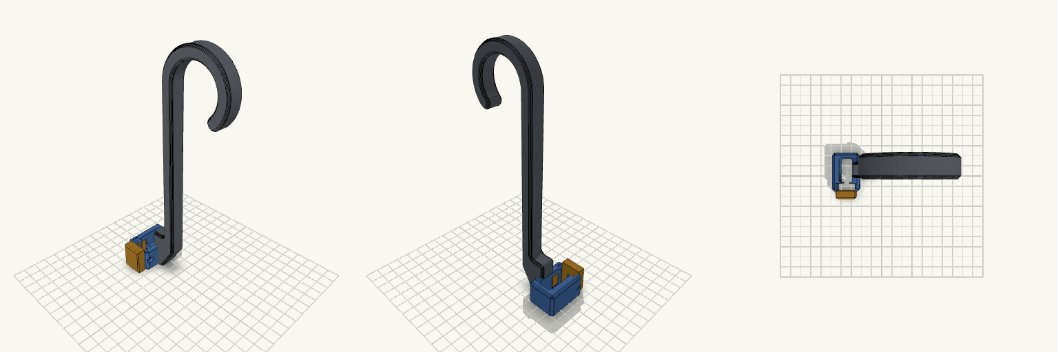
Gancho de Garrafa com Braçadeira Snap
Gancho de garrafa de treino em J, 200 mm, com braçadeira bipartida na base: corpo fixo ligado à haste e tampa separada que fecha por encaixe de pressão ao redor da alça de 12 × 24 mm. Pontos de remix Snap-fit: ganchos flexíveis de 8 mm de comprimento, 1,8 mm de espessura e ressalto de 0,6 mm (armlen, armt, ridge). Entrada em rampa, retenção reta. Folga: 0,2 mm entre tampa e corpo (gap). Trava extra: furo M3 em gota atravessando tampa e corpo, com porca sextavada embutida no lado +X. Paredes: wallx (6,4 mm) e wallf (7,5 mm) definem o tamanho externo; reduza se o furo M3 for dispensado. Haste e gancho: inalterados, seção 10 × 14 mm, bojo de 40 mm, boca de 34 mm. Combina com: parafuso M3 e porca M3 (opcionais); imprima corpo e tampa separados em PETG ou PLA.
Pinch-Feed Drive Roller, Print-Ready
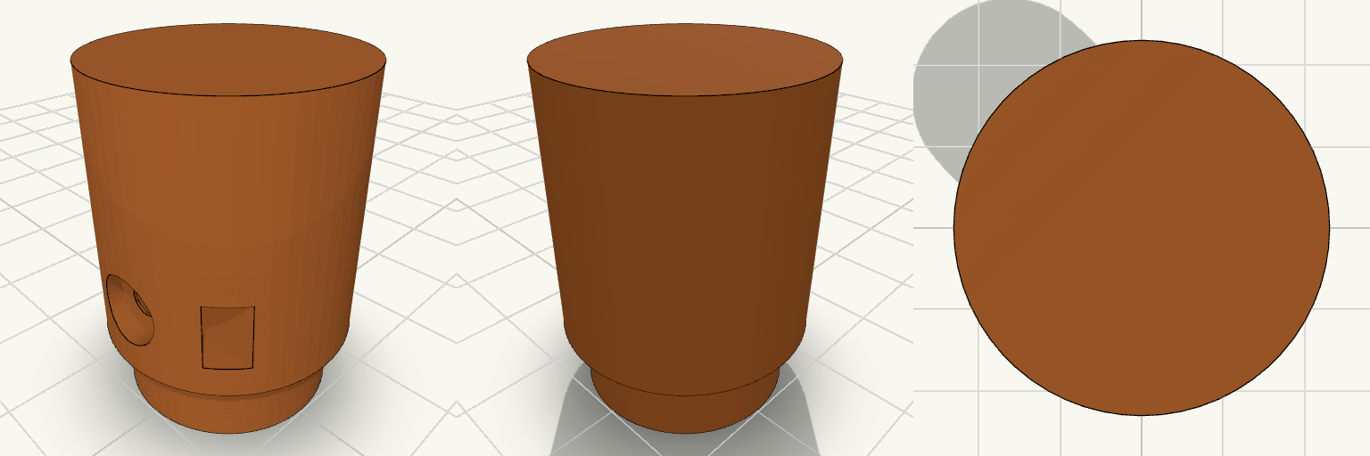
A knurl-free drive wheel for a pinch-feed wire feeder, built like a small industrial pulley: a 24 mm roller with a hub on one side and a blind D-bore that slips over a 5 mm D-shaft. The model is just the roller, standing on its hub and ready to slice. Design notes Blind D-bore, open on the hub face and closed by a wall on the far end, so the closed end shows which side stays out. M3 grub screw hole with a trapped hex nut that slides in through a slot open to the rim. Counterbored screw recess 2 mm deep, so a headed M3 screw sits below the surface and a nylon or TPU sleeve goes on smooth. Hub spaces the roller off the motor face so the two do not rub. Printing Stands on the hub with the bore opening onto the bed, so there is no bridging inside the bore and no supports are needed. Printing upright keeps the roller round. Suggested: PETG, ASA or nylon, 3 or more walls, 25–30% infill.
Wall-Mounted Jack Stand Hanger small support
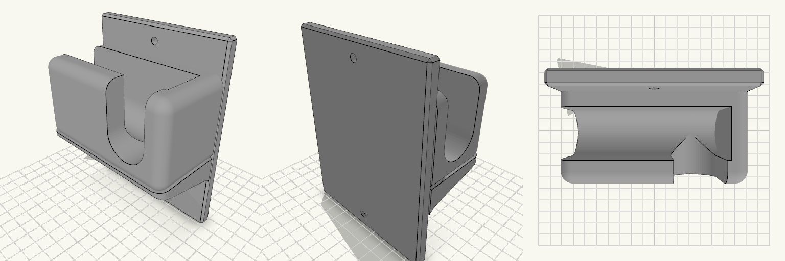
A wall-mounted holder that keeps a 3-ton jack stand off the garage floor and within reach. The flat vertical back plate carries a U-shaped cradle in the centre, open at the top so the stand's bar drops in and lifts out. The cradle is open through the middle and closed by a 10 mm wall at each end, so the bar cannot slide sideways off the holder. The front wall of the cradle is a 13 mm lip that catches the bar and stops it sliding forward. The cradle walls are rounded with a 7 mm radius on every edge except the one against the back plate, and the inner floor is a rounded half-cylinder trough running the length of the opening, 28 mm across to match the seat, so a round bar or handle lies in it without rocking. The holder prints as one piece with no assembly, and it is sized for a 3-ton jack stand and its handle. A compact gusset supports the cradle underneath and runs the full 100 mm width of the cradle, so the end walls sit flush on it instead of overhanging. Its corners carry the same 7 mm radius as the cradle, so the walls run down into it with no ledge. The underside is an S-curve: it leaves the back plate 39 mm up, sweeps out and finishes running straight up the back of the front lip, meeting both surfaces tangentially so there is no crease where it joins. Keep it around this size — trimming it much further leaves the cradle with little support against the weight of a loaded stand. The jack handle hangs from two cuts, so it drops in from above rather than being threaded in from the front. A 28 mm slit in the front wall, open at the top, sits 24 mm right of centre and stays clear of the right edge, which runs fully to the front and stands even with the left wall. Opposite it, the left end wall carries a matching 28 mm notch, open at the top. Both cuts share the cradle trough's floor depth, with their centreline at 80 mm up and their floors bottoming out at 66 mm. The slit floor starts at the trough centreline with a rounded blend where the two meet, so the handle slides from the trough into the slit and notch without a step and hangs clear below. The cradle walls stand 55 mm tall, topping out at 110 mm up, which leaves about 16 mm of wall above a 28 mm handle resting at 80 mm. Overall: 100 mm wide, 130 mm tall, 57 mm deep Cradle: U-shaped, 28 mm bar seat, open top, open through the middle, 10 mm end wall each side, rounded floor trough Cradle walls: 55 mm tall, tops at 110 mm, rounded at 7 mm Bar opening: about 80 mm between end walls Front lip: 13 mm thick Handle slit: 28 mm, open at the top, set 24 mm right of centre in the front wall, floor blended into the trough Left end wall: matching 28 mm notch, open at the top, for the other side of the handle Floor height: slit, notch and trough all bottom out at 66 mm Gusset: full cradle width, 7 mm rounded corners, S-curve underside tangent to the back plate and the front lip, meeting the plate 39 mm up Mounting: one countersunk screw hole above the cradle and one below; use 5 mm or larger screws into a stud or suitable anchor Material: grey PETG suits the load and garage conditions; edges are chamfered Check that the stand's bar fits the 28 mm seat and the 80 mm opening, and that the handle fits the 28 mm slit and notch before printing. If the bar or handle is larger, widen the seat or the cuts to match.
Triple Socket Adapter Floor Cradle
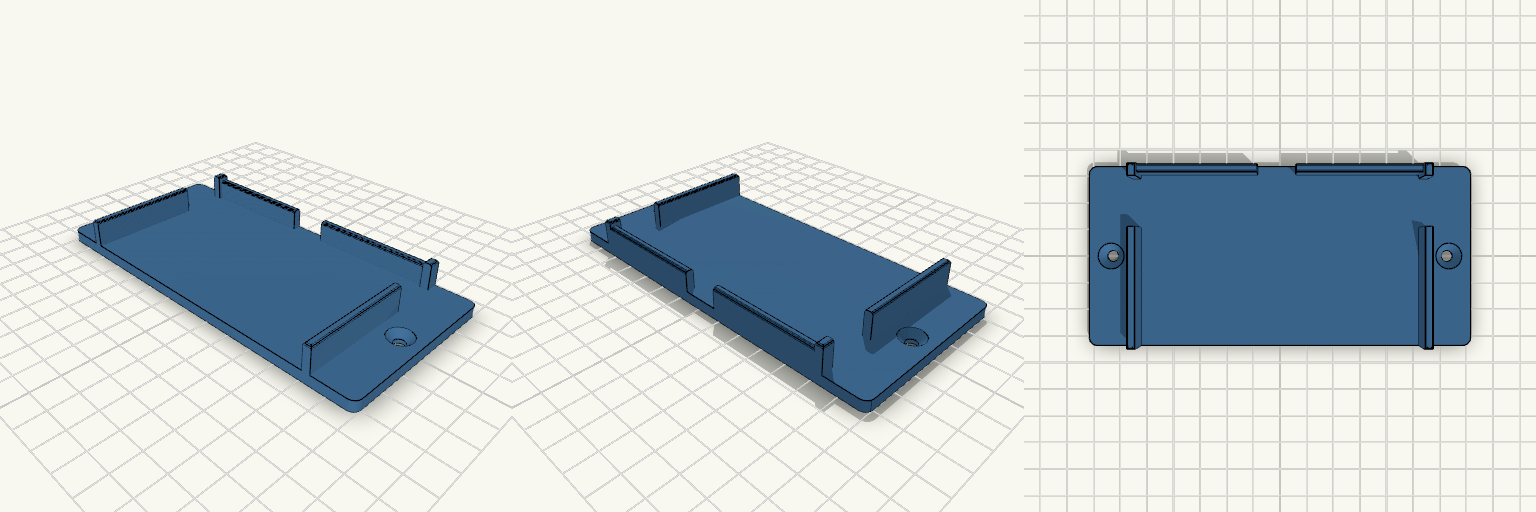
What it's for A one-piece floor cradle that holds a triple 12V socket adapter horizontally under a dashboard. The front and top stay open, so the sockets and power switches remain reachable, and side windows keep the side USB ports clear. Dimensions Adapter: 100.4 x 60.85 x 31.72 mm, about 1 mm clearance Side walls: 3 mm thick, 14 mm tall Side windows: 18 mm long, centred 51.38 mm from the front (plus 1 mm clearance) Back lip: 12 mm tall with reinforced corners Mounting ears: 16 mm each end, countersunk screw holes Remix ideas Change the window length to fit a different USB port. Add a third screw hole at the back. Lengthen the ears for wider mounting.
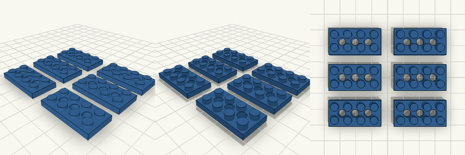
Technic Plate 2x4 With Holes, Set of 6
A 2x4 plate with no way to pass a Technic pin or axle through it is a dead end in a studless build. This plate has three holes on the centre line, so pins and axles go straight through. Six are laid out flat for one print run. Key numbers Plate: 32 x 16 mm, 3.2 mm thick, studs on 8 mm pitch Studs: 4.8 mm diameter, 1.8 mm tall Holes: three, 4.8 mm diameter, on the centre line, 8 mm apart Print: flat, no supports, 0.2 mm layers; test one first to check clutch fit
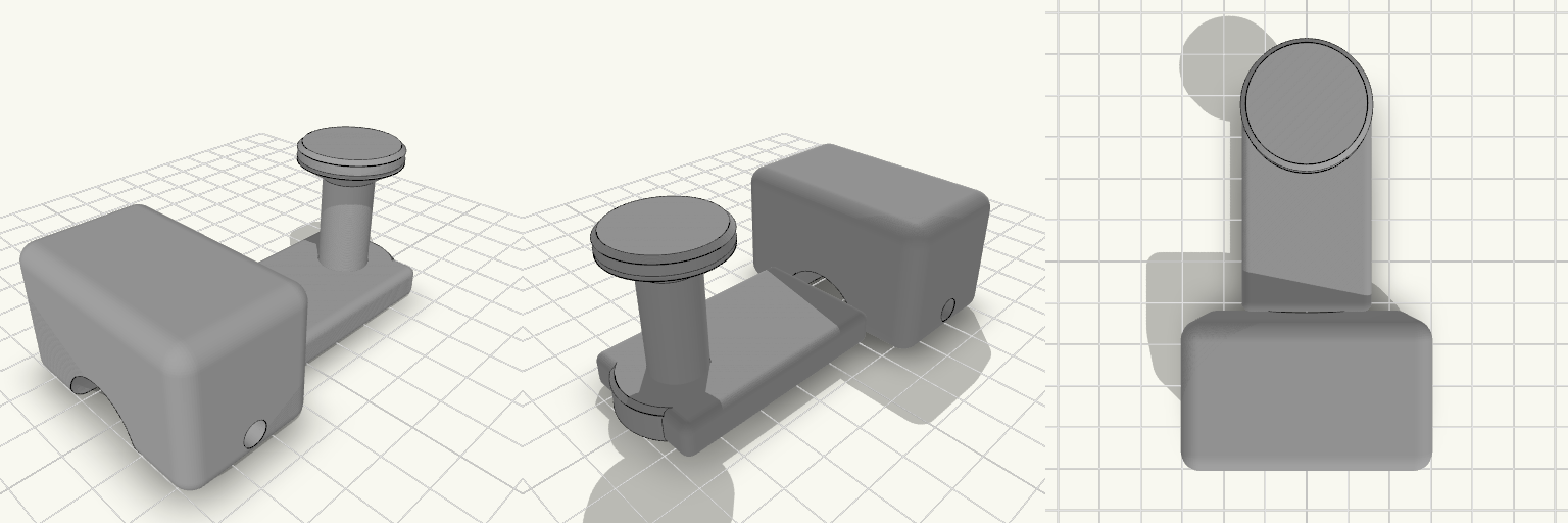
Mountain Bike Wagon Hitch with Capped Post
What it's for A hitch that lets a mountain bike pull a wagon by its C-shaped handle. The bike side is a clamp block that grips the frame tube with a pinch bolt; a flat arm carries that back to an upright post. The post ends in a 12 mm neck with a flared cap on top, so the wagon's C-handle drops over it and cannot slide off while you ride. Clamp block with a 22 mm bore and a single pinch bolt — check this bore against your actual seat stay or axle tube before printing, and scale the clamp if your tube differs Flat arm sets the post behind the clamp, clear of the frame Capped neck holds the handle on but still lifts off when you want to unhitch Dimensions Overall footprint on the plate: 50 × 83 × 38 mm Clamp bore: 22 mm Post neck: 12 mm diameter, about 22 mm tall, with a flared cap above it Print notes Print the part as oriented on the plate so the clamp bore and the neck stay round and the arm keeps its strength across the layer lines. A tough filament such as PETG or ABS/ASA suits a part that takes trail vibration and towing loads better than plain PLA. Remix ideas Resize the clamp bore for thinner or thicker frame tubes, or split the clamp into a two-bolt version for rougher trails Lengthen the arm to move the post further back for wider cargo or tighter frame clearance Swap the capped neck for a ball or pin joint if you want the wagon handle to pivot more freely