Lego 6-Stud Railcar Cab studs on top
Created 16 days ago
Description
A 6-stud-wide cab front modelled after modern sloped-nose Irish railcars (such as the 22000 Class).
Fitment
- Base footprint: 6 x 2 studs (48mm x 16mm).
- Height: 3 standard bricks (28.8mm).
- Mounting: Drops onto standard 8mm-pitch studs.
The part is designed as a solid block rather than a hollow shell, using 5.1mm clearance holes in the base. This provides FDM printers with a clean, support-free printing experience while maintaining a firm friction fit on standard brick ecosystems. The rear face is completely flat, allowing seamless mating with standard brick walls behind the cab.
Images
More like this
Explore more in Automotive, RC & Hobby →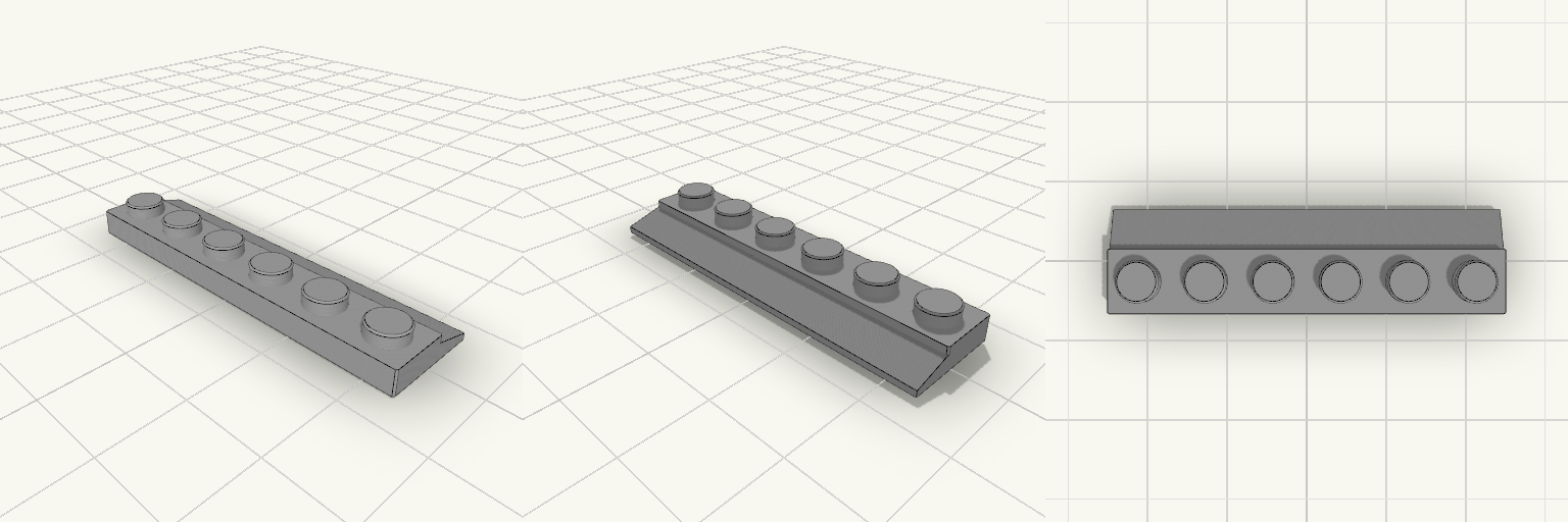
Lego piece for wagon door runner with thinner teeth bit slightly smaller
Wagon door runner to replace 3 off 15208 bricks Version with slightly too large slope
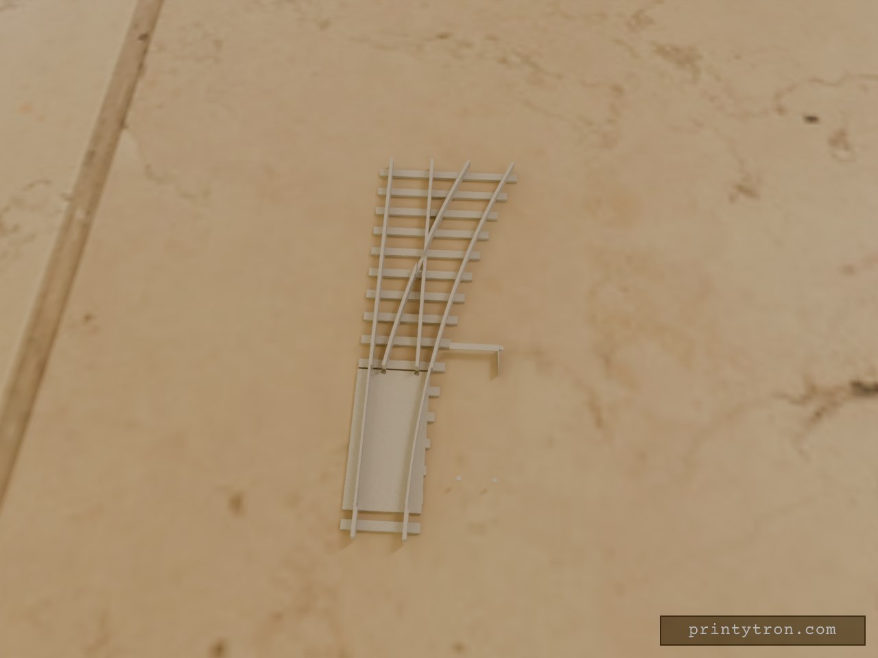
Lego style R120 Fixed Track Switch
What it's for A static, non-moving track switch designed for interlocking brick train systems. It features an R120 geometry curve diverging from a standard straight section, complete with clearance flangeways for wheelsets and bottom anti-studs for baseplate mounting. Dimensions Length: 384 mm (48 studs) Curve Radius: 960 mm (120 studs) Rail Height: 9.6 mm (above ties) Overall Height: 12.8 mm Compatibility Mates with standard brick-built train track ecosystems. Flangeways are sized to clear standard rigid wheelsets.
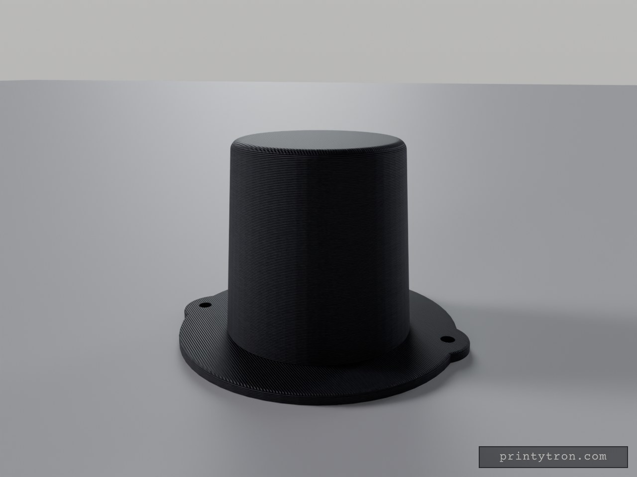
Feline Cranial Top Hat
Miniature top hat scaled for the cranial dome of standard domestic felines. Mates directly to the top of the head using a user-supplied elastic retention strap routed through the brim extensions. Fitment: Best suited for domestic shorthair profiles. Not verified for large breeds (e.g., Maine Coon) or flat-faced profiles. Clearance: 60mm main brim diameter. Check this measurement against the subject's ear spread before printing. Retention: Features twin 3mm anchor bores to accept standard elastic cord. Tie off on the underside of the brim.
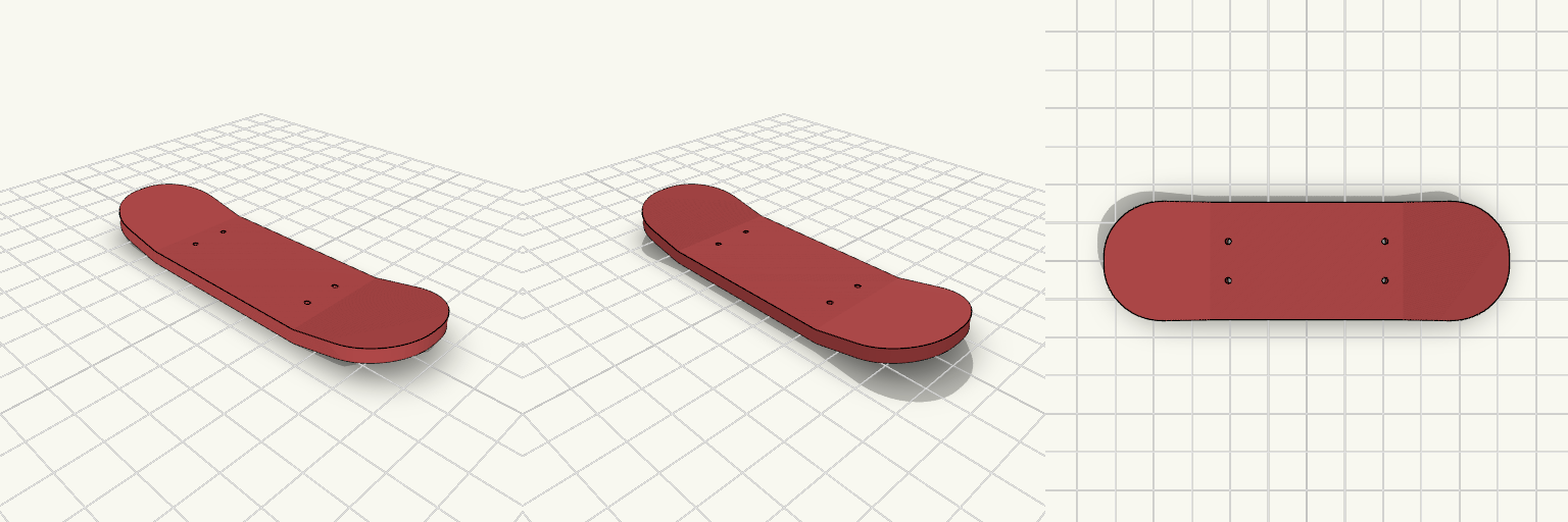
Flat-Profile Fingerboard Deck
A classic double-kicktail mini skateboard deck, sized for standard fingerboard hardware. The baseline dimensions are a 100mm total length, 30mm width, and 2.5mm thickness, which hits the sweet spot for a standard grip feel. The mounting pattern drops right onto standard 32mm fingerboard trucks. Remixing Parameters If you take this into CAD to build your own pro-model, the key geometry hooks are: Kick Angle: Currently pitched at 22 degrees for a medium-high pop. Wheelbase: The truck centers sit 52mm apart. Concave: This base version is entirely flat across the width to print beautifully face-down without supports. Add a subtractive cylindrical sweep across the top face if you want real side-to-side concave.
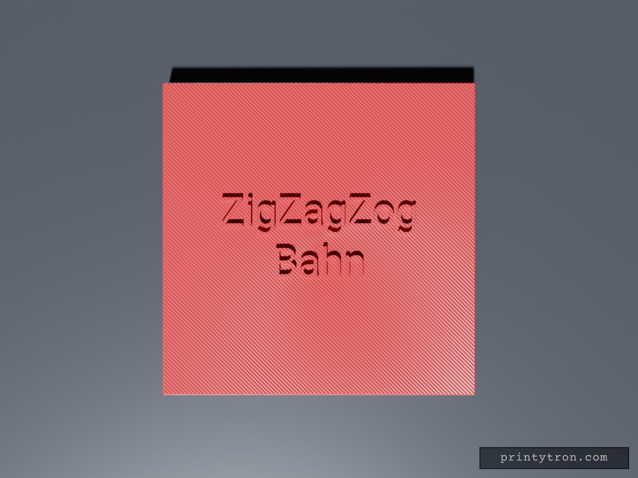
ZigZagZog Bahn Railway Tile
Custom 6x6 building block tile covering bare studs with raised railway lettering. A dead-flat top piece that refuses to pop loose once seated. Footprint: 6x6 standard block pitch (47.8mm square) Clearance: 0.2mm gap tolerance for side-by-side placement Mount: Underside tubes clutch standard studs
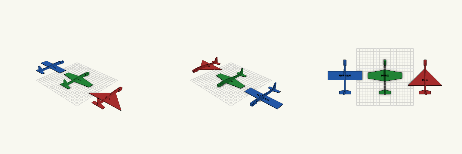
2AeroTest — Glider Wing Comparison
A set of three flat-printed aerodynamic test gliders designed for direct side-by-side flight comparison. Built specifically to eliminate variables, all three models share an identical streamline fuselage, tail assembly, weight distribution, and a total wing planform area locked exactly at 3600 mm². The only variable is the main wing geometry. Design Geometry Total Wing Area: 3600 mm² per aircraft Wing Thickness: 0.8 mm (prints as a solid, flexible surface) Rectangular Wing: 120 mm span × 30 mm uniform chord Tapered Wing: 120 mm span, tapering from a 40 mm root to a 20 mm tip chord Delta Wing: 120 mm span, tapering from a 60 mm root to a 0 mm tip chord Print Notes These are designed as print-in-place monolithic objects. The entire flat bottom of the aircraft (wing, tail, and fuselage belly) rests on the build plate at Z=0. Because the wings are only 0.8 mm thick, they print entirely solid in 4 standard 0.2 mm layers without needing supports. For simulated dihedral, gently bend the wings upward close to the fuselage immediately after removing them from a warm build plate.