Stepped pH/EC Probe KCl Holder
Created today
Description
A weighted desktop stand that holds a pH/EC probe tip-down in a small pool of KCl. The probe drops in and its flange rests on the top seat, so the tip stays at a fixed depth.
Built around caliper readings: 18 mm round tip (12 mm submerged), a barrel widening to 20 mm with an o-ring, and a 28 mm flange 2 mm above the o-ring.
Remix hooks
- Pocket diameter: 19.5 mm (18 mm tip plus 1.5 mm clearance). Tighten it to use less KCl.
- Barrel bore: 21 mm. Keep it above 20 mm so the o-ring clears.
- Seat: 29.5 mm wide, 3 mm deep, for the 28 mm flange. Add a lid or a drip ring here.
- Tip-to-flange distance: 26 mm, with a 1 mm gap above the pocket floor. Changing it moves the KCl depth.
- Body and base: 40 mm column on a 60 mm, 8 mm base, 65 mm tall overall. Widen the base or add a pocket for weights if it tips.
- Pairs with: a small cap or cover to slow KCl evaporation, or a second pocket for a calibration buffer.
Images
More like this
Explore more in Desk & Tech →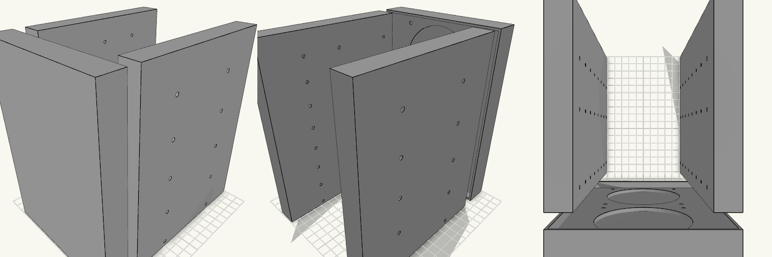
Octobay — 5.25" to 3.5" Drive Cage
Octobay turns a five-bay stack of half-height 5.25" slots into room for eight 3.5" drives, and adds a 25 mm front cage that carries two 92 mm fans. The outer side faces take M3 heat-set inserts, so the whole cage screws into the case's 5.25" rails instead of resting on them. Everything is one printed part: the drive stack, the side mounting blocks and the fan cage print as a single body. Because the fans close off the front, drives now load from the back. The fan cavity behind the grille is hollow, so air still passes through to the drive stack. Dimensions Overall: 145 mm wide × 197.5 mm deep × 205.5 mm tall Fits: five half-height 5.25" bays Holds: eight 3.5" drives, stacked vertically Drive channel: 102.6 mm wide — 1 mm of play around a 101.6 mm drive Mounting 20 insert holes, 10 per side, for M3 heat-set inserts — 4.2 mm across and 6 mm deep Two insert holes per bay, at 41.3 and 117.5 mm from the front, 6.35 mm above each bay floor Solid blocks sit behind each hole to give the inserts something to bite into Three M3 screw holes per side per drive, at 14, 76.6 and 117.6 mm from the front Cross ribs sit clear of the screw holes so a screwdriver can reach every fastener Fan cage Two 92 mm fans, stacked vertically on the 25 mm front section 88 mm fan openings with 4.4 mm screw holes on the standard 82.5 mm square pattern Hollow cavity behind the fans feeds air to the drive channels Print notes Drive channels are open at the back, top and bottom, and the gaps between the inner and outer side walls are open for cable routing. Screw and insert positions and the 205.5 mm height follow common 5.25" bay standards; they have not been checked against a specific case, so measure your bay rails and drives before printing.
Fidget Slider Toy, Captive Print-in-Place
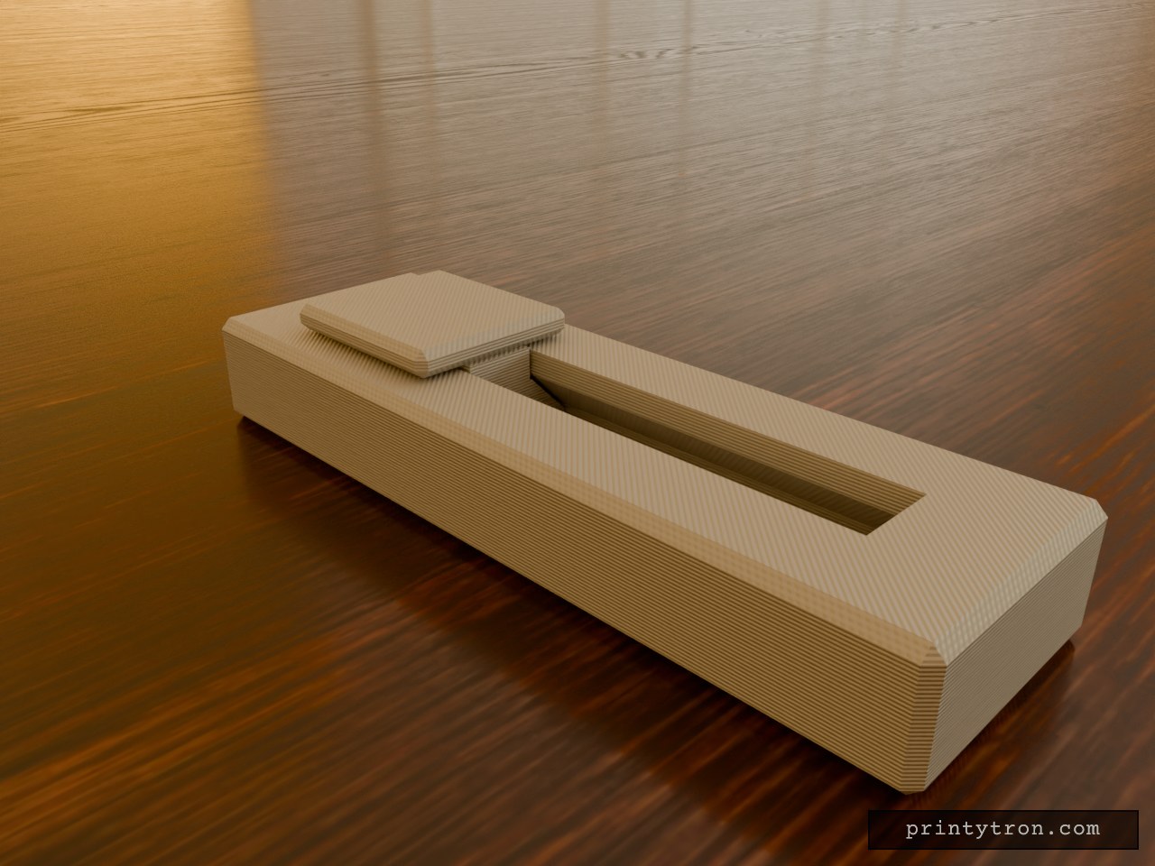
A fidget slider that prints already assembled, so there is no loose weight to lose and nothing to glue. The slider is captured in an enclosed dovetail track and cannot fall out. It runs 40 mm end to end and clicks at each stop instead of rolling freely. What it does Slides back and forth along a closed track in an 80 x 25 mm body. A small bump on the track floor at each end of travel drops into a dimple under the slider and gives the click. The dovetail profile holds the slider down, so it cannot lift out of the rails. Numbers that matter Body: 80 x 25 x 11 mm, with the slider top reaching 14 mm. Slider: 20 mm long, 18 mm wide cap. Travel: 40 mm. Clearance between slider and track: 0.4 mm per side. This is what lets it move after printing. Click bump: about 0.6 mm of interference against the 0.4 mm gap. Reduce the bump height if it feels too stiff. Printing Print flat, body base down, with no supports needed inside the track. Use a well-tuned printer. A 0.4 mm gap fuses easily if the flow is too high. After printing, work the slider back and forth a few times to break any thin bridging between the slider and the rails. Two colours show as separate parts in the preview, but the print is one job.
Bearing-Driven Tri-Lobe Fidget Spinner
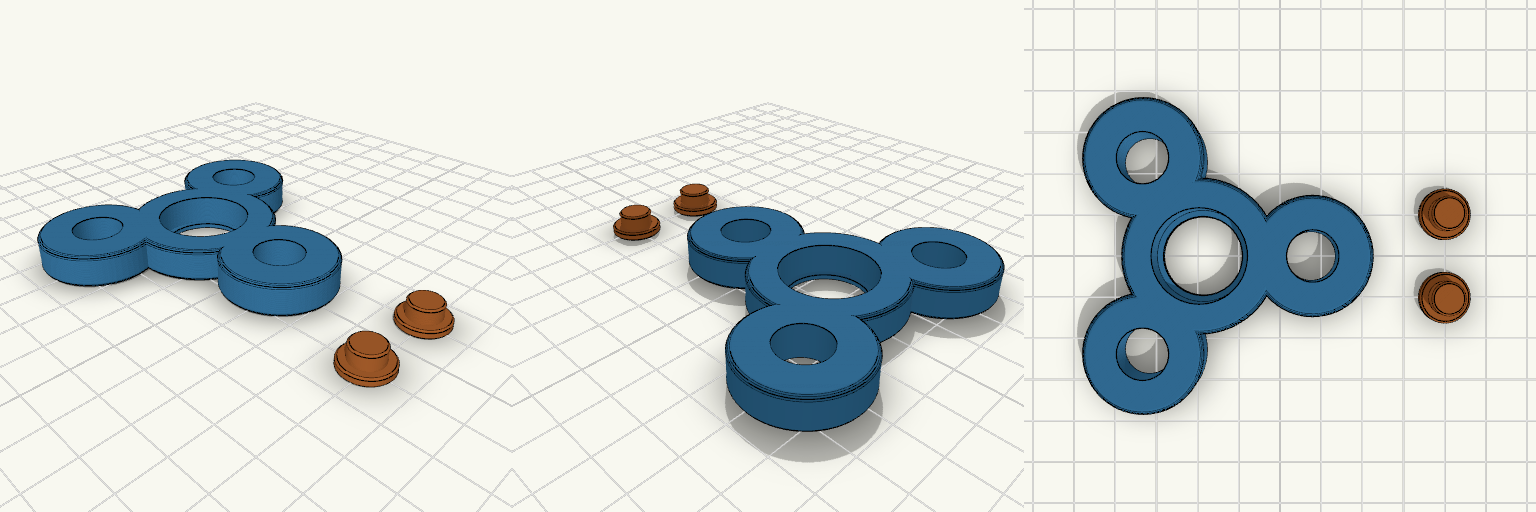
A classic three-lobe hand spinner, the shape every desk drawer has seen, rebuilt around a real 608 skate bearing so it spins freely for a long time. The body has a bearing pocket in the centre, a lip underneath to hold it, and weight-saving holes in each lobe. Two small caps press into the bearing's inner ring from either side to make the finger pads. Notes You need: one 608 bearing (8 × 22 × 7 mm). Print: body flat; the two caps print flat-side down beside it. No supports. Assembly: press the bearing into the pocket from the top, then push one cap in from each side until they meet. Tuning: if the bearing is loose or tight in the pocket, adjust the pocket diameter slightly. Remix: the lobe holes can be enlarged to take 608 bearings as extra weights.
Lockdown — Dev Board Case With Camera Eye
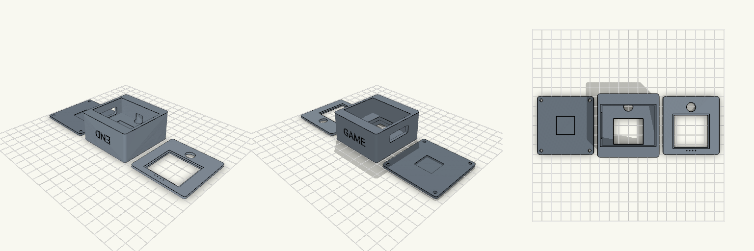
Lockdown is a three-part enclosure for a Freenove ESP32-S3 WROOM CAM board with a 35.5 × 33.5 mm display. The front bezel turns the screen into a face, with a 9.6 mm camera eye above the window. The side wall carries one wide cable opening, so USB-C plugs and cables pass straight through the housing. Features 58 × 60 mm footprint across chassis, back cover and bezel Screen pocket with a support ledge and a flex-cable opening 9.6 mm camera bore lined up with the bezel eye Single 26 × 9 mm cable pass-through on the +X wall, raised for a high-mounted board Four M3 screws from the back Embossed-in END and GAME text on the end walls Print notes Print the three parts flat on their backs. PETG works well.
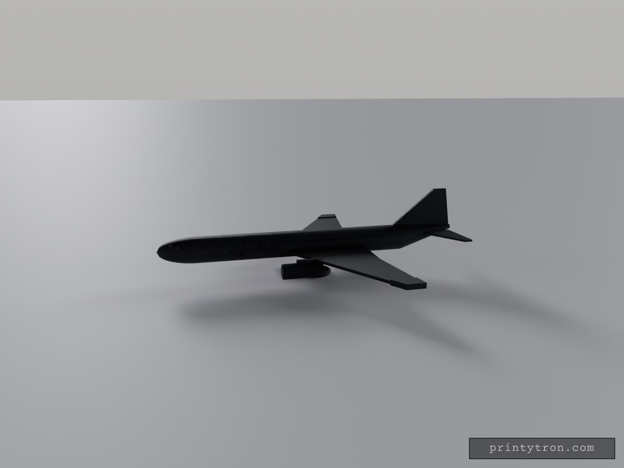
Virgin-Rot-Weiß: Boeing 777 Standmodell
Virgin-Rot auf Weiß: Der weiße Rumpf mit rotem Bauchstreifen, das rote, gepfeilte Seitenleitwerk und die roten Triebwerke an den Flügeln bringen den Virgin-Atlantic-Look auf den Tisch. Die Boeing 777 steht als Standmodell mit gewölbter Nase, hochgezogenem Heck, blauen Fensterreihen und schrägen Cockpitscheiben; auf beiden Rumpfseiten steht „virgin atlantic“ in roter Schrift. Einläufe und Ständer sind weiß gehalten. Was dran ist: Maßstab etwa 1:320 – rund 230 mm lang und 200 mm Spannweite Gepfeilte Flügel mit roten Spitzen, Triebwerke an Pylonen mit weißen Einläufen Fensterreihen und Cockpitfenster in Blau, roter Bauchstreifen und Schriftzug „virgin atlantic“ Kein Fahrwerk – ein weißer Ständer trägt das Modell Farben getrennt wählbar: Weiß für Rumpf, Flügel, Höhenleitwerk, Einläufe und Ständer; Rot für Leitwerk, Triebwerke, Spitzen, Streifen und Schrift; Blau für die Fenster
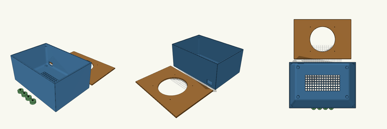
Mini-Server-Box with Feet, Lid and Fan
What it's for A solid-walled enclosure for hiding and cooling equipment. Every side wall is closed, and the only airflow path is a sturdy grid cut into the floor, so the box stays dark and quiet from the sides. A 30 × 20 mm cable hole in the lower rear corner lets wiring in and out, and the flat lid lifts off for access. The model prints as separate pieces: the box, the lid and four feet. The lid is a flat plate with a locating lip underneath, slightly larger than the box on every side so it overhangs and can never drop inside. Each foot carries its own coarse threaded stud, so the feet screw directly into matching threaded holes in the floor bosses with no separate fasteners. Dimensions Box: 290 × 200 × 130 mm, with 4 mm walls, solid on all four sides, an 8 mm floor, and a 50 mm solid border around the floor grid. The floor grid is centred on the narrower floor. The thicker floor makes the mesh bars deeper, so airflow per opening drops slightly. Inside fillets: 10 mm radius on the vertical corners and the floor-to-wall edges, stopping 15 mm below the rim. The top 15 mm stays square so the lid and its lip fit without changes. Lid: 294 × 204 mm, 9 mm overall with a 5 mm plate and underside lip; overhangs the box by 2 mm on all sides; 140 mm fan opening and four 3 mm fan screw holes at 124.5 mm center-to-center. Cable hole: 30 × 20 mm in the rear wall, set 20 mm from the left edge and 12 mm above the bottom, inside the solid section so it doesn't weaken the corners. Feet: four solid 24 mm discs, 10 mm tall, each with a 6 mm thick, 8 mm long threaded stud on top; 18 mm overall. The studs use a 1.5 mm pitch. Foot sockets: four corner bosses widened to 14 mm, with threaded holes 6.6 mm across and 11 mm deep at the same 1.5 mm pitch, giving about 0.6 mm clearance on diameter. Print notes Print the box, lid and feet separately. Print the lid lip-side up so its flat face sits on the bed and the lip rises clear of the plate. The floor grid benefits from enough perimeters to keep the bars sturdy. The threads have not been test-fitted; if the feet bind, raise the socket diameter slightly, and if they wobble, lower it. Test-fit the fan and check its screw-hole spacing before committing to a full print. Remix ideas Add a removable filter frame behind the fan opening. Add internal standoffs or a shallow tray for mounting equipment inside. Resize or duplicate the rear cable port for thicker cable bundles. Swap the floor grid for a denser or more open pattern to change the airflow.