Lockdown — Dev Board Case With Camera Eye
Created 2 days ago
Description
Lockdown is a three-part enclosure for a Freenove ESP32-S3 WROOM CAM board with a 35.5 × 33.5 mm display. The front bezel turns the screen into a face, with a 9.6 mm camera eye above the window. The side wall carries one wide cable opening, so USB-C plugs and cables pass straight through the housing.
Features
- 58 × 60 mm footprint across chassis, back cover and bezel
- Screen pocket with a support ledge and a flex-cable opening
- 9.6 mm camera bore lined up with the bezel eye
- Single 26 × 9 mm cable pass-through on the +X wall, raised for a high-mounted board
- Four M3 screws from the back
- Embossed-in END and GAME text on the end walls
Print notes
Print the three parts flat on their backs. PETG works well.
Images
More like this
Explore more in Desk & Tech →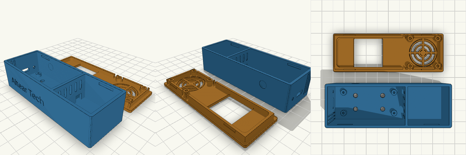
Case ESP32 + LoRa com Display e Cooler
Case compacto para ESP32 e módulo LoRa SX1278, com tampa de encaixe por pressão, janela para display TFT 1.44" e cooler na tampa. Ganchos para remix Altura interna (IH = 21 mm): altura total de 24 mm. Aumente se o LoRa ficar justo. Furação do cooler: quadrado de 24 mm com pinos de 5 mm e furo de 2,4 mm. Ajuste para outro tamanho de cooler. Janela do display: 26 × 26 mm na tampa. Combina com um suporte interno para o módulo. LoRa: sem canaletas internas. Dá para adicionar suportes na medida da sua placa. Ranhuras inferiores: duas ranhuras de 4 mm para cabos entre as placas.
Modular Voice Assistant Enclosure with Rotating Desk Dock
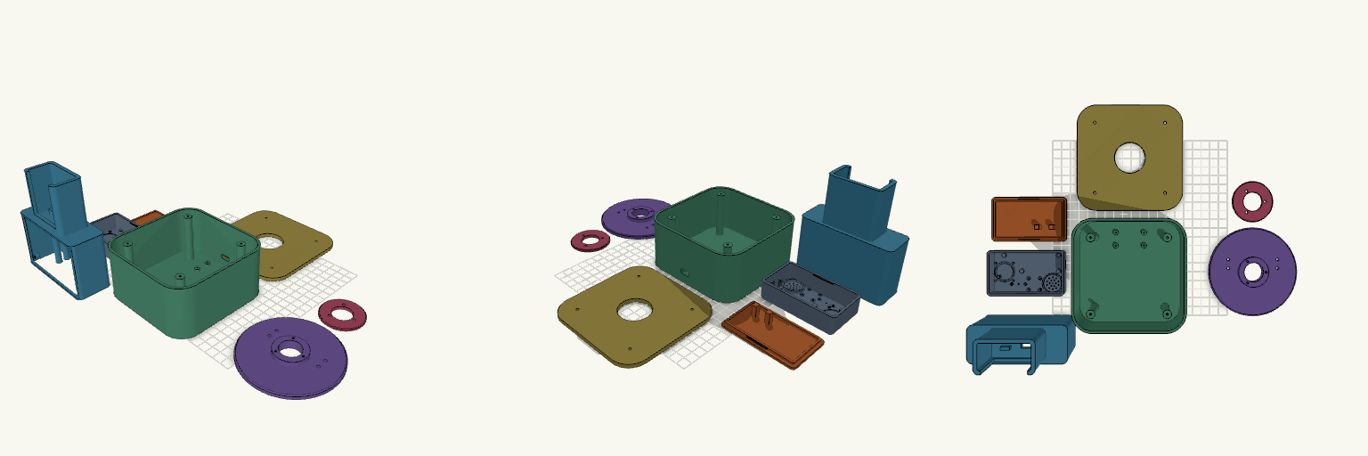
A two-part enclosure system for a modular AI voice assistant: a pocket-sized "Brain" that works on its own, and a desktop station that docks it, swivels a full 360° and carries a 3.5-inch touchscreen behind a removable bezel. Both halves share the same matte-black design language — rounded corners, smooth surfaces and 2–2.5 mm walls — and print as eight separate pieces. What it's for Brain — houses an ESP32-S3 N16R8 board, an INMP441 I2S microphone, a MAX98357A amplifier and a 20 mm speaker behind a grille. A circular LED ring glows through a 0.8 mm front skin for listening, thinking and speaking states; there is no display of its own. A USB-C port sits on the short end, and the unit runs standalone once lifted off the dock. Desk station — a weighted base with a bolted lid carries a swivel plate and the dock tower. The Brain drops into the tower pocket from above with its face still visible, and a USB-C plug cradle in the pocket floor lines up with the port. Display — the tower front takes a standard 98 × 56 mm touchscreen module in landscape, held on four M2 bosses and framed by a bezel that drops into a recess in the front face. Removing four screws frees the display for replacement, and a flat-cable slot below the opening routes the ribbon into the cavity. Rotation — the swivel plate's hollow stem passes through the lid, a retaining ring screws on underneath, and the cable runs down the centre of the stem, so the tower turns 360° without twisting the lead. Dimensions Brain: 85 × 50 × 25 mm overall, with a snap-fit rear cover. Desk base: 120 × 120 mm with 22 mm corner radii; base, lid and swivel plate stack to 65 mm. Dock tower: 104 × 40 × 119 mm, docking the Brain vertically above the display section. It overhangs the 100 mm swivel plate slightly at the front and rear corners. Display opening: 84 × 54 mm, with mounting bosses behind the wall at ±46 × ±25 mm and M2 pilot holes; bezel 100 × 60 × 2.5 mm. Walls: 2–2.5 mm throughout hollow cavities. Print notes Print the Brain shell face-down for a smooth front skin; the LED ring, microphone port and speaker grille all sit in that face. The rear cover snaps on with two bump-and-groove pairs along the long sides; pads on its inside hold the ESP32 down. The tower's internal floor and the display window bridge wide spans, so expect a little support in the dock tower only. Everything else is oriented to print without it. Print the bezel flat; it is a thin frame and needs no supports. PLA or PETG both work; four rubber-foot recesses under the base are worth filling. All eight pieces — Brain shell, rear cover, desk base, base lid, swivel plate, retaining ring, dock tower and display bezel — are separate. The lid bolts on at four corners and the display bezel screws in from the front. Compatibility The display bosses use M2 pilot holes; check your module's hole spacing before driving screws, since pinouts vary between boards. The dock pocket is sized for the Brain as drawn — if you change the Brain's shell, adjust the pocket in step. Remix ideas Lean the dock back a few degrees for a more natural viewing angle if you can accept the extra support. Swap the removable bezel for a blank panel or a vent if your build has no screen. Scale the docking pocket to fit a different companion device while keeping the same swivel mechanism.
SilentSOS Two-Piece Electronics Enclosure
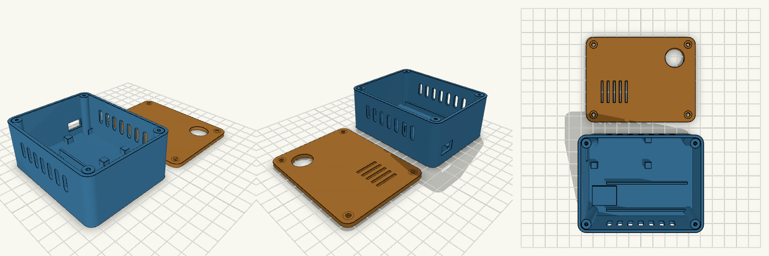
A 90 × 70 × 40 mm two-piece enclosure for an ESP8266 NodeMCU SOS alert device: a 37 mm tall base with 2 mm walls and a separate 3 mm lid, with 6 mm rounded vertical corners. The lid is printed flat and fastens with four M3 screws into corner bosses. Remix hooks Component mounting: no hole positions were guessed. The NodeMCU sits on four 5 mm locating pads at the board corners (49 × 26 mm area, nb, nbc). Once measured, add real standoffs in extraposts as [x, y] pairs and set post_pilot. Battery bay: two 1.5 mm rails 22 mm apart hold a cell of about 18 mm diameter, 65 mm long. Move or space them for other cells. DC-DC zone: a low 20 × 16 mm pad, free to move or resize. USB opening: 13 × 8 mm in the short wall, aligned to the NodeMCU position. SOS button: 16 mm hole in the lid (btnd, btnpos). Ventilation: seven slots in each long wall plus five slots in the lid. Screws: 2.6 mm pilots in the bosses, 3.4 mm countersunk lid holes. Pairs well with heat-set inserts in the bosses, or a gasket strip for a dust-resistant fit. Export base and lid as separate STLs by rendering each module alone.
Crossfader Knob 20x8x10 mm
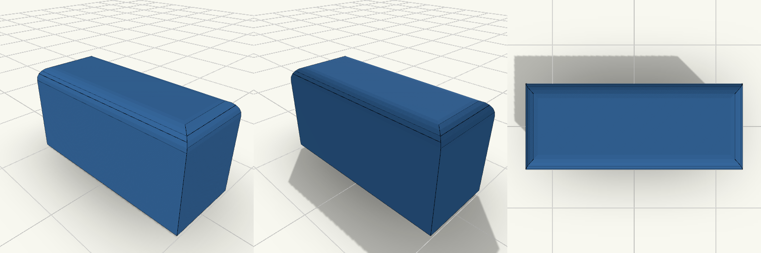
What it's for A solid rectangular crossfader knob for a DJ controller, with a centred socket underneath that fits over the fader stem. The socket's long side now runs across the knob width (Y). Dimensions Knob: 20 × 8 × 10 mm, top edges rounded 1.5 mm. Socket: 1.5 × 4.0 mm stem plus 0.1 mm clearance per side, 6 mm deep, with a small lead-in chamfer. The stem size is a placeholder; adjust stemw and stemt to match the real fader. Remix ideas Swap the socket for a D-shaped or round stem. Add grip ridges on the top face. Increase the height for a taller handle.
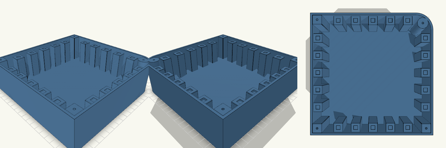
Arecson — Base con Pilares de Pulsador
Arecson es una base de caja de 180 × 180 × 50 mm con una sola esquina redondeada, pensada para un controlador DJ. Cuatro pilares de esquina, uno de ellos cilíndrico en la curva, permiten atornillar la tapa, y una fila de cinco pilares sostiene pulsadores de 6 mm. Características Caja de una pieza, sin tapa, con suelo plano. Pilares de esquina de 50 mm con guía de 3 mm y 30 mm de profundidad. Cinco pilares de 14 × 14 × 45 mm en fila horizontal en la zona inferior. Asiento de 6,1 mm y 2 mm de profundidad en cada pilar. Notas de impresión Si el pulsador entra justo, subir el asiento a 6,2 mm.
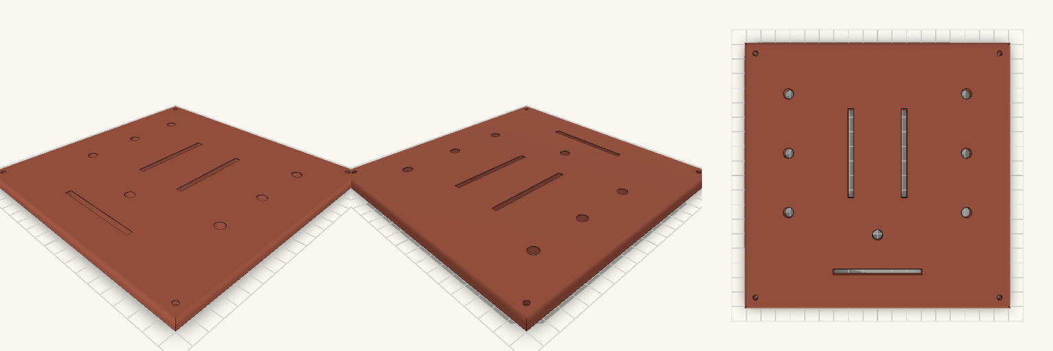
Tapa 180x180 con 3 crossfaders y 7 potenciómetros
Tapa de 180 × 180 × 5 mm para un controlador DJ, con tres ranuras de crossfader y siete agujeros de potenciómetro de 7 mm. Medidas a comprobar Ranuras de crossfader: 60 × 4 mm (el largo total del recorte según la ficha de tu modelo). Agujeros de potenciómetro: 7 mm, seis a ±60 mm en X y uno central en X = 0, Y = −40 mm. Cuatro tornillos M3 avellanados en las esquinas. No incluye Taladros de fijación de los crossfaders ni de los potenciómetros.