Three-Piece Monitor Top Shelf with Rear Legs
Created 4 days ago
Description
A three-section shelf that sits on the top edge of a 27-inch curved monitor and holds small items above the screen. The shelf follows a 1500R curve, so the ends sit about 32 mm further forward than the centre, and it measures about 620 mm wide by 100 mm deep when the sections are joined. Each section is sized to print on a 250 × 250 mm bed.
The shelf surface is a mesh of 11 mm square openings with 3 mm bars on a 14 mm pitch. An 8 mm solid rim runs around the outer edge, and the mesh stops short of the dovetail joints and leaves a solid pad under each leg's screw area. The sections are 12 mm thick.
The three sections join with sliding dovetails; slide them together from front to back. The joint has 0.3 mm clearance, giving a light push fit rather than a snap. The two rear legs are separate flat plates. Each leg drops 80 mm behind the monitor, presses against the back of the case, and fastens to the shelf with two M3×20 screws driven down from the top. The screw heads sit in recessed pockets and bite into 2.6 mm pilot holes in the leg tab.
Four M3×20 screws are included in the model, two per leg, shown seated in their pockets. Each has a 5.5 × 3 mm head with a hex socket and a 3 × 20 mm shaft. The shafts are plain, with no modelled thread, so they will not cut a real thread in printed plastic — print them lying on their sides, then ream or tap the pilot holes, or substitute metal M3 screws. Small printed screws are fragile, so print a spare.
- Three shelf sections, each fits a 250 × 250 mm print bed
- Assembled width about 620 mm; shelf depth about 100 mm
- 11 mm square mesh openings with 3 mm bars
- Sliding dovetail joints with 0.3 mm clearance
- Separate left and right rear legs, 80 mm drop
- Two M3×20 screws per leg, recessed from the top
- Four printable M3×20 screws with hex sockets included
- Print shelf sections flat on the bed; print legs lying on their backs; print screws on their sides
Dimensions are set for a 27-inch curved panel and are estimates rather than published monitor figures. The leg plates sit 51 mm behind the screen face, assuming a 40 mm monitor top. Measure your monitor's top edge and the gap to the back bulge before printing, and adjust if they differ.
Images
More like this
Explore more in Desk & Tech →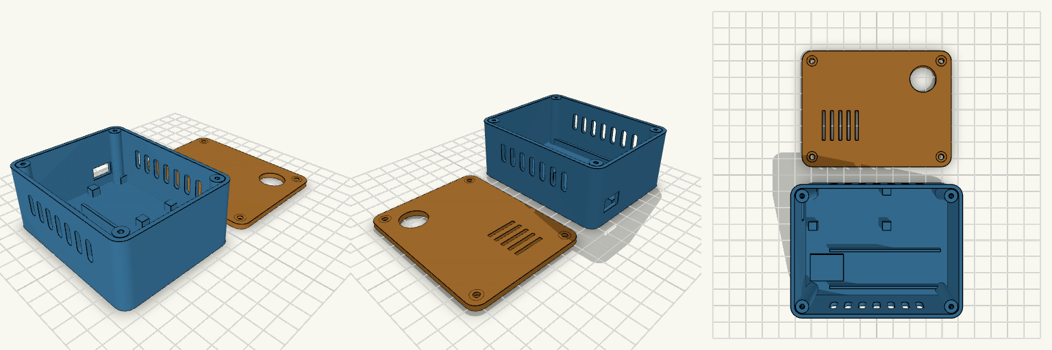
SilentSOS Two-Piece Electronics Enclosure
A 90 × 70 × 40 mm two-piece enclosure for an ESP8266 NodeMCU SOS alert device: a 37 mm tall base with 2 mm walls and a separate 3 mm lid, with 6 mm rounded vertical corners. The lid is printed flat and fastens with four M3 screws into corner bosses. Remix hooks Component mounting: no hole positions were guessed. The NodeMCU sits on four 5 mm locating pads at the board corners (49 × 26 mm area, nb, nbc). Once measured, add real standoffs in extraposts as [x, y] pairs and set post_pilot. Battery bay: two 1.5 mm rails 22 mm apart hold a cell of about 18 mm diameter, 65 mm long. Move or space them for other cells. DC-DC zone: a low 20 × 16 mm pad, free to move or resize. USB opening: 13 × 8 mm in the short wall, aligned to the NodeMCU position. SOS button: 16 mm hole in the lid (btnd, btnpos). Ventilation: seven slots in each long wall plus five slots in the lid. Screws: 2.6 mm pilots in the bosses, 3.4 mm countersunk lid holes. Pairs well with heat-set inserts in the bosses, or a gasket strip for a dust-resistant fit. Export base and lid as separate STLs by rendering each module alone.
Open-Frame PC Test Bench for 250 mm Beds
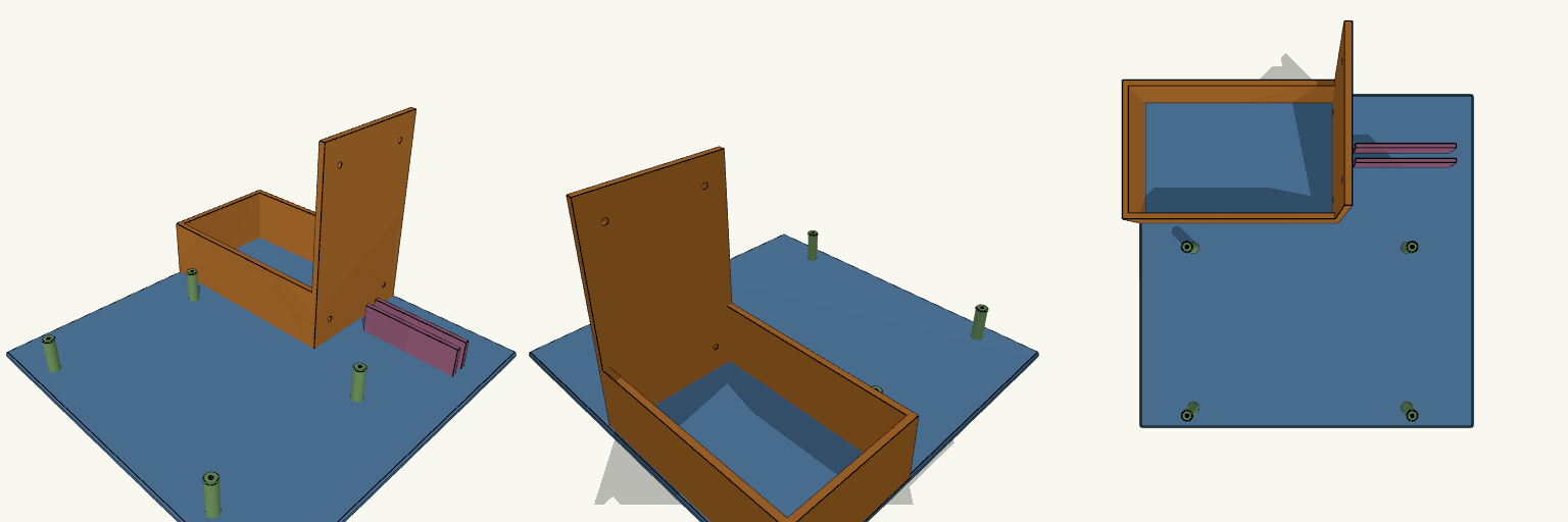
An open-frame PC test bench should stop the PSU, motherboard and SSD from shifting while you build; this one does it on a single 250 × 250 mm plate that fits a 256 × 256 mm printer bed. The base is 4 mm thick, and the whole bench prints as one piece in PLA. Fit and print numbers Base plate: 250 × 250 × 4 mm; one-piece print. PSU socket: 140.4 × 86.4 mm pocket with 4 mm walls on three sides; rear bracket 150 mm tall with four ATX screw holes at 64 × 114 mm spacing, 4.2 mm diameter. Motherboard: four 25 mm-high standoffs with 2.8 mm pilot holes for M3, spaced 160 × 120 mm. This is not the standard mATX hole pattern, so check it against your board first; a full mATX board will overhang the plate. SSD: 72 mm-long slot with two 3 mm walls, 22 mm high, holds a 7 mm-thick 2.5-inch drive on its edge. The layout is a compromise for a 250 mm bed: the PSU and board both need room, so the standoff spacing is fixed at 160 × 120 mm rather than a true mATX pattern. Print it in PLA if you want the base stiff without extra parts.
Pokéball Keyboard Wall Shelf
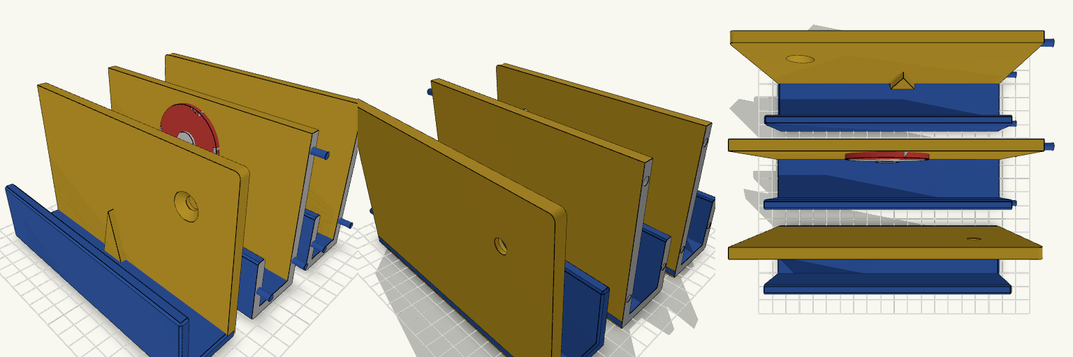
A Pokéball-badged wall shelf that cradles a full-size keyboard behind a tall front lip. Red-and-white emblem, yellow back panel, blue ledge: the Kanto starter-kit palette on a desk wall. The shelf prints as three 160 mm sections laid out together on the plate, ready to glue into one 480 mm piece. Three sections joined with 4 mm alignment pegs and sockets 40 mm front lip keeps the keyboard in place Two 8 mm countersunk screw holes at the ends for wall mounting Sections footprint about 168 x 40 mm each
Info Orbs 1.28in Five-Display Case
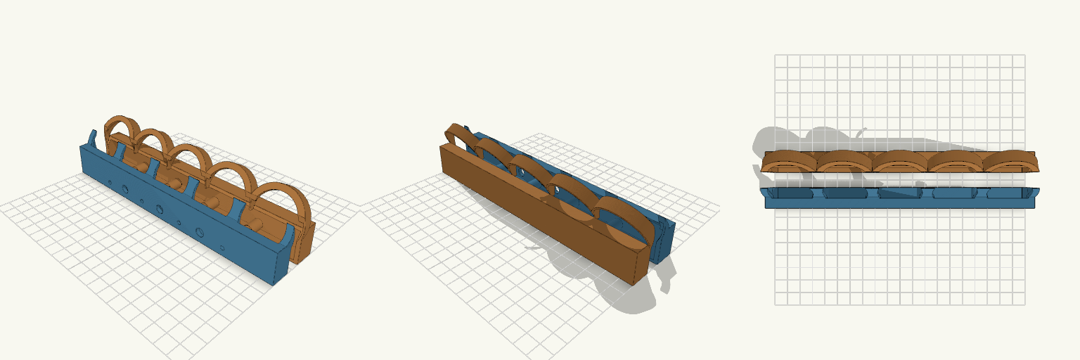
Two-part case for an Info Orbs build: five 1.28in round TFT displays across the top, a hollow base for a 200 mm controller board, and three push buttons in the front wall. The Front Half and Back Half join with four M3 screws running front to back, with heat-set inserts in the back half. Both halves print flat on their cut faces. What it fits Five 1.28in round TFT displays on 40 mm centres, tilted back 30°, with 42 mm outer housings, 39.5 mm PCB pockets and 33 mm windows. The scalloped top edge follows the rims of the displays instead of running as a plain box. A 200 mm board, including a large Arduino section. Interior space is 196 × 24 × 35 mm, so there is about 3 mm of slack all round the board. Three 6 mm tact-switch caps in 7 mm front-wall holes at −40, 0 and +40 mm. Four M3 screws at x = −10, 25, 60 and 92 mm: 3.4 mm clearance holes in the front half, 4.2 mm heat-insert holes 9 mm deep in the back half. Check before printing The screw positions assume the Arduino's 15–70 mm span is measured from the left (−X) end of the board, which puts it at x = −85 to −30 mm and keeps the nearest screw about 20 mm clear. If that span is measured from the right end, mirror the screw holes before printing. The screw bosses sit at floor level and run front to back, so they pass under the board — confirm the board clears them. The outside measures 200 × 30 × 40 mm with 3 mm walls and floor. That is not 200 × 30 × 25 mm as first specified, so check your electronics against the larger figure. Known limitations There is no internal switch mount. The tact switches must be glued or wired in place. The button holes suit 6 mm tact-switch caps, not 12 mm panel-mount buttons.
Bakelite-Era Two-Piece Electronics Enclosure
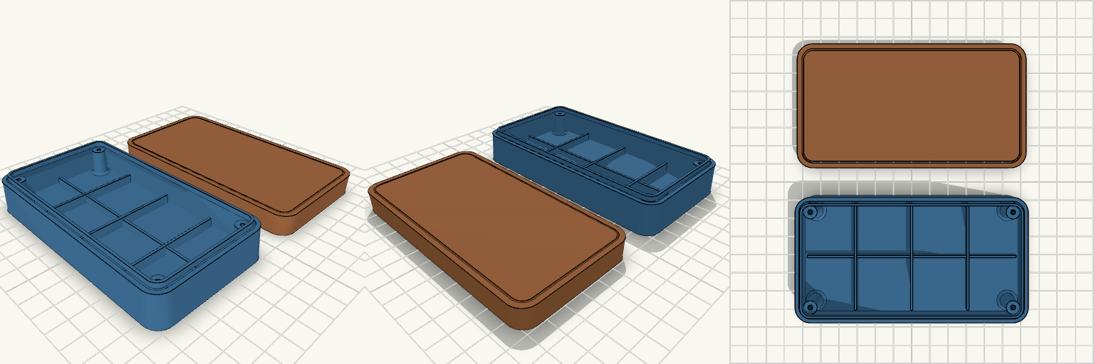
A compact two-piece case with a vintage Bakelite silhouette: rounded corners, softly drafted walls, and a clean split line between the lower housing and the upper cover. At 120 × 65 × 28 mm, it gives a small board or module a protected home, with a hollow internal cavity, four corner screw bosses, reinforcement ribs, and a tongue-and-groove closing lip. The enclosure prints as two separate pieces, with the cover laid beside the housing so both print without supports. Design notes Lower Housing: the deeper shell, with corner bosses, internal ribs, and a raised closing tongue. Upper Cover: the lid, with a matching groove and clearance holes for the screws. Walls and corners: 2 mm walls, 8 mm outer corner radius, and a 1.5° draft on the outer shell and lip. Screw bosses: four corner bosses with 2.6 mm pilot holes in the housing and 3.2 mm clearance holes in the cover. Printing: separate upper and lower parts, oriented to avoid supports.
Octobay — 5.25" to 3.5" Drive Cage
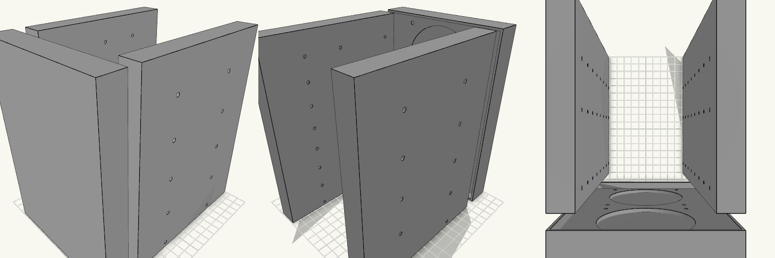
Octobay turns a five-bay stack of half-height 5.25" slots into room for eight 3.5" drives, and adds a 25 mm front cage that carries two 92 mm fans. The outer side faces take M3 heat-set inserts, so the whole cage screws into the case's 5.25" rails instead of resting on them. Everything is one printed part: the drive stack, the side mounting blocks and the fan cage print as a single body. Because the fans close off the front, drives now load from the back. The fan cavity behind the grille is hollow, so air still passes through to the drive stack. Dimensions Overall: 145 mm wide × 197.5 mm deep × 205.5 mm tall Fits: five half-height 5.25" bays Holds: eight 3.5" drives, stacked vertically Drive channel: 102.6 mm wide — 1 mm of play around a 101.6 mm drive Mounting 20 insert holes, 10 per side, for M3 heat-set inserts — 4.2 mm across and 6 mm deep Two insert holes per bay, at 41.3 and 117.5 mm from the front, 6.35 mm above each bay floor Solid blocks sit behind each hole to give the inserts something to bite into Three M3 screw holes per side per drive, at 14, 76.6 and 117.6 mm from the front Cross ribs sit clear of the screw holes so a screwdriver can reach every fastener Fan cage Two 92 mm fans, stacked vertically on the 25 mm front section 88 mm fan openings with 4.4 mm screw holes on the standard 82.5 mm square pattern Hollow cavity behind the fans feeds air to the drive channels Print notes Drive channels are open at the back, top and bottom, and the gaps between the inner and outer side walls are open for cable routing. Screw and insert positions and the 205.5 mm height follow common 5.25" bay standards; they have not been checked against a specific case, so measure your bay rails and drives before printing.