TroughTrek — Modular Escape Ramp
Created 1 months ago
Description
A modular wildlife escape ramp built to saddle the rim of a 150-gallon stock tank. Designed to hang tight against the straight section of the wall, it leaves the center of the trough wide open while providing a secure path out of the water.
Features
- Modular Assembly: Print the sections flat and slot them together using the flush integrated joints.
- Safe Traction: Half-cylinder ribs spaced evenly along the ramp offer grip without sharp edges that could catch paws or hooves.
- Dual Path: Includes both an inner descent into the water and an optional exterior ramp leading down to the ground.
- Rim Saddle: The central mount is contoured to slot cleanly over a standard 40mm rolled trough rim.
Dimensions
- Width: 150mm (approx 6 inches)
- Incline: 35 degrees
- Segment Length: 300mm per section, yielding a ~344mm vertical drop per side (well below the typical waterline).
Images
More like this
Explore more in Home & Fixtures →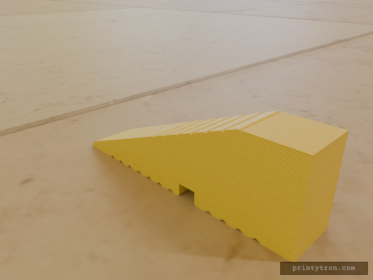
Doorstop Wedge Rib Clip
A doorstop wedge with the low, hard-working profile of a chalk wedge, cut to a 10 mm width to grip the raised PVC rib on a balcony door sill. The underside carries a straight snap-fit groove that presses over the rib, the thin tip lets the door glide across, and the block behind it stops the door dead so it cannot swing open while you are out on the balcony. The top rises from a 1 mm tip to a flat 16 mm shelf — the ramp reaches that height about 39.5 mm back from the tip and then runs flat to the fat end. Both the top and bottom faces carry shallow V-ribs across the width: grip where a hand or a door meets the wedge, and a lightly textured finish underneath. Design notes 50 × 10 mm footprint with a 16 mm flat top; the ramp climbs from a 1 mm tip to the shelf, and the shelf’s front edge is left sharp Bottom groove 3.6 mm wide (3.4 mm rib plus 0.2 mm clearance) and 2.5 mm deep, flat-bottomed with a 0.3 mm entry chamfer, centred 20 mm back from the fat end V-ribs run 3 mm apart at 0.4 mm deep; bottom ribs start about 8 mm from the tip and stop clear of the groove so its edges stay clean, while top ribs begin where the wedge is thick enough to cut into 0.5 mm chamfers along the top edges, and a 1 mm 45° bevel at the tip to help the door ride over Printing Print flat on the bottom face with the groove facing down, in PETG at 0.2 mm layers, 4 walls and 40% infill.
Fly Screen Frame Snap Lock for Wall Gap
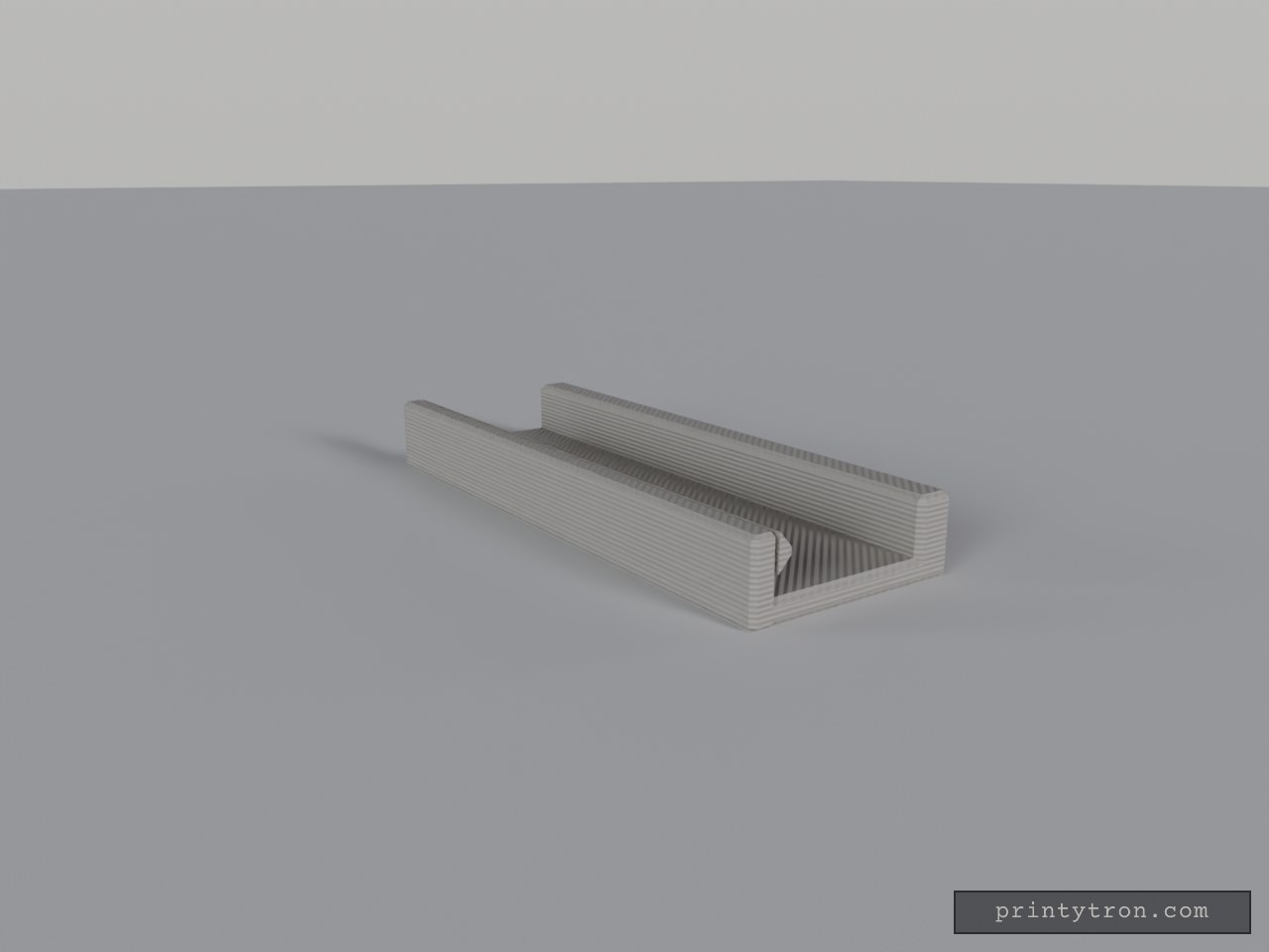
A fly-screen frame that keeps popping out of the gap between it and the wall is the annoyance; this clip holds it in line without screws. The frame slides in along the channel from either end, past ramps on a thin flexible arm — it gives way to a deliberate pull but stays put in a gust — and the back carries a glue strip so the clip sits flat against the wall. Fit and hold Channel: 10.2 mm wide for a 1 cm frame, 0.2 mm clearance. Entry: open at both ends, so the frame slides in along the 40 mm length; the arm's lip is ramped down at both ends to start it easily. Front arm: 1.6 mm thick and flexible, fixed only along its base, so the frame opens up easily and still holds in wind. Back wall: rigid, no lip — it stays clear of the sliding frame and only the arm does the holding. Glue recess: 0.8 mm deep and 30 mm long on the back, so the glue strip sits flush and the clip lies flat. Size: 40 × 14.3 × 5 mm, matching the 0.5 cm gap between wall and frame. Use PETG for the flexing front arm — it takes the repeated opening and closing better than a brittle filament, and the stiffness of the arm is what decides whether the frame holds or rattles loose.
Perilla de estufa de repuesto con vástago reforzado
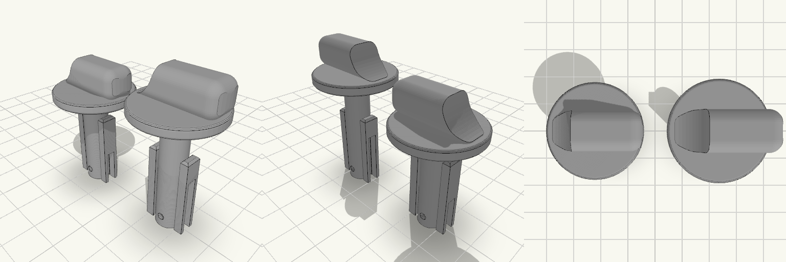
La perilla de la estufa que gira en falso o se parte deja el fuego sin control; esta perilla de repuesto se calza sobre el caño de gas y se traba con pasador, con el pulgar recortado al contorno del collar y todos los bordes del agarre redondeados para girar sin engancharse. La placa trae dos perillas: la original y una copia con vástago de 35 mm para cambiar el largo según la estufa. Cotas que deciden el calce Dos perillas en la misma placa: la original mide 41,5 mm de alto total (12 mm de cabeza + 29,5 mm de vástago); la copia mide 47 mm de alto total (12 mm de cabeza + 35 mm de vástago). En la placa ocupan 58 × 26 × 47 mm. Vástago: 8 mm de diámetro exterior, con dos aletas planas de refuerzo de 24 mm a los lados; en la copia, las aletas quedan en la zona de la punta. Vástago hueco: orificio de 5,5 mm de diámetro, abierto en la punta. En la original llega a 26 mm de profundidad y queda ciego en los últimos 3,5 mm hacia la cabeza, con paredes de aproximadamente 1,25 mm; la copia mantiene el mismo orificio de 5,5 mm. Agujero pasante: 2,2 mm de diámetro, horizontal, con el centro a 3,5 mm del extremo inferior; cruza la cavidad del vástago, así que la chaveta atraviesa el caño de gas. Endija: 3 mm de ancho, abierta en la punta; va a 90° del agujero del pasador, atraviesa el vástago y corta también las aletas laterales, dejando el extremo dividido en dos mitades flexibles. En la original llega a 11 mm; en la copia llega a 17,5 mm, la mitad de su vástago. Cabeza: collar de 26 mm de diámetro por 3 mm de alto; el pulgar mide 26 mm de ancho, 10 mm de grosor y 9 mm de alto sobre el collar, ya no pasa el contorno del collar, es plano de un lado y baja curvo del otro. Todas las aristas del pulgar tienen 3 mm de radio; los bordes del collar tienen 0,8 mm. Cada perilla se imprime de una sola pieza; la endija no separa el modelo, solo deja flexibles las dos mitades del extremo. El acabado negro mate sale del filamento que elijas, no de la geometría. Antes de imprimir, mide el diámetro del caño de gas y el del pasador: el hueco del vástago y el agujero pasante son las dos cotas que no perdonan, y si no coinciden es mejor ajustarlas antes de gastar material.
T-Post Cap With 3-Inch Round Platform
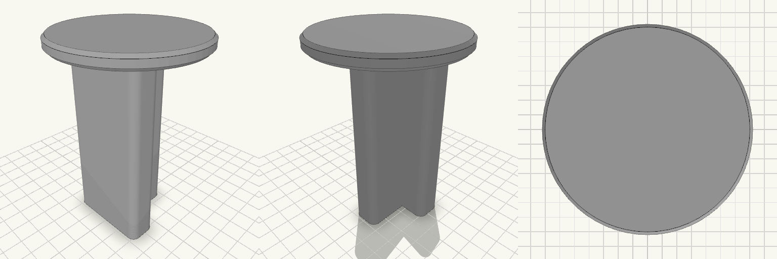
A slip-on cap for a steel T-post: 4 in tall, with a T-shaped socket that drops over the post and a 3 in round platform, 1/4 in thick, on top. Fits Steel T-posts, matched to the T-socket below. The socket is a T: a 36 mm crossbar, 7 mm wide at the stem entry, with a 7 × 30 mm stem running down, and a 4 mm wall following that T all the way around. Takes the place of a plain post cap and adds a flat, 3 in round surface on top of the post. Check before printing The socket is the whole fit, and its numbers are a starting size, not a standard — T-posts differ in flange width and web thickness between manufacturers and post weights. Measure the post you intend to use across the crossbar, across the stem, and across the full depth, then set the socket to those sizes plus a little clearance for paint and burrs before you commit filament. Nothing else on the part affects fitment. Does not fit Round posts, wooden 4x4 posts, or any post without a T cross-section. T-posts whose crossbar or stem is wider than the socket above — T-post profiles are not interchangeable, so do not assume a fit from the post name or the post weight alone. The cap prints as a single piece, 76 × 76 × 102 mm overall.
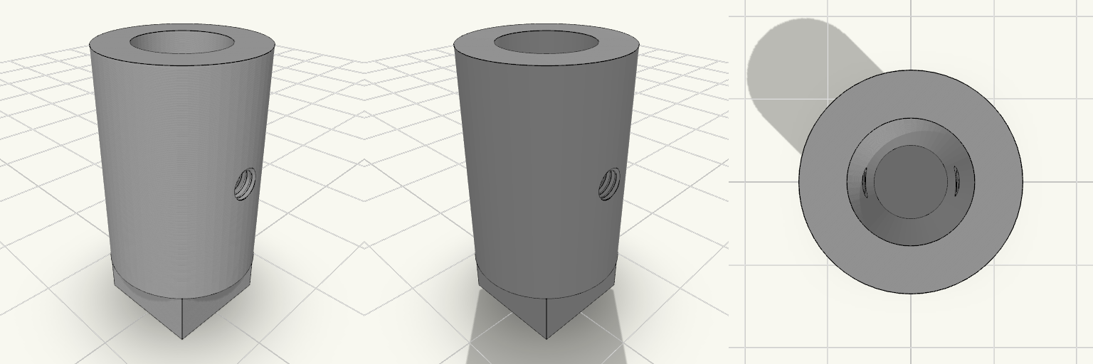
Barra cilíndrica con base cuadrada sólida
Para qué sirve Es una barra cilíndrica vertical de Ø14 mm sobre una base cuadrada maciza de 10 × 10 mm. La base y la barra comparten eje, y el agujero central de Ø8 mm empieza justo encima de la base: la base queda cerrada por abajo. Sirve como separador, pie de apoyo o guía para un vástago o tornillo que entre por arriba. A media altura de la barra hay dos agujeros laterales roscados M3, diametralmente opuestos, que llegan hasta el agujero central. Cada rosca permite enroscar un tornillo M3, uno por lado, para fijar lo que se introduzca en el agujero central o para sujetar la barra a otra pieza. La barra es más ancha que la base y sobresale 2 mm por cada lado. Dimensiones Barra: Ø14 mm exterior, con 20 mm de altura sobre la base. Agujero central: Ø8 mm, concéntrico, solo en la barra (no atraviesa la base). Agujeros laterales: dos roscados M3 de paso 0,5 mm, opuestos, a 15 mm de altura (mitad de la barra), pasantes hasta el agujero central. Base: cuadrada de 10 × 10 mm, sólida, con 5 mm de espesor. Altura total: 25 mm. Pared entre el agujero central y el exterior de la barra: 3 mm por lado. Tamaño en la cama: 14 × 14 × 25 mm. Notas de impresión La base plana de 10 × 10 mm se apoya directamente en la cama. La barra sobresale 2 mm por cada lado sobre la base; ese pequeño vuelo suele imprimirse sin soportes con buena refrigeración. Conviene imprimirla en vertical, tal como está orientada, para que el agujero central quede limpio y sin escalones. El fondo cerrado del agujero actúa como tope: un vástago introducido desde arriba no sobresale por debajo. Los tornillos M3 que se enrosquen en los laterales no deben pasar de unos 6 mm de rosca: con la pared de 3 mm, la punta queda dentro del agujero central sin tocar la pared opuesta. Las roscas M3 impresas pueden salir justas; después de imprimir, conviene pasar un macho de M3 por cada agujero lateral para limpiarlas. La base es más pequeña que la barra: si se necesita más superficie de apoyo o de pegado, conviene ampliarla. Ideas de remezcla Ampliar la base cuadrada a 14 × 14 mm o más para igualarla con el diámetro de la barra y ganar estabilidad. Alargar el tramo de barra por encima de la base para adaptarlo a la altura que necesites. Cambiar el diámetro del agujero central o el tamaño de las roscas laterales para que encajen un tornillo o un tubo concretos. Añadir un chaflán o un radio en el borde superior de la barra para facilitar la entrada de un vástago.
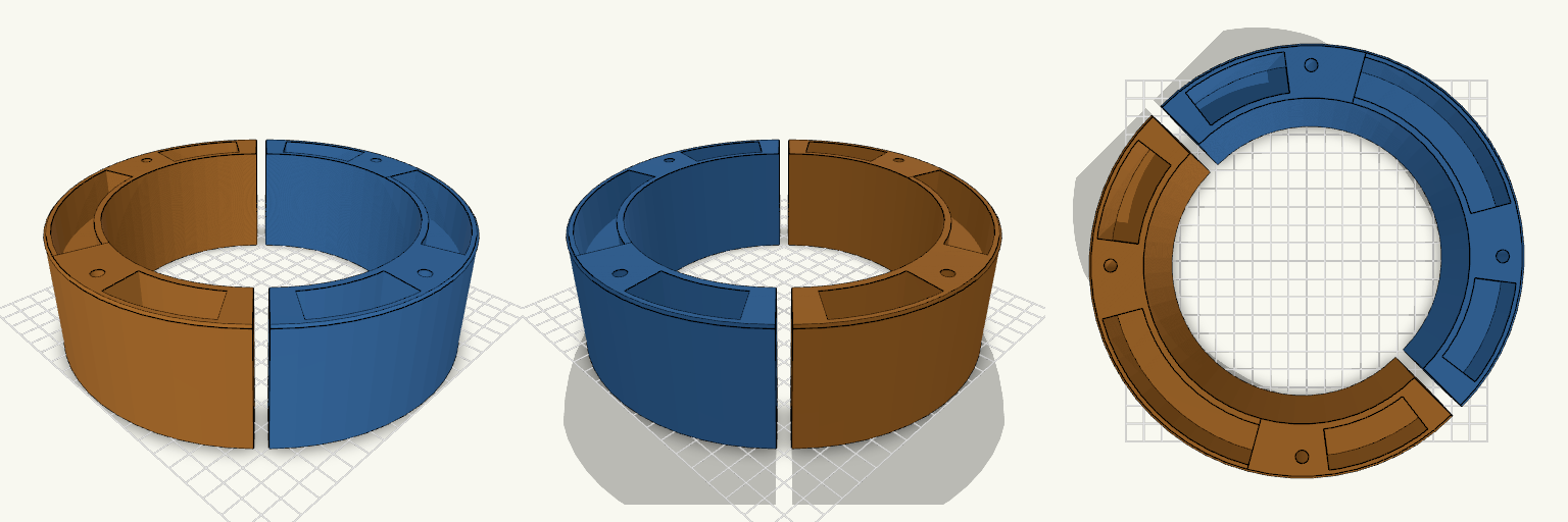
Rondella Ø195/Ø145 mm in due metà
Rondella in due semianelli, Ø195 mm esterno, Ø145 mm interno, altezza 60 mm, con quattro fori Ø6 mm su circonferenza Ø175 mm. Le tasche di alleggerimento sono ricavate solo sulla faccia superiore; la faccia inferiore resta piana. Tasche: 2 archi da 60° e 4 archi da 30°, profondità 22 mm Anima inferiore piena: 38 mm Pareti interna ed esterna: 3 mm Taglio a 45° rispetto ai fori: ogni metà ha due fori interi Stampa senza supporti, con la faccia inferiore sul piano