3D-printable home fixtures & hardware
Brackets, cabinet pulls, knobs, doorstops, racks and mounts built to real measurements. Browse what makers built, or describe the exact fixture you need and Printy makes it.
Need one that fits your exact measurements? Start building →
Newest
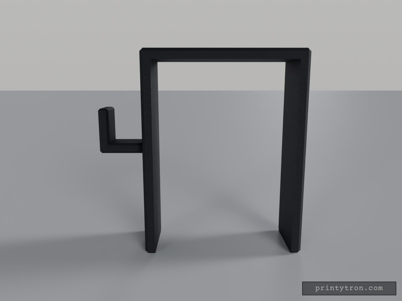
Beam Clamp Clothes Hanger with Side Hook
What it's for A saddle that drops over the top of a support beam and turns it into a place to hang clothes. The inverted U-shaped channel grips the beam from above, and a hook projects from one side with an upturned tip so hangers and garments stay put. Beam Saddle — the U-shaped body that slides down over the beam Hook — the side arm with an upward tip for hangers or coats, set at mid-height of the saddle Both areas print as a single piece; nothing needs assembling. Dimensions Saddle opening: 68 mm inner width, sized for a beam of that width Overall saddle: 78 × 30 mm footprint, 100 mm tall Channel: 95 mm deep, with 5 mm thick walls Hook: 22 × 15 × 22 mm, mounted at mid-height so its tip stays inside the 100 mm envelope The 95 mm channel is generous for a shallow beam — the saddle simply sits lower on it, and the hook rides down with it. Print notes Print the saddle opening facing up so the channel needs no supports A few extra perimeters on the hook help when it carries heavy coats Scale the opening slightly if your beam measures over 68 mm Remix ideas Lengthen the hook for bulky winter coats Shorten the legs for a shallower beam and keep the height with a taller top plate Add a second hook on the opposite side for more hanging room Add a small lip or screw hole at the bottom of the saddle to stop it shifting sideways
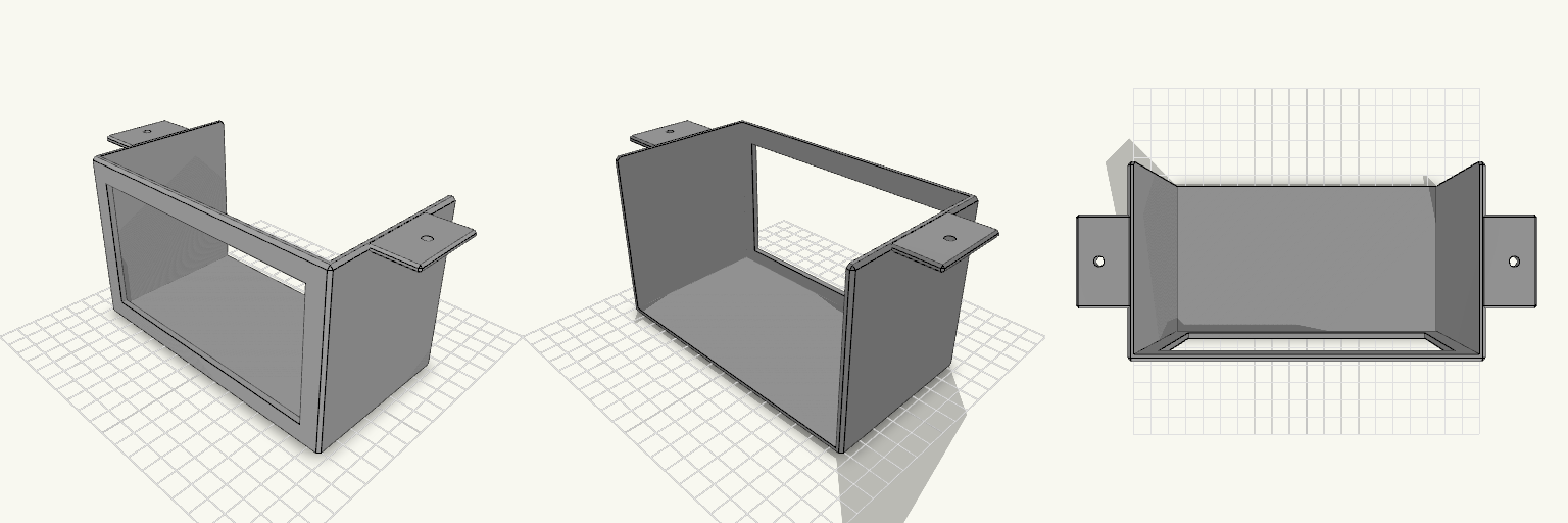
Unterbauhalterung für Echo Show 5 mit offener Rückseite
Die Halterung ist eine Schale für den Echo Show 5, die unter einen Schrank geschraubt wird. Die Rückseite bleibt offen, sodass das Kabel austreten kann; vorn sitzt ein Ausschnitt für das Display. Zwei seitliche Laschen mit je einem 4,5-mm-Loch nehmen die Befestigungsschrauben auf. Die Innenmaße liegen bei 148,6 mm Breite und 90 mm Höhe – bei 148 mm Gerätebreite bleibt so rund 0,3 mm Spiel je Seite. Im Ganzen misst die Halterung 198,6 × 86 × 93 mm, wobei die 86 mm Tiefe den Platzbedarf unter dem Schrank bestimmen. Der Rahmen um das Display ist oben und unten gleich breit: Der obere Rand misst 11 mm (3 mm Boden plus 8 mm Steg), genau wie der untere; der Display-Ausschnitt ist entsprechend oben 5 mm niedriger gehalten. Die Maße sind am Gerät nicht nachgemessen – vor dem Druck die Innenmaße am eigenen Echo Show 5 prüfen. Remix-Hooks Innenbreite: 148,6 mm bei 148 mm Gerätebreite ist bewusst eng gewählt; wer mehr Luft zum Einlegen will, geht auf 150 mm zurück und erhält etwa 1 mm Spiel je Seite. Innenhöhe: 90 mm sind der zweite echte Freiheitsgrad – mehr Höhe schützt das Gerät besser, weniger macht die Schale flacher unter dem Schrank. Tiefe: Die 86 mm Gesamttiefe (rund 80 mm innen) sind die knappste Stelle; eine flachere Schale passt unter niedrige Schrankböden. Displayausschnitt: Der obere Rand ist auf 11 mm gesetzt und entspricht dem unteren; wer mehr Sichtfläche will, kann den oberen Rand schmaler machen, muss dann aber die Rahmenstabilität prüfen. Schraublaschen: Die 4,5-mm-Löcher und ihr Abstand passen sich vorhandenen Schrauben oder einer Bohrschablone an; sie wandern mit der Höhe nach oben mit. Kabelauslass: Die offene Rückseite kann breiter werden oder eine zusätzliche Kabelklemme bekommen. Befestigung: Statt der Laschen ist eine Variante mit Klebefläche oder Klemme denkbar. Als Basis passt die Halterung unter Küchen- oder Regalschränke; Kabelclips und passende Holzschrauben ergänzen sie.
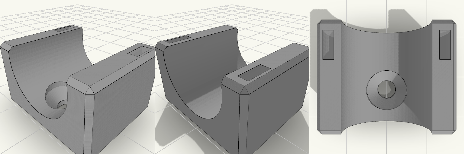
Industrial Saddle Wall-Mount Air-Hose Clip
A plain block with a channel across its top and a single hole sunk into the floor of that channel — drive a drywall screw through it, drop the 5/8″ OD air hose in, and the fixing disappears beneath the hose. A slot cuts through the other half of the block, so a zip tie loops down over the hose and cinches it without ever crossing the screw. No side tabs, no bracket ears, nothing protruding past the saddle: a small, purely functional piece of wall hardware with a squared-off, industrial silhouette. Design notes Top channel sized for 5/8″ OD air hose, with a little clearance. Countersunk screw hole sits in the channel floor with a 9 mm countersink, wide enough for a typical drywall screw head and hidden once the hose is seated. Zip tie slot is offset to the far half of the block, clear of the screw area; takes a common tie up to about 5 mm wide. Load order matters: drive the screw first, then lay the hose in and tension the tie. With a single fastener the block can spin before the hose is loaded — snug the screw down before fitting the hose so it stays square to the wall. Block is 20 mm long, 24.3 × 20 × 14.1 mm overall as it sits on the build plate. Prints as a single body; screws and zip ties are separate hardware.
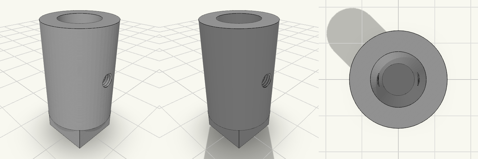
Barra cilíndrica con base cuadrada sólida
Para qué sirve Es una barra cilíndrica vertical de Ø14 mm sobre una base cuadrada maciza de 10 × 10 mm. La base y la barra comparten eje, y el agujero central de Ø8 mm empieza justo encima de la base: la base queda cerrada por abajo. Sirve como separador, pie de apoyo o guía para un vástago o tornillo que entre por arriba. A media altura de la barra hay dos agujeros laterales roscados M3, diametralmente opuestos, que llegan hasta el agujero central. Cada rosca permite enroscar un tornillo M3, uno por lado, para fijar lo que se introduzca en el agujero central o para sujetar la barra a otra pieza. La barra es más ancha que la base y sobresale 2 mm por cada lado. Dimensiones Barra: Ø14 mm exterior, con 20 mm de altura sobre la base. Agujero central: Ø8 mm, concéntrico, solo en la barra (no atraviesa la base). Agujeros laterales: dos roscados M3 de paso 0,5 mm, opuestos, a 15 mm de altura (mitad de la barra), pasantes hasta el agujero central. Base: cuadrada de 10 × 10 mm, sólida, con 5 mm de espesor. Altura total: 25 mm. Pared entre el agujero central y el exterior de la barra: 3 mm por lado. Tamaño en la cama: 14 × 14 × 25 mm. Notas de impresión La base plana de 10 × 10 mm se apoya directamente en la cama. La barra sobresale 2 mm por cada lado sobre la base; ese pequeño vuelo suele imprimirse sin soportes con buena refrigeración. Conviene imprimirla en vertical, tal como está orientada, para que el agujero central quede limpio y sin escalones. El fondo cerrado del agujero actúa como tope: un vástago introducido desde arriba no sobresale por debajo. Los tornillos M3 que se enrosquen en los laterales no deben pasar de unos 6 mm de rosca: con la pared de 3 mm, la punta queda dentro del agujero central sin tocar la pared opuesta. Las roscas M3 impresas pueden salir justas; después de imprimir, conviene pasar un macho de M3 por cada agujero lateral para limpiarlas. La base es más pequeña que la barra: si se necesita más superficie de apoyo o de pegado, conviene ampliarla. Ideas de remezcla Ampliar la base cuadrada a 14 × 14 mm o más para igualarla con el diámetro de la barra y ganar estabilidad. Alargar el tramo de barra por encima de la base para adaptarlo a la altura que necesites. Cambiar el diámetro del agujero central o el tamaño de las roscas laterales para que encajen un tornillo o un tubo concretos. Añadir un chaflán o un radio en el borde superior de la barra para facilitar la entrada de un vástago.
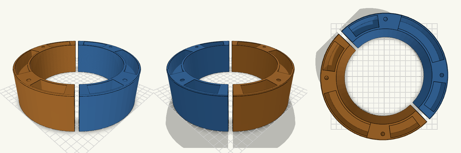
Rondella Ø195/Ø145 mm in due metà
Rondella in due semianelli, Ø195 mm esterno, Ø145 mm interno, altezza 60 mm, con quattro fori Ø6 mm su circonferenza Ø175 mm. Le tasche di alleggerimento sono ricavate solo sulla faccia superiore; la faccia inferiore resta piana. Tasche: 2 archi da 60° e 4 archi da 30°, profondità 22 mm Anima inferiore piena: 38 mm Pareti interna ed esterna: 3 mm Taglio a 45° rispetto ai fori: ogni metà ha due fori interi Stampa senza supporti, con la faccia inferiore sul piano
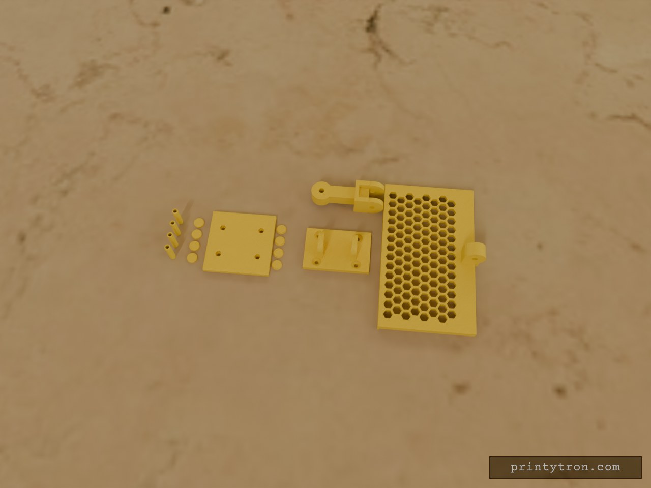
Schwenk- und neigbare Wandhalterung für Marshall Acton 2
Die schwenk- und neigbare Halterung trägt einen Marshall Acton 2 (260 × 160 × 150 mm, ca. 3 kg) an der Wand oder – mit der Konterplatte – an einem Regalbrett. Sie besteht aus Wandplatte, Schwenkglied, Auflage, vier Schraubenkappen, der Konterplatte, vier Mutternkappen und vier Hülsen. Das Schwenkglied dreht um eine senkrechte M8-Schraube, die Auflage um eine waagrechte M8-Schraube; in der Grundstellung steht die Auflage 20° nach unten geneigt, die 45°-Drehung stellst du an der Schwenkachse ein. Das Gelenk ist verlängert, die Gesamttiefe liegt bei etwa 247 mm. Die Teile werden einzeln gedruckt und montiert. Wandplatte: 66 × 100 mm Auflagefläche, 8 mm dick, mit vier außen angesenkten Löchern Ø 5,5 mm bei ±22 mm seitlich und ±30 mm in der Höhe. Um jedes Loch sitzt eine Vertiefung für eine Kappe; nach vorn stehen zwei Gabelohren für das Schwenkglied. In der Drucklage misst sie etwa 66 × 100 × 44 mm. Schwenkglied: sitzt zwischen den Gabelohren und dreht um eine senkrechte M8-Schraube; am vorderen Ende hat es die zweite Gabel für die Neigeachse. In der Drucklage misst es etwa 37 × 114 × 36 mm. Auflage: 236 × 140 mm, 6 mm dick, mit 9 mm hohen Kanten seitlich und vorn; sie ist 20° nach unten geneigt und nimmt den Lautsprecher auf. Die Platte ist mit Sechskant-Aussparungen von Ø 14 mm und etwa 3 mm Stegbreite durchbrochen, um Filament zu sparen. Rand, Kanten und die Stelle über dem Steg bleiben geschlossen. Der Lautsprecher liegt auf den Stegen; ein Gummistreifen oder eine Antirutschmatte darauf verhindert Rutschen und Kratzer. In der Drucklage misst sie etwa 236 × 151 × 51 mm. Schraubenkappen: vier Stück, Kragen Ø 16 mm mit abgeschrägter Kante, Stopfen Ø 14 mm. Die Vertiefung in der Wandplatte hat Ø 14,4 mm und 3 mm Tiefe; mit einem Tropfen Sekunden- oder Heißkleber halten die Kappen fest. Die vier Kappen messen in der Drucklage zusammen etwa 76 × 16 × 3,4 mm. Konterplatte: 100 × 100 mm, 8 mm dick, mit denselben vier Löchern wie die Wandplatte. Jedes Loch hat eine offene Sechskanttasche für eine M5-Mutter (SW 8), etwa 4,5 mm tief. Die Muttern werden von außen eingelegt; drucke die Platte mit der Taschenseite nach oben. Mutternkappen: vier Stück, Ø 16 mm, 4 mm hoch, mit abgeschrägter Kante. Auf der Unterseite sitzt ein Hohlraum mit Ø 10 mm und 2,8 mm Tiefe; darin verschwinden Mutter und überstehendes Schraubenende. Sie liegen über den Sechskanttaschen der Konterplatte und werden mit einem Tropfen Kleber gesichert. Drucke sie mit der Hohlraumseite nach oben, dann brauchen sie keine Stützen. Die vier Kappen messen in der Drucklage zusammen etwa 76 × 16 × 4 mm. Hülsen: vier Stück, 37 mm lang, Außen-Ø 9 mm, Innen-Ø 5,7 mm, leicht gefast. Sie werden durch Bohrungen im Regalbrett geschoben; das Brett braucht dafür Bohrungen von mindestens 9,5 mm. Die 5,5-mm-Löcher der Wandplatte sind für die Hülsen zu klein, sie sitzen nur im Regalbrett. Bei einem 37,12 mm dicken Brett kürzt du die Hülsen auf etwa 36,5 mm, sonst klemmen sie zwischen den Platten. In der Drucklage messen die vier Hülsen zusammen etwa 69 × 9 × 37 mm. Für die Montage an einem Regalbrett kommen Wandplatte und Konterplatte auf die beiden Seiten des Bretts. Die Schrauben gehen durch Brett und Hülsen; M5-Maschinenschrauben mit Gewinde bis unter den Kopf sind die richtige Wahl. Die Länge ist 8 mm Wandplatte + Brettstärke + 8 mm Konterplatte: bei einem 19-mm-Brett M5 × 40 mm, bei 25 mm M5 × 50 mm, bei 37,12 mm M5 × 60 mm. Die Schraube sollte ein Stück über die Mutter hinausragen; Unterlegscheiben sind nicht nötig. Für eine reine Wandmontage braucht die Wandplatte passende Senkkopfschrauben und zum Untergrund passende Dübel. Die Gelenke werden mit M8 × 70 mm für die Schwenkachse und M8 × 60 mm für die Neigeachse plus Nylonmuttern montiert; durch Anziehen klemmen sie. Die Klemmung hält über Reibung und kann bei Dauerlast nachgeben, deshalb gut anziehen und bei Bedarf Gummischeiben ergänzen. Für den Druck: PETG mit 5 Wandlinien und 40–50 % Füllung, bei der Wandplatte eher 60 %. Die Wandplatte flach auf die Rückseite legen, das Schwenkglied flach drucken; die Schraubenkappen mit dem Kragen nach unten, die Mutternkappen mit dem Hohlraum nach oben und die Hülsen aufrecht mit 100 % Füllung stützenfrei drucken. Die Auflage hängt schräg und braucht Stützen; die waagrechten M8-Bohrungen mit Stützen oder sauberem Nachbohren auf Ø 8 mm absichern. Jedes Teil für sich passt auf ein Druckbett von 256 × 256 mm, alle Teile zusammen nicht – verteile sie auf mehrere Druckplatten. PETG kriecht unter Dauerlast, direkte Sonne und Heizungswärme deshalb meiden. Die Tragfähigkeit bestimmen Wand, Regalbrett und Befestigung, nicht der Kunststoff.
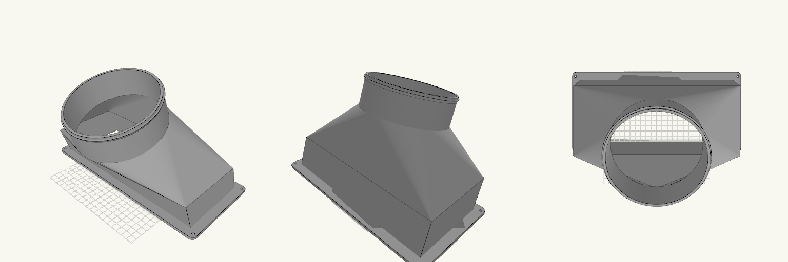
Klarstein DryFy 50L 150 mm Exhaust Adapter
Rectangular-to-round exhaust adapter for routing a 150 mm vent hose from a Klarstein DryFy Connect 50L dehumidifier. The part bolts over the unit's 285 × 120 mm rectangular exhaust port and rises through a 50 mm straight rectangular section before lofting to a round spigot that slides inside a 150 mm hose. The rectangular body leans 20° toward -Y, and the spigot carries a further 20° tilt in the same direction, so the hose leaves the unit well off vertical. The rear of the spigot is pulled back into line with the rear wall of the leaning body, so the back of the adapter is one straight, continuous face with no bulge or kink at the transition; the front still curves as the rectangle narrows to the round spigot. The flange sits flat on the print plate; the overhanging body and spigot will need support. Specifications Overall size: 315 × 220.9 × 186.3 mm as it sits on the print plate Mounting flange: 315 × 150 mm, 4 mm thick, sized to cover a 285 × 120 mm rectangular port Four 4.5 mm screw holes, one in each flange corner Straight rectangular section: 50 mm tall above the flange, leaned 20° toward -Y Transition: 60 mm loft from the rectangle to a round spigot Hose spigot: 148 mm outside diameter, 50 mm long, set at 20° toward -Y on top of the body lean, for a 150 mm hose Combined body lean and spigot tilt put the hose axis roughly 40° off vertical, toward -Y Straight back face: spigot rear wall aligned with the rear wall of the leaning body Retaining ridge near the spigot end Wall thickness: 2.4 mm The angled spigot ends in an elliptical cut face; the hose slides on along the tilted axis Flange sits flat on the print plate; supports required under the leaning body and spigot Screw hole positions are a nominal layout; check them against the actual port before printing if an exact screw match is required The rectangle-to-round change is steep over 60 mm; expect visible stepping on the loft unless printed with fine layers Check that the angled spigot clears the wall or obstructions behind the unit before printing
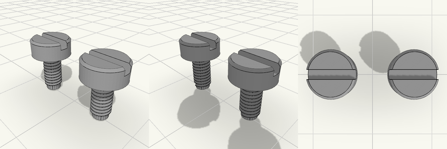
Dos tornillos M3 de rosca fina Ø2,8 mm
Dos tornillos M3 imprimibles e idénticos, pensados para roscar en agujeros laterales con rosca interna M3 de paso 0,5 mm. Cada tornillo lleva rosca externa de Ø2,8 mm (0,2 mm de holgura sobre el nominal) y 6 mm de longitud, con la punta achaflanada, y cabeza cilíndrica ranurada de Ø6 × 2,5 mm. Se imprimen de pie, con la punta sobre la placa y la cabeza arriba, de modo que no necesitan soportes y la ranura queda accesible. Especificaciones Rosca: M3, paso 0,5 mm, Ø exterior 2,8 mm, longitud 6 mm Cabeza: Ø6 mm × 2,5 mm, ranura para destornillador plano y chaflán Cantidad: 2 piezas, separadas 10 mm en la placa para imprimir juntas Orientación: de pie, punta en z=0, cabeza arriba, sin soportes Base de la cabeza plana, no cóncava: apoya sobre una barra de Ø14 mm con poco margen hasta el borde (unos 0,7 mm) Con 6 mm de largo, la punta queda dentro del hueco central de Ø6,6 mm sin tocar la pared opuesta El paso de 0,5 mm produce una rosca fina en FDM. Si no entra tras imprimir, conviene ampliar el agujero receptor a 3,2 mm o sustituir la pieza por un tornillo M3 metálico.
Tornillos M4 avellanados Phillips de repuesto
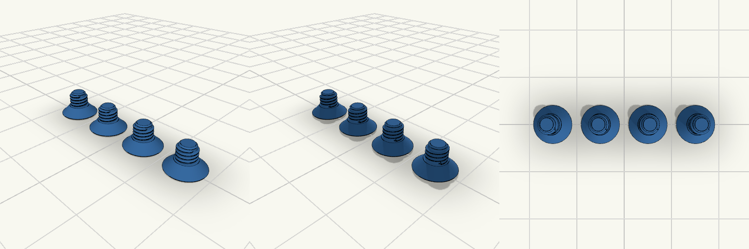
Cuatro tornillos M4 avellanados con cruz Phillips para reponer el que se pierde o se daña al apretar. La cabeza queda al ras de la cara superior y la punta no sobresale por debajo, así que no hay arista que enganche ni tornillo que baile en el agujero. Medidas que deciden el ajuste Rosca M4 métrica, paso 0,7 mm; diámetro exterior de 3,9 mm para que entre con holgura. Cabeza cónica de 90°: 8 mm en la cara superior y 1,8 mm de alto; en la base mide 4,4 mm, algo más que el vástago. Longitud total de 5 mm, cabeza incluida; el vástago roscado mide 3,2 mm bajo la cabeza y la punta va achaflanada 0,4 mm. Cruz Phillips PH2: dos ranuras de 4 mm de largo, 1 mm de ancho y 1,2 mm de profundidad. La rosca engancha unos 2 mm en la pieza inferior. Para imprimir Eje vertical, con la cara plana de la cabeza sobre la cama; no necesita soportes. Capa de 0,2 mm o menos y al menos 4 perímetros. Vienen cuatro, separados 10 mm entre sí en la placa; el conjunto ocupa 38 × 8 × 5 mm. Imprime un par de repuesto: con una cabeza de solo 1,8 mm, la cruz se puede dañar si aprietas fuerte.
U-Turn — Zweiteilige 180°-Schlauchführung
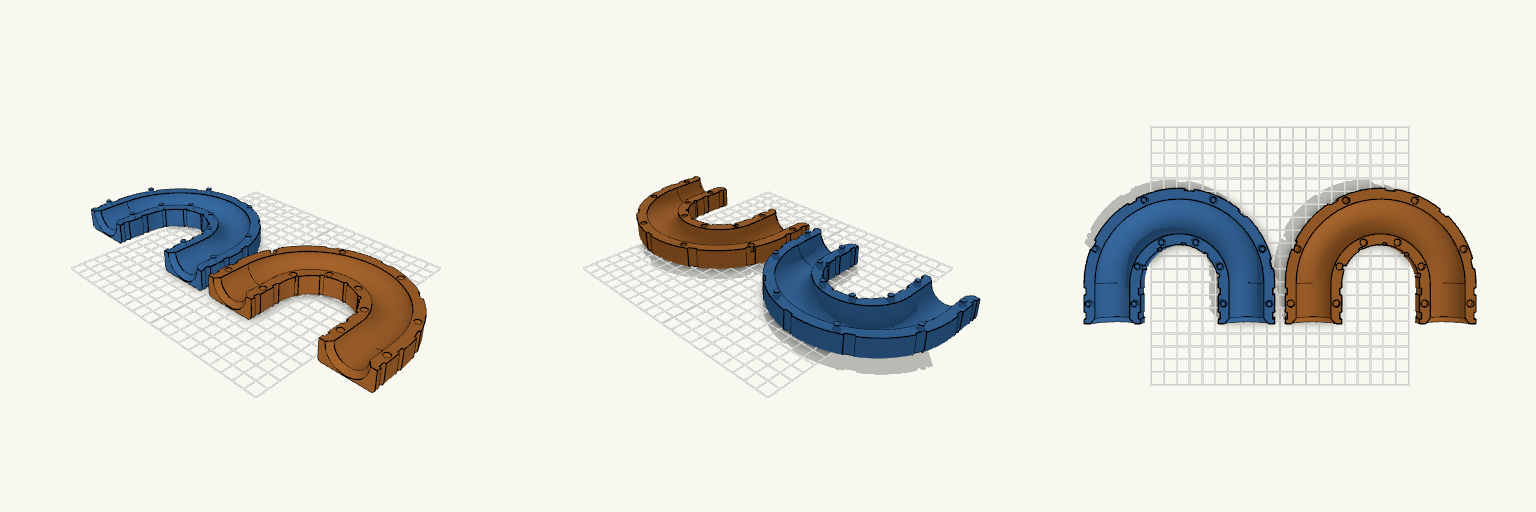
U-Turn ist eine zweiteilige 180°-Schlauchführung, die einen Schlauch mit 25 mm Außendurchmesser in einem gleichmäßigen Bogen umlenkt, sodass Ein- und Auslauf parallel nebeneinander in dieselbe Richtung zeigen. Statt Schrauben oder Muttern halten handelsübliche Kabelbinder die beiden Hälften zusammen: Mehrere außenliegende Nuten laufen um den gesamten Querschnitt, sodass die Binder nicht seitlich abrutschen und nicht in den Schlauchkanal hineinragen. Die flache Außenseite liegt beim Druck unten, die Nut zeigt nach oben — dadurch kommen beide Hälften ohne Stützmaterial aus. Maße Schlauchkanal: 26 mm Innendurchmesser für einen Schlauch mit 25 mm Außendurchmesser Bogen: exakt 180°, Biegeradius 50 mm zur Mittellinie, Mittellinien 100 mm auseinander Gerade Ein- und Auslaufstrecken: je 30 mm, an den Enden auf etwa 33 mm aufgeweitet Wandstärke: 4 mm; Querschnitt 42 mm breit, jede Hälfte 17 mm hoch Kabelbindernuten: 5,2 mm breit und 1,5 mm tief für 4,8 mm breite Binder; Restwand an der dünnsten Stelle 2,5 mm Aufbau Beide Hälften verlaufen über den gesamten 180°-Bogen und tragen je eine halbrunde Nut, die zusammengesetzt einen geschlossenen, kreisförmigen Kanal ergibt. Die Hälfte mit den Zapfen trägt Zapfen von 5 mm Durchmesser und 4 mm Höhe, die Gegenhälfte passende Aussparungen von 5,4 mm Durchmesser — das ergibt ein Montagespiel von 0,2 mm je Seite. Die Zapfen sitzen beidseitig des Kanals, sowohl auf dem Bogen als auch an den geraden Endstücken, und verhindern ein seitliches Verrutschen. Montage Die Hälfte mit den Aussparungen umdrehen, auf die Hälfte mit den Zapfen setzen und andrücken. Anschließend Kabelbinder durch die Nuten führen und festziehen: fünf Nuten verteilen sich gleichmäßig entlang des U-Bogens, je zwei sitzen an den geraden Endstücken. Druckhinweise Beide Hälften werden getrennt gedruckt und anschließend zusammengesteckt; die Kabelbinder übernehmen die Fixierung. Der Kanal ist an beiden Enden großzügig abgerundet, damit der Schlauch ohne Knickstellen ein- und ausläuft.
Cabinet Handl Bumper
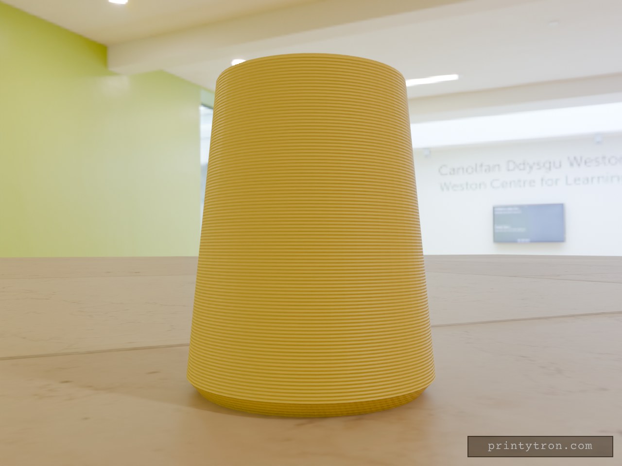
A cabinet handle end that slams into the door or wall now has a cone-shaped TPU bumper to take the hit. The bumper slides over the handle end and stays put on an 11.8 mm blind hole. Key numbers Height: 32 mm Base diameter: 26 mm, with a 1.5 mm 45° chamfer on the bottom edge Narrow end diameter: 20 mm Hole: 11.8 mm diameter, 24 mm deep, opening at the narrow end Print: TPU, base down, no supports needed
Capuchón protector para tornillo de 7 mm
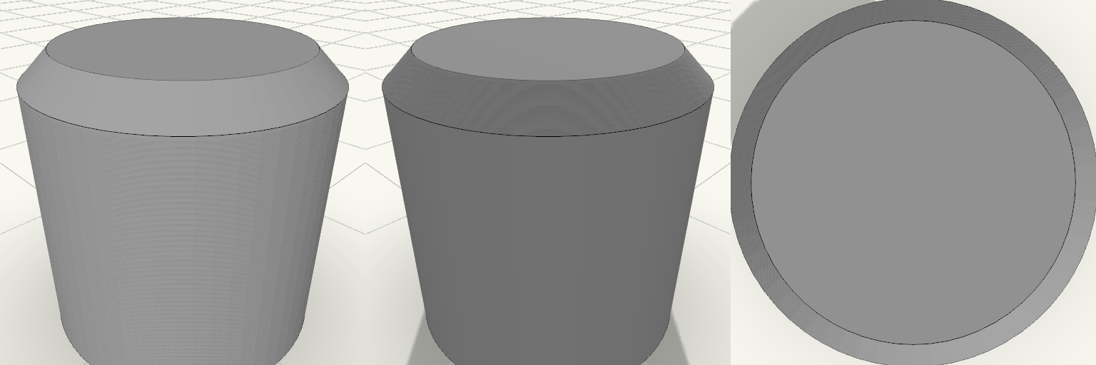
Capuchón cilíndrico con rosca interior pensado para cubrir la punta o la cabeza de un tornillo y dejar el extremo oculto y sin aristas vivas. La rosca interior está hecha para un tornillo de 7 mm con paso de 1,5 mm y 9 mm de profundidad, de modo que la pieza se enrosca en el tornillo. El extremo opuesto es cerrado, y el borde de entrada lleva un chaflán que facilita colocar la pieza sobre el tornillo. Medidas y construcción Rosca interior: para tornillo de 7 mm, paso 1,5 mm. Profundidad roscada: 9 mm. Fondo cerrado: 1,5 mm de espesor. Medida exterior: 10,5 mm de diámetro × 10,5 mm de alto total. Borde de entrada achaflanado para guiar la entrada del tornillo. Pieza única, se imprime tal cual, sin montaje posterior. Antes de imprimir, comprueba que el tornillo tenga 7 mm de diámetro y que el paso sea de 1,5 mm. Si el paso real no coincide, la rosca no enroscará; si el diámetro o el paso son distintos, conviene ajustar la rosca interior en consecuencia.
Barbed End Plug for 1-Inch PEX
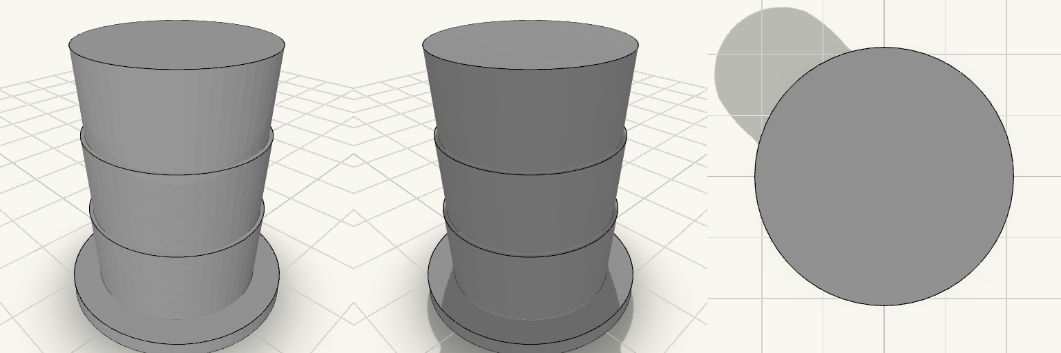
A barbed end plug that dead-ends a 1-inch PEX line. Three tapered barbs rise from a solid 28 mm collar cap, stacked directly on one another so each ring sits flush against the next with no gaps, and they taper from 21 mm to a 22 mm maximum diameter to suit pipe with roughly a 22 mm inner diameter. The collar is a 28 mm cylinder, 3 mm thick, with a 1 mm chamfer on the bottom outer edge, and it is the cap as well as the pipe stop — only about 3 mm of it shows past the barbs, so the stop is shallow. There is no bore: the plug is solid through, about 33 mm tall, sits flat on the plate, and prints as one piece as a 28 × 28 × 33 mm body. Because it seals rather than joins, check the barb fit against your actual pipe before committing to a full run. Remix hooks Barb profile: three tapered barbs stacked flush as one sawtooth suit roughly 22 mm inner diameter pipe. Change the count or soften the taper for harder or softer tubing, but keep the spacing equal to the barb height so the gaps between rings do not come back. Collar: 28 mm across and 3 mm thick, it is only just wider than the barbs. Widen or thicken it for a firmer insertion stop; the bottom outer edge carries a 1 mm chamfer, which can be enlarged or removed to change entry feel. Height: 33 mm overall is a compact cap; stretch the straight run above the barbs if you need more insertion room or a deeper seat. Barb diameter: 21–22 mm is the number to change first for other pipe sizes. The collar and barb spacing can stay put while only the taper moves. Ends: the solid cap is the safe baseline. Extending the same barbed profile out the other side turns it back into a straight coupling, and an elbow or tee is a body swap rather than a barb redesign. Fit check: barb dimensions are nominal, so test against your actual pipe before printing a full run. Pairs with: 1-inch PEX runs that need a temporary or permanent dead end, pressure testing, and capping a line before fixtures go on.
Mantel Clamp with Single Stocking Hook high no thread lenght lower
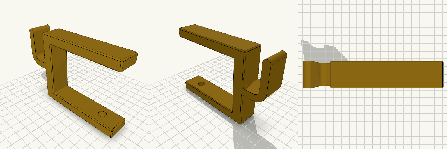
A clamp-on mantel bracket for hanging a stocking, garland or wreath without drilling. The gold C-shaped frame slips over the mantel edge, and a single rounded J-hook on the back carries the decoration. A standard M8 bolt passes through the lower arm and tightens up against the underside of the shelf to lock the clamp (hardware you supply — bolt and nut). The lower arm reaches back far enough to clear a decorative moulded edge, and the frame measures about 119 × 23 × 80 mm on the print plate. The hook is a compact rounded J — 23 mm wide, projecting about 24 mm, with a 5.5 mm inner cradle — raised so its round tip finishes level with the top of the frame at 80 mm; the cradle floor sits about 38 mm up the spine. The frame prints as one piece; the bolt and nut are separate hardware. Starting dimensions Clamp frame: 119 × 23 × 80 mm on the plate, one piece, no supports needed on the arms Opening between the arms: 60 mm (about 2.4 in) — suits a 2 in gap or a 1.5 in mantel with room to spare Arm reach back from the spine: 95 mm (about 3.75 in), sized to clear a decorative edge Hardware hole: plain 8.5 mm clearance for an M8 bolt, 75 mm back, through the 10 mm lower arm — a nut underneath does the clamping Hook: rounded J, 5.5 mm inner cradle, 23 mm wide, projecting about 24 mm, cradle floor about 38 mm up the spine, 26 mm lip with its tip level with the frame top Remix hooks The hardware hole is the first thing to tune: 8.5 mm suits a plain M8 bolt with a nut under the arm; drop it to about 7 mm and tap it if you want the bolt to bite the plastic, add a hex pocket to trap the nut, or resize for M6 if your mantel is light. The 60 mm opening and the 95 mm arm reach are a pair worth changing together — a shallow mantel with a chunky decorative edge wants more reach and less opening, a thin shelf the reverse. Hook geometry is the free variable: stretch the 24 mm projection for deep garland, widen the 5.5 mm throat for thick loops, tighten it for wire wreath frames, or slide the cradle down the spine if a stocking sits too high for your mantel. Frame depth (23 mm) sets how far the clamp stands off the mantel face — trim it for a slim profile, add to it for heavier loads. Duplicate the frame along the shelf for a full swag of garland, or scale it down for a miniature display mantel. Pairs well with a wreath hanger or a matching hook set in the same finish; print the frame in PETG or ASA if it will hang outdoors over the season, and in gold filament to match the finish shown.
Flat-Printing Interlocking Hexagonal Wall Shelf
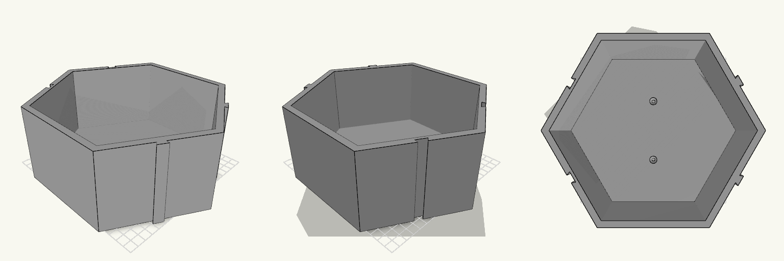
A hexagonal wall shelf that locks to matching units through dovetail keys and slots, so several can form a honeycomb. The back plate has two countersunk screw holes for wall mounting, and the front is open and flush. 170 mm flat-to-flat height, 95 mm deep 8 mm walls, 5 mm back plate Dovetail keys and slots with 0.5 mm clearance per side Printed lying on the back plate, fits a Creality K2 bed PETG recommended, with supports for the dovetails Test one pair of faces first to confirm the fit.
Scatola con porta voltmetro per montaggio laterale
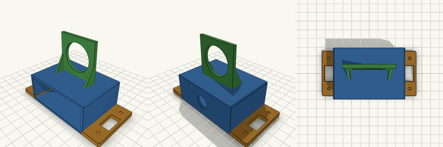
Scatola rettangolare a fondo aperto da avvitare su un mobile, con un pannello verticale sul tetto per il voltmetro. Pensata per stamparsi senza supporti e con poco filamento. Corpo: 70×30×50 mm, pareti da 2 mm Foro da 13 mm sul tetto per i cavi, foro da 29 mm nel pannello voltmetro 40×40 mm Rinforzi triangolari ai lati del pannello, senza sporgenze da sostenere Due alette di fissaggio con fori da 3,4 mm (viti M3), alleggerite da una finestra centrale Stampa: alette appoggiate sul piano, nessun supporto necessario nei rinforzi
Charging Station Marker Nail
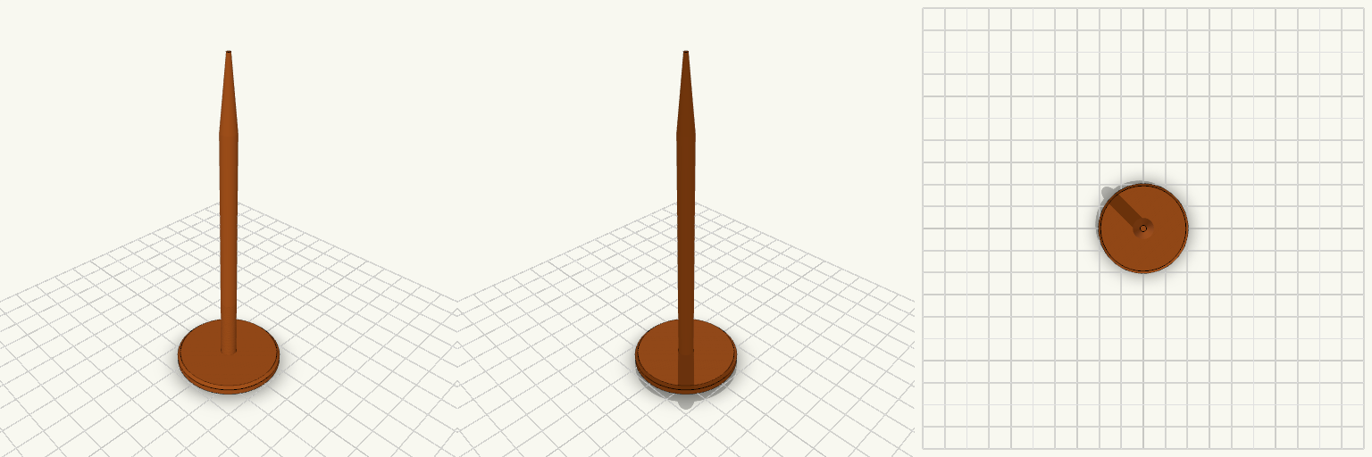
A ground marker nail for holding the position of a robot mower charging station while the charger is stored for the season. It is pushed into the soil where the charger's screw sits in summer. The nail has a wide, flat 40 mm head that stays visible at ground level, a slim 6 mm round shaft, and a tapered point for easy insertion. It prints head-down, so no supports are needed. Head: 40 mm diameter, 4 mm thick, chamfered edge Shaft: 6 mm diameter, about 90 mm long Tip: tapers to a point over 25 mm Overall length: about 119 mm Prints without supports
Abdeckkappe mit 50 mm Innendurchmesser
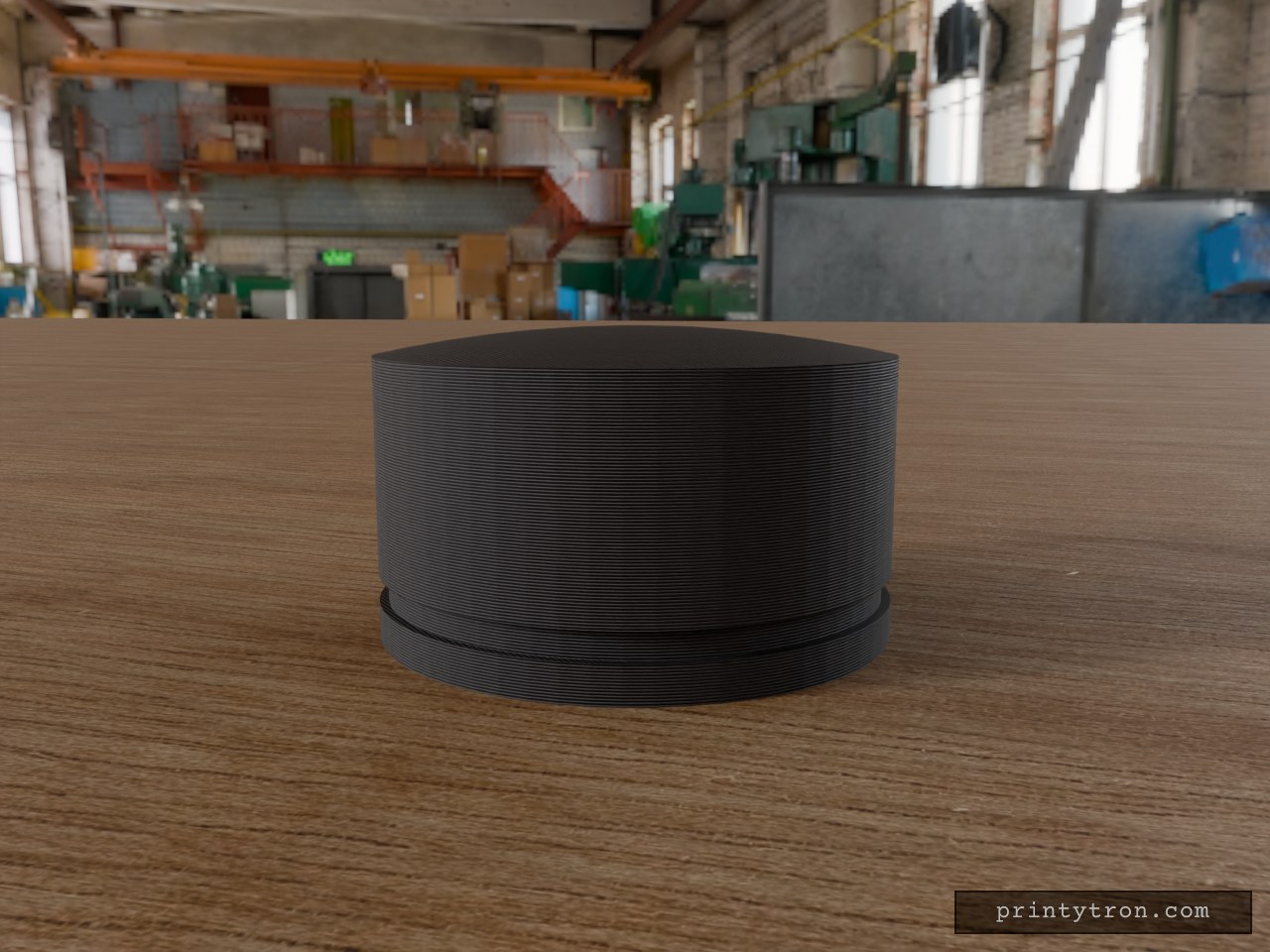
Eine geschlossene Abdeckkappe für Rohre und Öffnungen mit 50 mm Außendurchmesser. Die Kappe sitzt mit 50 mm Innendurchmesser satt auf dem Rohr, die Wandstärke von 3 mm und der leicht nach außen gewölbte Deckel geben ihr Form und Stabilität. Außen umlaufend, knapp über der Unterkante, liegt eine Nut zum Einrasten oder für einen O-Ring. Die Kappe wird in einem Stück gedruckt; Stützen sind nicht nötig, solange sie mit der Öffnung nach unten auf dem Druckbett steht. Innen-Ø: 50 mm Wandstärke: 3 mm, Außen-Ø: 56 mm Gesamthöhe: 33 mm, Deckel leicht nach außen gewölbt Umlaufende Nut außen: 1 mm tief, 3 mm hoch, ca. 4 mm über der Unterkante Wer die Nut innen oder direkt an der Kante braucht, muss die Maße vor dem Druck anpassen — die Kappe selbst passt sonst nur auf Rohre, deren Außendurchmesser zum Innendurchmesser von 50 mm passt.
Eccentric Duct Adapter 125mm
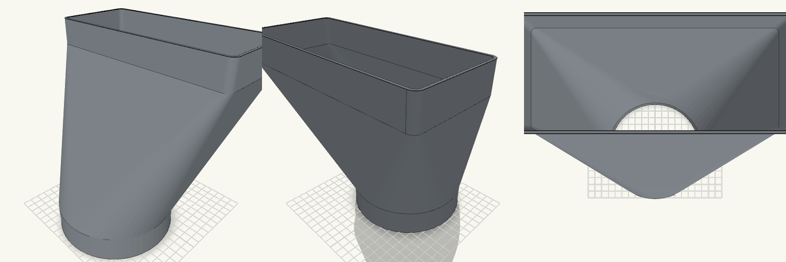
What it's for Bathroom duct adapter that joins a round duct to a flat rectangular duct in one continuous piece. Both ends are female sockets, so the ducts slide into the adapter rather than over it, and the internal passage stays fully open from end to end with no obstruction to airflow. The round socket is bored to Ø132 mm for a free, loose fit over Ø125 mm duct — roughly 3.5 mm of clearance per side, which can be taken up with tape or a gasket if a tighter seal is wanted. Dimensions Round socket: Ø132 mm inner, Ø136.8 mm outer, 30 mm long, 1.5 mm entry chamfer Flat socket: 222 × 92 mm inner, 5 mm corner radius, 30 mm long Transition: 160 mm, smooth round-to-rectangle loft, horizontally symmetric Vertical offset of the flat socket: 72.5 mm Wall thickness: 2.4 mm throughout Overall length: 220 mm Print notes Print as one piece; no assembly and no supports are needed for the open bore. The bounding volume on the plate is about 227 × 189 × 220 mm, so check the build volume before slicing. A 2.4 mm wall prints cleanly in PETG or ABS if the part sees warm bathroom air; PLA works for a dry run-in fit. Remix ideas Change the bore diameter to tune the fit for a different round duct. Adjust the 72.5 mm vertical offset for another mounting position. Lengthen either socket for a deeper grip on the duct.
Tampão com travas para abertura semicircular
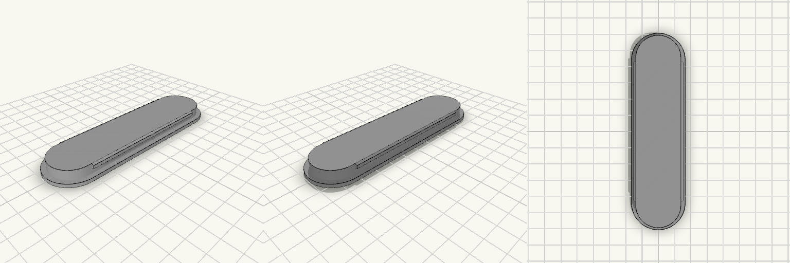
Um tampão para abertura retangular de pontas em semicírculo — aquele vão que fica aberto porque nada encaixa direito nele. A peça assenta por pressão: duas travas embutidas nos lados compridos prendem na abertura, a aba assenta na borda e o interior é oco por baixo, então o tampão cobre o buraco sem virar um bloco maciço. As laterais são maciças, sem fendas: é a parede fina que cede no eixo X na hora de encaixar. Medidas que decidem o encaixe Abertura coberta: 27 × 114 mm, com as duas pontas em semicírculo de raio 13,3 mm; o corpo tem 26,6 × 113,6 mm, já descontada a folga. Aba de 2,1 mm em volta: assenta na borda e impede a peça de afundar no vão. Espessura total: 8 mm, contando a aba — o perfil fica baixo, rente à superfície. Duas travas embutidas, uma em cada lado comprido, com 84 mm de largura cada; não há travas nas pontas, que brigariam com a curva. As travas ocupam a faixa de 5 mm a 8 mm na altura, com ressalto de 3 mm. Parede lateral de 1,8 mm, inteira e sem fendas nem aberturas: a flexibilidade vem só da espessura da parede. Interior oco e aberto por baixo; o topo é fechado por uma tampa de 0,5 mm. Peça completa: 32,6 × 119,6 × 8 mm. Para imprimir Sai em uma peça só, sem montagem, sem parafuso e sem cola. Imprima com o lado da aba para baixo, apoiado na mesa, para as travas saírem limpas. O topo é uma tampa fina de 0,5 mm: reduza a velocidade nas últimas camadas para ele não ondular. O interior é oco e aberto por baixo — dá para escolher o preenchimento e conferir a parede por dentro depois de imprimir. Use um material que ceda um pouco — PETG funciona bem; PLA muito rígido pode rachar a trava no primeiro encaixe. O encaixe depende da parede de 1,8 mm: se ainda ficar rígido demais, afine mais a lateral antes de mexer nas travas, mas abaixo de 1,5 mm a parede começa a ficar frágil.
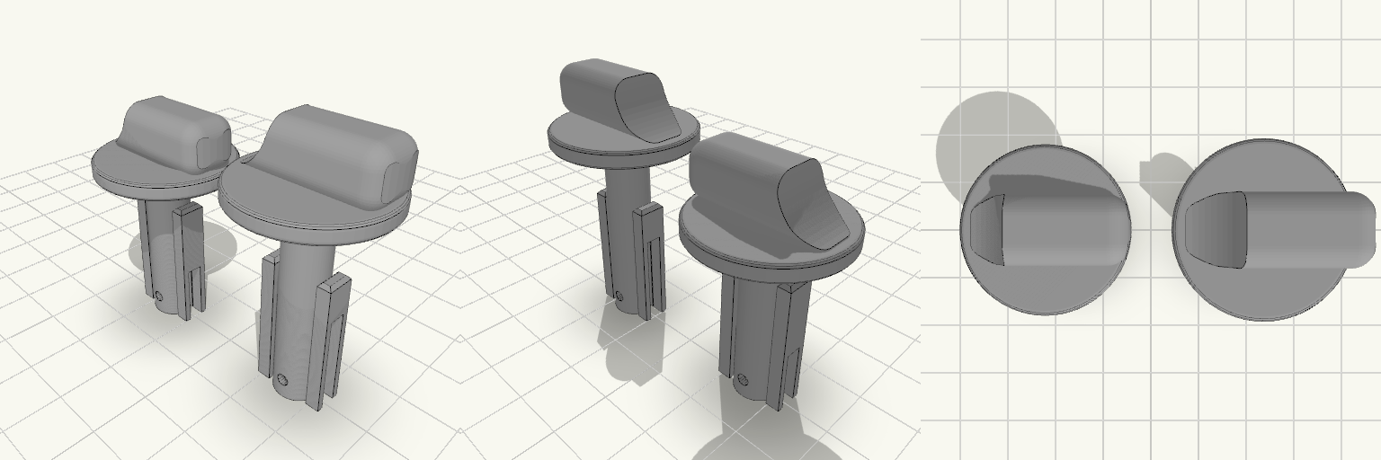
Perilla de estufa de repuesto con vástago reforzado
La perilla de la estufa que gira en falso o se parte deja el fuego sin control; esta perilla de repuesto se calza sobre el caño de gas y se traba con pasador, con el pulgar recortado al contorno del collar y todos los bordes del agarre redondeados para girar sin engancharse. La placa trae dos perillas: la original y una copia con vástago de 35 mm para cambiar el largo según la estufa. Cotas que deciden el calce Dos perillas en la misma placa: la original mide 41,5 mm de alto total (12 mm de cabeza + 29,5 mm de vástago); la copia mide 47 mm de alto total (12 mm de cabeza + 35 mm de vástago). En la placa ocupan 58 × 26 × 47 mm. Vástago: 8 mm de diámetro exterior, con dos aletas planas de refuerzo de 24 mm a los lados; en la copia, las aletas quedan en la zona de la punta. Vástago hueco: orificio de 5,5 mm de diámetro, abierto en la punta. En la original llega a 26 mm de profundidad y queda ciego en los últimos 3,5 mm hacia la cabeza, con paredes de aproximadamente 1,25 mm; la copia mantiene el mismo orificio de 5,5 mm. Agujero pasante: 2,2 mm de diámetro, horizontal, con el centro a 3,5 mm del extremo inferior; cruza la cavidad del vástago, así que la chaveta atraviesa el caño de gas. Endija: 3 mm de ancho, abierta en la punta; va a 90° del agujero del pasador, atraviesa el vástago y corta también las aletas laterales, dejando el extremo dividido en dos mitades flexibles. En la original llega a 11 mm; en la copia llega a 17,5 mm, la mitad de su vástago. Cabeza: collar de 26 mm de diámetro por 3 mm de alto; el pulgar mide 26 mm de ancho, 10 mm de grosor y 9 mm de alto sobre el collar, ya no pasa el contorno del collar, es plano de un lado y baja curvo del otro. Todas las aristas del pulgar tienen 3 mm de radio; los bordes del collar tienen 0,8 mm. Cada perilla se imprime de una sola pieza; la endija no separa el modelo, solo deja flexibles las dos mitades del extremo. El acabado negro mate sale del filamento que elijas, no de la geometría. Antes de imprimir, mide el diámetro del caño de gas y el del pasador: el hueco del vástago y el agujero pasante son las dos cotas que no perdonan, y si no coinciden es mejor ajustarlas antes de gastar material.
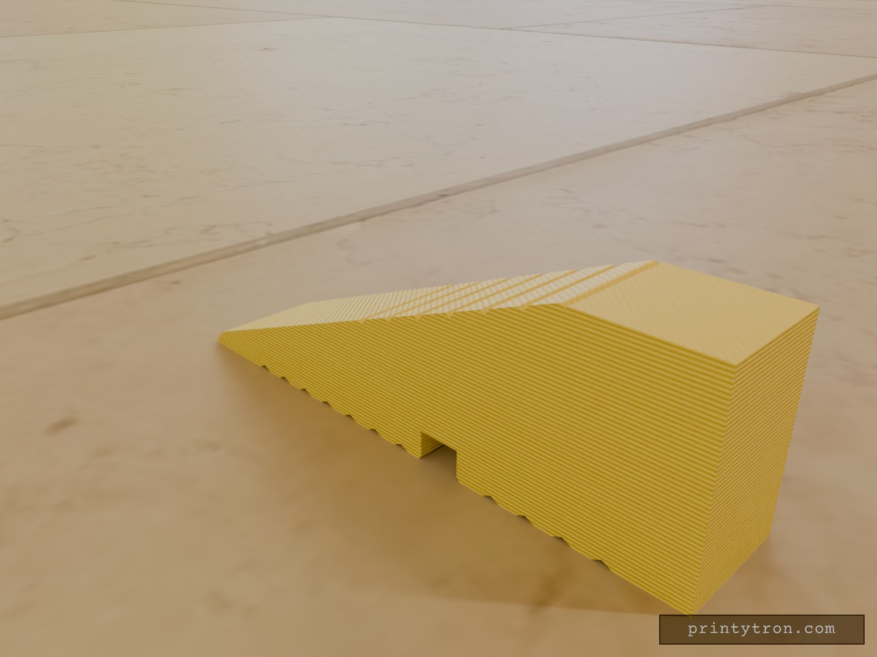
Doorstop Wedge Rib Clip
A doorstop wedge with the low, hard-working profile of a chalk wedge, cut to a 10 mm width to grip the raised PVC rib on a balcony door sill. The underside carries a straight snap-fit groove that presses over the rib, the thin tip lets the door glide across, and the block behind it stops the door dead so it cannot swing open while you are out on the balcony. The top rises from a 1 mm tip to a flat 16 mm shelf — the ramp reaches that height about 39.5 mm back from the tip and then runs flat to the fat end. Both the top and bottom faces carry shallow V-ribs across the width: grip where a hand or a door meets the wedge, and a lightly textured finish underneath. Design notes 50 × 10 mm footprint with a 16 mm flat top; the ramp climbs from a 1 mm tip to the shelf, and the shelf’s front edge is left sharp Bottom groove 3.6 mm wide (3.4 mm rib plus 0.2 mm clearance) and 2.5 mm deep, flat-bottomed with a 0.3 mm entry chamfer, centred 20 mm back from the fat end V-ribs run 3 mm apart at 0.4 mm deep; bottom ribs start about 8 mm from the tip and stop clear of the groove so its edges stay clean, while top ribs begin where the wedge is thick enough to cut into 0.5 mm chamfers along the top edges, and a 1 mm 45° bevel at the tip to help the door ride over Printing Print flat on the bottom face with the groove facing down, in PETG at 0.2 mm layers, 4 walls and 40% infill.
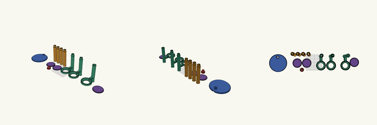
1.5 m Corner Lamp with Three Lamp Trays
A 1.5 m floor lamp for a room corner, built around a round 240 mm base and a hollow central pole. Three arms extend toward the room at different heights, each ending in a round cradle for a disc-style LED lamp of the kind used for model lighting. The lamps drop in face-down and shine through the opening in the floor of each cradle, and each holder has a removable top cover. The lamp prints as separate parts: a round base, hollow pole sections, three arm sections, a top cap and three lamp covers. The parts are laid out as separate pieces in four groups, each group fitting inside a 250 mm bed, so each one can be sent to its own plate in the slicer. Every part is at most 230 mm tall, so build height is not a limit. The pole sections push together with spigot-and-socket joints; dry-fit first, then glue once the fit is checked. Cables run inside the 26 mm bore in the pole and out through a groove under the base to the back edge. Build plates: four groups — base; four pole sections with two covers and the top cap; two arm sections; top arm section with the third cover Base: round disc 240 mm across and 14 mm thick, with a 3 mm chamfer and a plug for the first pole section Overall height: 1500 mm Pole: hollow sections, each 210 mm long, with a 26 mm bore for cables Arm heights: about 480, 900 and 1320 mm Cradle: 104 mm pocket, 114 mm outer ring, 17 mm deep, 70 mm floor opening Cover: 114 mm disc with 100 mm lip, removable, print flat with the lip up Cable route: 20 × 9 mm arm channel, cable notch in the rim, 24 mm exit groove under the base Printing: arm sections need supports under the arm and tray Assembly: push-fit joints with 0.3 mm clearance; glue after checking the fit Each cradle has a 104 mm pocket inside a 114 mm outer ring, with a 70 mm floor opening that lets the light out. The pocket and floor ring seat the lamp; the removable cover is a 114 mm disc with a 100 mm lip that sits inside the pocket. The cradles are sized around a disc-style lamp roughly 100 mm across; check the actual lamp diameter and thickness before printing. Each arm has a 20 × 9 mm internal channel that opens into the pole bore and runs to the cradle, sized to pass a USB plug. The disc base fits a 250 mm plate with about 5 mm to spare on each side, so check your slicer's plate margins before committing the print. The cradles reach about 170 mm out from the pole, past the front edge of the base. With three lamps loaded, add weight in the base or secure the lamp if it will be somewhere it can be knocked.
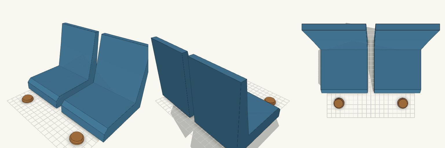
Faceted Weighted Bookend Pair
A pair of L-shaped bookends with a faceted upright and a hollow, sealed foot. The cavity can be filled with sand or coins through a filler hole in the underside, then closed with a printed plug. Weighting the foot is meant to keep paperbacks from toppling on a shelf. What it's for Holding up paperbacks and other light books that tip over on a shelf. Adding ballast after printing, so the print stays light and quick until you fill it. Printing as a matched pair: two identical bookends and two plugs. Dimensions Height: 130 mm. Foot: 100 mm wide by 120 mm deep, 25 mm tall at the front. Sealed cavity: about 90 x 106 x 16 mm inside the foot. Filler hole: 20 mm diameter in the underside, with a counterbore so the plug sits flush. Plugs: 0.3 mm clearance all round, printed separately beside the bookends. Overall layout: both bookends side by side, about 215 mm wide. Print notes The cavity ceiling is a 90 mm bridge. Turn on supports if it sags. Print the bookends upright on their feet. The plugs print flat. After filling, glue the plug into the recess so it sits flush and the bookend doesn't rock. Remix ideas Extend the cavity up into the upright for more ballast. Add a felt or cork pad to the underside. Change the facet angles or upright height for a different look. Increase the foot depth for taller or heavier books.
Need a part that doesn't exist yet?
Start building →