Vertical Switch Dock Stand
Created 3 months ago
Description
Stand your Nintendo Switch dock on its side to reduce its footprint on crowded shelves or desks. This bracket features a 52mm U-channel designed to securely hold the dock vertically, supported by an extended base plate to prevent tipping.
A side extension block provides dedicated storage for two spare Joy-Con straps, keeping accessories organized alongside the main unit. The base includes a central cutout for ventilation and reduced material usage.
Features:
- 52mm central cradle slot for vertical dock mounting
- Extended base footprint for increased stability
- Dual drop-in slots for standard Joy-Con straps
- Central ventilation cutout for airflow
Photos
Technical views
More like this
Explore more in Desk & Tech →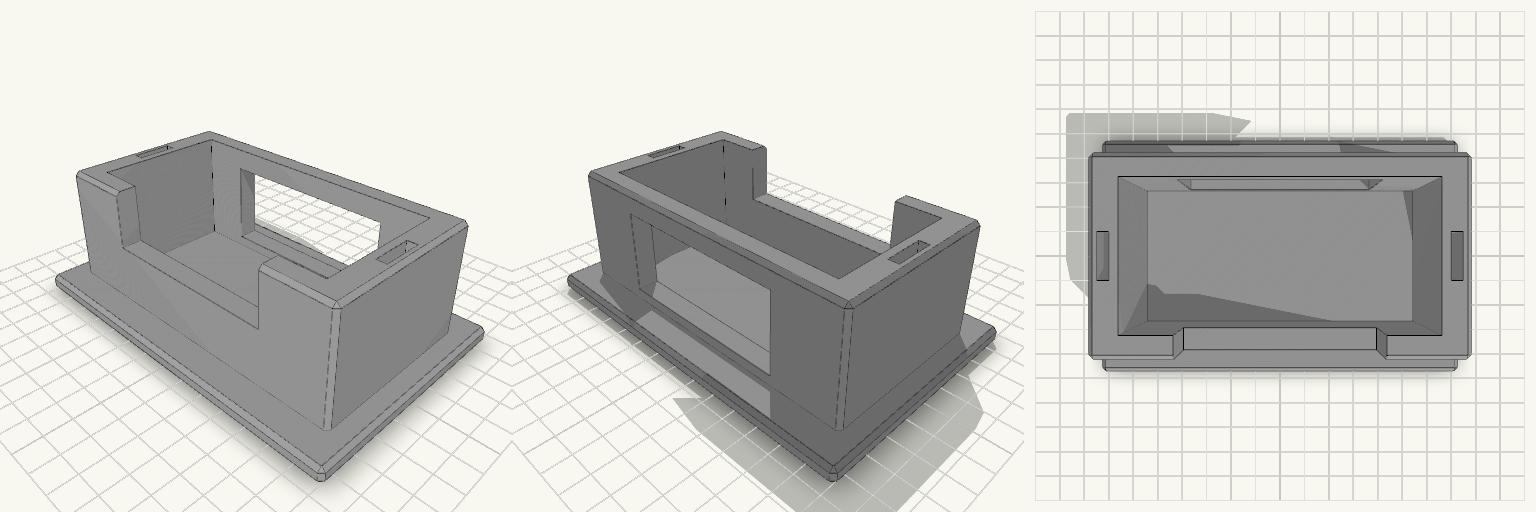
Vertical Switch Dock Stand with Strap Slots
A Switch dock lying flat eats shelf space, and a dock stood on its end tips over the first time someone pulls a cable. This stand holds the dock upright in a snug pocket on a wide flat base, and keeps two spare Joy-Con straps in slots in the side walls. What it does Holds the dock on its end so it takes up a footprint of about 142 × 92 mm instead of its full 175 mm length lying down. Front wall is cut down in the middle, so you can grip the dock to lift it out. A 70 mm opening in the back wall lets the power, HDMI and USB cables leave without bending against the stand. Two 4 × 16 mm slots, one in each side wall, hold spare Joy-Con straps. Numbers that decide fit Pocket: 106 mm wide × 52 mm deep, for a dock of roughly 104 × 49 mm. That leaves about 1 mm of play on width and 3 mm on depth. Pocket depth: 44 mm, above a 6 mm base. Overall: 142 × 92 mm base, 50 mm tall. Side walls: 10 mm thick. Front and back walls: 8 mm. Printing Print flat on the base, with no supports needed. Chamfered edges, 1.5 mm. Any common filament works. PETG or PLA is fine for the load. If your dock is a tight fit or loose, adjust the pocket width and depth to match.
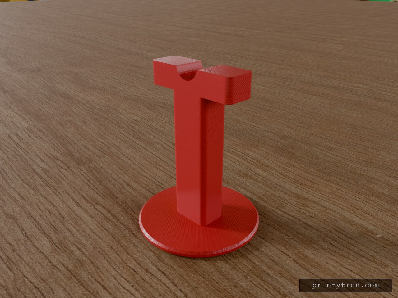
Bedside Reading Glasses Stand, 18mm Bridge
A freestanding bedside stand that holds a pair of reading glasses by the bridge, so they rest off the nightstand and out of the bedding. The top of the column is shaped into a rounded nose-bridge saddle, 18 mm wide at the rim, matching the typical lens-to-lens distance on standard reading glasses. A 90 mm round base keeps the stand upright. Specs Overall size: 90 mm diameter x 116 mm tall Base: 90 mm diameter, 5 mm thick, chamfered edge Column: 30 x 22 mm cross-section, rounded vertical corners Top block: 70 x 22 mm, 16 mm tall Saddle: round dip, 18 mm wide at the rim, 8 mm deep Single-piece body, prints base-down with no supports needed Suggested material: PLA or PETG; 3 or more perimeters for a stiff column Use Place on a nightstand and hang the glasses by the bridge across the saddle. The wide top block and 90 mm base keep the stand stable under light glasses.
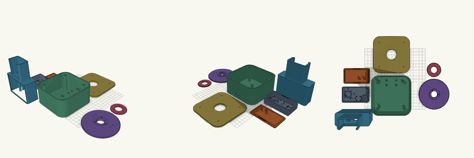
Modular Voice Assistant Enclosure with Rotating Desk Dock
A two-part enclosure system for a modular AI voice assistant: a pocket-sized "Brain" that works on its own, and a desktop station that docks it, swivels a full 360° and carries a 3.5-inch touchscreen behind a removable bezel. Both halves share the same matte-black design language — rounded corners, smooth surfaces and 2–2.5 mm walls — and print as eight separate pieces. What it's for Brain — houses an ESP32-S3 N16R8 board, an INMP441 I2S microphone, a MAX98357A amplifier and a 20 mm speaker behind a grille. A circular LED ring glows through a 0.8 mm front skin for listening, thinking and speaking states; there is no display of its own. A USB-C port sits on the short end, and the unit runs standalone once lifted off the dock. Desk station — a weighted base with a bolted lid carries a swivel plate and the dock tower. The Brain drops into the tower pocket from above with its face still visible, and a USB-C plug cradle in the pocket floor lines up with the port. Display — the tower front takes a standard 98 × 56 mm touchscreen module in landscape, held on four M2 bosses and framed by a bezel that drops into a recess in the front face. Removing four screws frees the display for replacement, and a flat-cable slot below the opening routes the ribbon into the cavity. Rotation — the swivel plate's hollow stem passes through the lid, a retaining ring screws on underneath, and the cable runs down the centre of the stem, so the tower turns 360° without twisting the lead. Dimensions Brain: 85 × 50 × 25 mm overall, with a snap-fit rear cover. Desk base: 120 × 120 mm with 22 mm corner radii; base, lid and swivel plate stack to 65 mm. Dock tower: 104 × 40 × 119 mm, docking the Brain vertically above the display section. It overhangs the 100 mm swivel plate slightly at the front and rear corners. Display opening: 84 × 54 mm, with mounting bosses behind the wall at ±46 × ±25 mm and M2 pilot holes; bezel 100 × 60 × 2.5 mm. Walls: 2–2.5 mm throughout hollow cavities. Print notes Print the Brain shell face-down for a smooth front skin; the LED ring, microphone port and speaker grille all sit in that face. The rear cover snaps on with two bump-and-groove pairs along the long sides; pads on its inside hold the ESP32 down. The tower's internal floor and the display window bridge wide spans, so expect a little support in the dock tower only. Everything else is oriented to print without it. Print the bezel flat; it is a thin frame and needs no supports. PLA or PETG both work; four rubber-foot recesses under the base are worth filling. All eight pieces — Brain shell, rear cover, desk base, base lid, swivel plate, retaining ring, dock tower and display bezel — are separate. The lid bolts on at four corners and the display bezel screws in from the front. Compatibility The display bosses use M2 pilot holes; check your module's hole spacing before driving screws, since pinouts vary between boards. The dock pocket is sized for the Brain as drawn — if you change the Brain's shell, adjust the pocket in step. Remix ideas Lean the dock back a few degrees for a more natural viewing angle if you can accept the extra support. Swap the removable bezel for a blank panel or a vent if your build has no screen. Scale the docking pocket to fit a different companion device while keeping the same swivel mechanism.
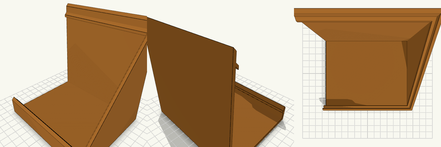
cuña tablet grande vertical parte dcha
Mitad derecha de una caja en cuña hueca, abierta por arriba, con base, frente y trasera cerrados. Se imprime apoyada sobre la base y se une a la mitad izquierda por el corte central. Ancho de la pieza: unos 126,5 mm en X Fondo: 105 mm en Y Altura: 20 mm delante y 130 mm detrás Paredes y base: 3 mm Listón interior perimetral de 3 mm, 8 mm bajo el borde superior Corte plano sin encaje, para pegar
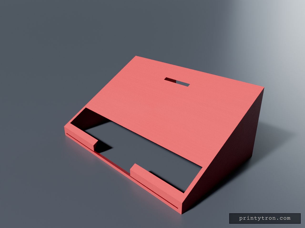
30° Tilted Stand for 118x84mm Keypad
Wedge-style desk stand that holds a 118x84mm macro keypad at a 30° tilt, so the keys face the user instead of lying flat. The pad sits in a recessed pocket that grips its base on all four sides to stop it creeping during use. A finger notch at the front edge lets the pad be lifted out. A cable slot at the back edge routes the cord away from the desk surface. Specs Pad size: 118 x 84 mm Pocket clearance: 0.3 mm per side (0.6 mm total on each axis) Tilt angle: 30° Overall footprint: about 124 x 80 mm, roughly 53 mm tall at the rear Wall thickness: 2.5 mm Front notch: 40 mm wide finger cut-out for lifting the pad Cable slot: 24 mm wide, centered on the back edge Underside: flat; add rubber feet or tape for grip on smooth desks Print orientation: flat side down, no supports needed Notes Check the pocket depth and cable slot position against the actual pad before printing. If the cable exits somewhere other than the center of the back edge, the slot position needs to be moved.
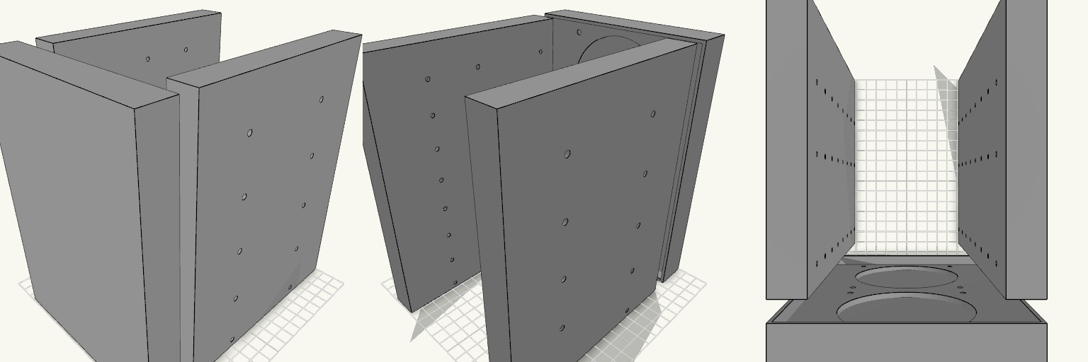
Octobay — 5.25" to 3.5" Drive Cage
Octobay turns a five-bay stack of half-height 5.25" slots into room for eight 3.5" drives, and adds a 25 mm front cage that carries two 92 mm fans. The outer side faces take M3 heat-set inserts, so the whole cage screws into the case's 5.25" rails instead of resting on them. Everything is one printed part: the drive stack, the side mounting blocks and the fan cage print as a single body. Because the fans close off the front, drives now load from the back. The fan cavity behind the grille is hollow, so air still passes through to the drive stack. Dimensions Overall: 145 mm wide × 197.5 mm deep × 205.5 mm tall Fits: five half-height 5.25" bays Holds: eight 3.5" drives, stacked vertically Drive channel: 102.6 mm wide — 1 mm of play around a 101.6 mm drive Mounting 20 insert holes, 10 per side, for M3 heat-set inserts — 4.2 mm across and 6 mm deep Two insert holes per bay, at 41.3 and 117.5 mm from the front, 6.35 mm above each bay floor Solid blocks sit behind each hole to give the inserts something to bite into Three M3 screw holes per side per drive, at 14, 76.6 and 117.6 mm from the front Cross ribs sit clear of the screw holes so a screwdriver can reach every fastener Fan cage Two 92 mm fans, stacked vertically on the 25 mm front section 88 mm fan openings with 4.4 mm screw holes on the standard 82.5 mm square pattern Hollow cavity behind the fans feeds air to the drive channels Print notes Drive channels are open at the back, top and bottom, and the gaps between the inner and outer side walls are open for cable routing. Screw and insert positions and the 205.5 mm height follow common 5.25" bay standards; they have not been checked against a specific case, so measure your bay rails and drives before printing.