Wall Vent Fan Adapter
Made by WittyManta
Created 3 months ago
Description
A custom transition duct that connects a rectangular wall vent to a round inline fan port. The geometry funnels air 90 degrees upward into the fan while maintaining a smooth internal path to minimize turbulence and noise.
Features included:
- Inlet: 360x210mm rectangular opening with a flat back.
- Outlet: 157mm internal diameter socket positioned 116mm outward and 250mm high.
- Mounting: Six countersunk holes for #6 wood screws on the top and side flanges.
- Sealing: Integrated channels for foam tape on the rear of the flange and the underside of the bottom foot.
Images
More like this
Explore more in Home & Fixtures →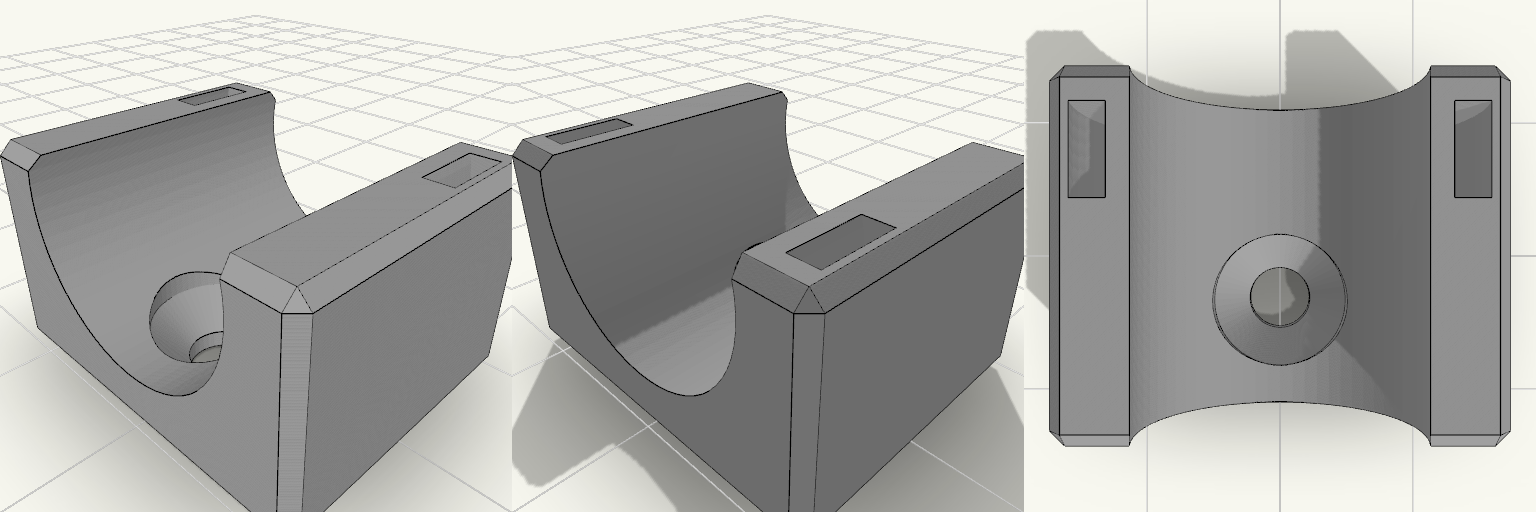
Industrial Saddle Wall-Mount Air-Hose Clip
A plain block with a channel across its top and a single hole sunk into the floor of that channel — drive a drywall screw through it, drop the 5/8″ OD air hose in, and the fixing disappears beneath the hose. A slot cuts through the other half of the block, so a zip tie loops down over the hose and cinches it without ever crossing the screw. No side tabs, no bracket ears, nothing protruding past the saddle: a small, purely functional piece of wall hardware with a squared-off, industrial silhouette. Design notes Top channel sized for 5/8″ OD air hose, with a little clearance. Countersunk screw hole sits in the channel floor with a 9 mm countersink, wide enough for a typical drywall screw head and hidden once the hose is seated. Zip tie slot is offset to the far half of the block, clear of the screw area; takes a common tie up to about 5 mm wide. Load order matters: drive the screw first, then lay the hose in and tension the tie. With a single fastener the block can spin before the hose is loaded — snug the screw down before fitting the hose so it stays square to the wall. Block is 20 mm long, 24.3 × 20 × 14.1 mm overall as it sits on the build plate. Prints as a single body; screws and zip ties are separate hardware.
Klarstein DryFy 50L 150 mm Exhaust Adapter
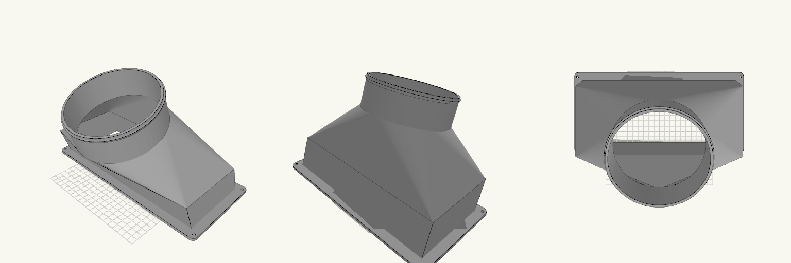
Rectangular-to-round exhaust adapter for routing a 150 mm vent hose from a Klarstein DryFy Connect 50L dehumidifier. The part bolts over the unit's 285 × 120 mm rectangular exhaust port and rises through a 50 mm straight rectangular section before lofting to a round spigot that slides inside a 150 mm hose. The rectangular body leans 20° toward -Y, and the spigot carries a further 20° tilt in the same direction, so the hose leaves the unit well off vertical. The rear of the spigot is pulled back into line with the rear wall of the leaning body, so the back of the adapter is one straight, continuous face with no bulge or kink at the transition; the front still curves as the rectangle narrows to the round spigot. The flange sits flat on the print plate; the overhanging body and spigot will need support. Specifications Overall size: 315 × 220.9 × 186.3 mm as it sits on the print plate Mounting flange: 315 × 150 mm, 4 mm thick, sized to cover a 285 × 120 mm rectangular port Four 4.5 mm screw holes, one in each flange corner Straight rectangular section: 50 mm tall above the flange, leaned 20° toward -Y Transition: 60 mm loft from the rectangle to a round spigot Hose spigot: 148 mm outside diameter, 50 mm long, set at 20° toward -Y on top of the body lean, for a 150 mm hose Combined body lean and spigot tilt put the hose axis roughly 40° off vertical, toward -Y Straight back face: spigot rear wall aligned with the rear wall of the leaning body Retaining ridge near the spigot end Wall thickness: 2.4 mm The angled spigot ends in an elliptical cut face; the hose slides on along the tilted axis Flange sits flat on the print plate; supports required under the leaning body and spigot Screw hole positions are a nominal layout; check them against the actual port before printing if an exact screw match is required The rectangle-to-round change is steep over 60 mm; expect visible stepping on the loft unless printed with fine layers Check that the angled spigot clears the wall or obstructions behind the unit before printing
Hideaway — Türrahmen-Batteriebox
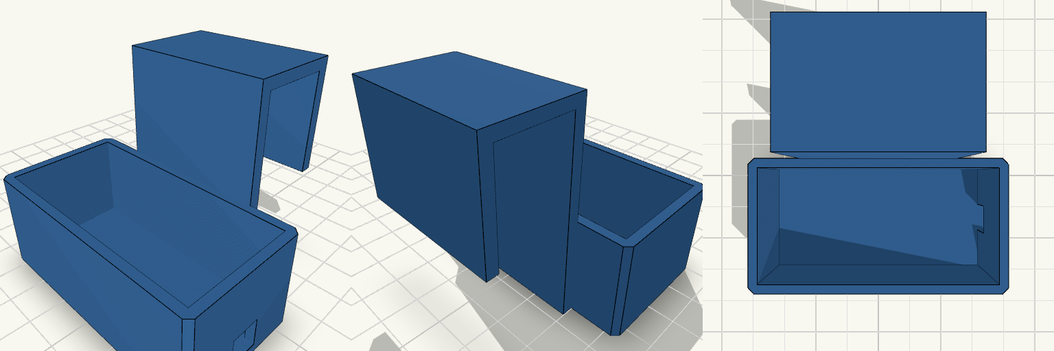
Hideaway ist eine kleine, oben offene Box mit Haken, die über einen Türrahmen gehängt wird und eine Batteriebox für Lichterketten verdeckt. Der Haken sitzt an der Rückseite, der Kabelausschnitt wandert seitlich aus der Box, damit die Vorderwand geschlossen bleibt. Maße Innenraum: 62 × 30 × 24 mm (passend für eine 3×AA-Batteriebox) Haken: für Türrahmen von ca. 20 mm Dicke, 40 mm breit Wandstärke: 2,4 mm Kabelausschnitt: 8 × 8 mm in der rechten Seitenwand, knapp über dem Boden Hinweise Ein Teil, kein Deckel – oben offen Vorderwand geschlossen, Kabelauslass seitlich Ohne Stützen druckbar, Rückseite flach auf das Druckbett
8.35 mm Fiberglass-Rod Joiner with Camera Arm
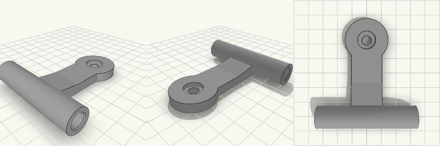
Replacement two-way joiner for the top-front-center of a fiberglass-rod printer enclosure. It splices two nominal 8.2 mm rods end-to-end and carries a flat-lying arm with a screw boss for a Sercomm RC8110 camera. Print it as one piece with the arm flat on the bed, then rotate the part about the rod axis during installation to aim the camera downward and toward the bed center. Specifications Rod sockets: 8.35 mm ID, 30 mm deep per side, 0.5 mm entry chamfers, separated by a 3 mm solid center stop; 63 mm overall sleeve length. Sleeve: approximately 14.35 mm OD with 3.0 mm wall thickness. Arm: 20 mm wide and 6 mm thick, extending 50 mm from the sleeve, with a root block and gusset blending it into the sleeve. Camera boss: 28 mm diameter and 6 mm thick, with a 6.6 mm through-hole and a 12 mm × 2 mm counterbore for a 1/4"-20 camera screw. Print footprint: 63 × 71.2 × 14.4 mm as oriented on the plate; the teardrop socket bores and flat arm are intended to print without support. Fit: press-fit for measured 8.19–8.20 mm rods; PETG wall thickness is sized to resist splitting and bending from the tensioned enclosure fabric.
Twist-On Portable AC Port Cap
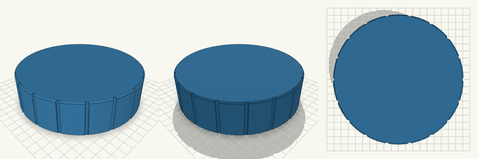
A screw-on lid in the spirit of a big jar cap, sized to seal the wall bracket that takes a 6 inch portable AC hose. The inside carries a female thread that mates with the bracket's 145 mm male thread, so it twists on the same way the hose does. Design notes 12 mm pitch, 5 mm thread depth, 2.5 mm clearance over the 145 mm thread 155 mm outer diameter with a 3 mm closed top and thin walls to save print time Scalloped grip notches around the rim Prints open-side up or top-down; the thread is coarse, so a 0.4 mm nozzle is fine
StrapSlot — Rectangular Velcro Strap Keeper
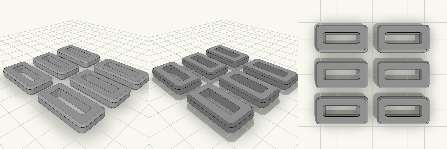
StrapSlot is a rectangular slot ring made for velcro straps — a buckle ring, strap keeper, or loop in one compact part. The internal opening is a clean 20 × 6 mm slot, and the 4.7 mm body uses 4.5 mm walls with rounded corners for a tidy outer profile. A 1 mm chamfer on the outer top and bottom edges softens the outside of the ring, while the slot edges stay square. Use it to keep a strap flat and contained, or as a replacement ring where a rectangular slot is needed. Dimensions | Feature | Size | | --- | --- | | Ring (each) | 29 × 15 × 4.7 mm | | Internal slot | 20 × 6 mm | | Wall thickness | 4.5 mm | | Outer edge chamfer | 1 mm on top and bottom | | Slot edges | Square | | Corners | Rounded | | Full set footprint | 63 × 55 mm, 4.7 mm tall | In the set Six identical rings, arranged in a 2×3 grid with 5 mm gaps between them. The whole set sits flat on the plate at a single 4.7 mm height, so it prints as one batch. Snap or separate the rings after printing to use them individually. Fit notes The 20 × 6 mm slot is the critical fit dimension; check your strap width and thickness against it. The 4.7 mm overall thickness sets the ring depth. The 4.5 mm walls, rounded outer corners, and 1 mm outer-edge chamfer define the outside shape.