Zauberstab final
Made by HingeGuppy
Created 21 days ago
Description
What it's for
Zweiteiliger Zauberstab aus Griff und Spitze, gebaut für eine UV-Taschenlampe im Griff. Der Griff bietet 97 mm Innenhöhe, sodass die Lampe vollständig unterhalb des Bajonettverschlusses sitzt; die hohle Spitze lässt das UV-Licht oben austreten. Außen liegt ein glatter Kern mit vier runden, spiralförmig aufgelegten Teigsträngen, die wie um den Stab gelegte Teigbahnen wirken. Ein innenliegendes Bajonett mit Rastnocke hält die Teile bündig zusammen und sichert gegen unbeabsichtigtes Aufdrehen. Vier Bodenlöcher im Griff erlauben den Zugang zum Druckknopf der Lampe.
Dimensions
- Griff: 99 mm hoch, 97 mm Innenhöhe, Innen-Ø 21,8 mm; Lampe sitzt unterhalb der Bajonettnut.
- Spitze: 135 mm inkl. Zapfen; Lichtkanal von 18 mm unten auf 9 mm oben; Wand im Bajonettbereich mindestens 1,5 mm.
- Außen: glatter Kern Ø 26,4 mm; vier Stränge unten ca. 5 mm breit und 1,4 mm hoch, nach oben ca. 2,5 mm breit und 0,7 mm hoch; größtes Außenmaß ca. Ø 29,2 mm.
- Bajonett: innenliegende Nut im Griff, Nasen an der Spitze, Rastnocke; Einführschlitz bis zur Oberkante; Muster auf die 45°-Endstellung abgestimmt.
- Boden: vier Löcher Ø 3,75 mm, enger zur Mitte gesetzt.
Print notes
Griff und Spitze werden getrennt gedruckt und über den Bajonettverschluss verbunden. Die Außenkontur ist glatt ausgelegt; das Relief der Teigstränge liegt als aufgesetzte Struktur darüber. Für eine saubere runde Außenwand ist eine feine Auflösung sinnvoll. Die Rastnocke ist als spürbarer Widerstand ausgelegt; je nach Drucker und Material kann der Eingriff straffer oder weicher ausfallen.
Remix ideas
- Anzahl der Stränge oder Windungszahl über die Höhe ändern.
- Strangquerschnitt dicker für kräftigeres Relief oder dünner für eine glattere Oberfläche.
- Griffhöhe und Lichtkanal an eine andere Taschenlampe anpassen.
- Rastnocke stärker oder schwächer auslegen.
Images
More like this
Explore more in Workshop & Tools →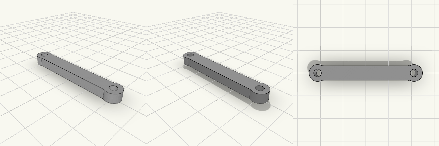
40mm 孔距平面传动连杆 Ø3.2
平面传动连杆,两端为圆头,各带一个通孔,可平放直接打印,无需支撑。 孔中心距:40 mm 杆身:宽 6 mm,厚 4 mm 端部圆头直径:7 mm 通孔直径:3.2 mm(适配 M3 螺栓) 孔周壁厚约 1.9 mm 打印方式:平放,无支撑,建议 PLA / PETG
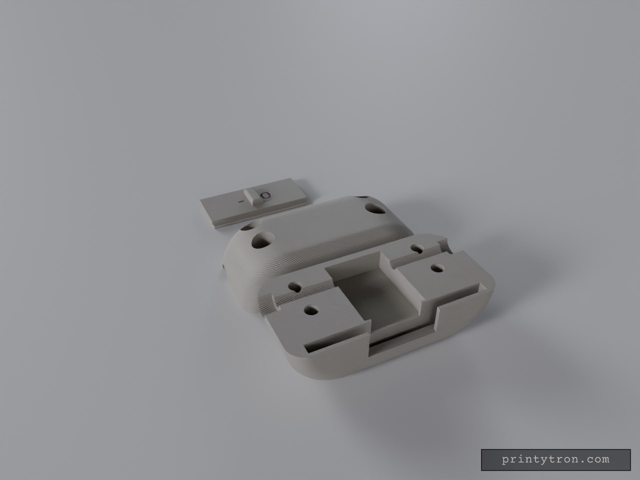
Oval Electrical Switch Housing with Slider
A pebble-shaped housing for a small electrical switch, built as two lengthwise half-ovals plus a separate sliding cover. The front and back halves split along the wire axis, and the seam runs through the middle of both 3 mm wire holes and the switch pocket. Lay the switch and wiring into one half, drop the sliding cover into the half-cut T-track, then close the other half over it like a clamshell. Four M3 screws pass through the back half and thread into M3 nuts seated in the front half from outside, so the seam clamps evenly and the two halves of the track stay aligned instead of catching the cover on a step. The housing is 54 × 27 mm in plan and 26.4 mm tall, with an 8 mm rounding on the bottom edge and 4.5 mm on the top so it reads as a pebble rather than a puck. Inside, the pocket is 15.9 × 11 × 20.2 mm — a 15.3 × 10.4 × 19.8 mm switch plus about 0.5 mm clearance per side. The sliding cover is 32 × 16.4 × 4 mm including its thumb tab and fills the full track width, travelling 14 mm. Its top is closed and trimmed to the housing's oval outline, so the outside reads as one continuous curved form; the 13.1 × 8.2 mm window is a blind recess on the underside with about 1 mm of skin above it. Slide the cover toward +X until the recess lines up with the opening to expose the switch, and back toward −X to close it. A small rectangular thumb tab, 3.6 mm along X and 8.2 mm across, sits at the cover's center and rises about 0.6 mm above the housing surface. Its top edges are rounded at 0.9 mm so it blends into the oval's curve, and its width matches the switch opening. Engraved marks 0.5 mm deep on the cover top indicate state within the exposed middle: "o" sits 4.2 mm on the +X side of the cover center and shows when closed; "-" sits 4.2 mm on the −X side and shows when open. Only one mark is visible at a time because the other slides under the roof. Both wire ports open into a 6 mm round seat, 6 mm long, ready for a wire holder of that size; the channels themselves stay at 3 mm. A roof spans the track from x = ±9 mm out to each end of the oval. It is part of the two housing halves and follows the oval's top curve, covering the track ends so no open slot shows there and closing the small triangular corner gaps. The cover runs under the roof, with its top about 0.2 mm below it; the middle section from x = −9 to +9 mm stays uncovered because the cover needs that clearance to move. The end stops are integrated into the two housing halves: each half carries its share of a stop at both ends of the track, and the stops fill the track's full cross-section, including the wide groove and neck, ending flush with the oval's outer surface. The cover is blocked at both ends of its travel and cannot slide out. To fit or remove the cover, open the halves as you would for the wires and switch. There are no separate loose stops left in the model. Fasteners and seam Four M3 screws, at x = ±17 mm and heights of 5 mm and 14 mm — solid body clear of the switch pocket and the wire channels. Use M3 × 18 mm; M3 × 20 mm also works, but its tip can poke through slightly. Back half (purple): 3.4 mm clearance holes through the wall, with 6.2 mm counterbores so the heads sit 6 mm in from the seam. Front half (blue): 3.4 mm screw holes run from the seam to a flat nut seat 9.8 mm out. The hex pockets are 6.5 mm across the corners and 4.2 mm deep for a standard M3 nut (5.5 mm across the flats). They open through the outer curved surface, so each nut drops in from outside and sits flush. The lower pockets are close to the bottom curve, so check that wall when you print. Print layout The three pieces are arranged side by side on the plate, not overlapping, so each can be exported on its own: Front Half (blue): 54 × 26.4 × 13.5 mm. The current plate keeps it split face up; with no pins on that face it can be flipped to sit split face down and print without supports. Back Half (purple): 54 × 26.4 × 13.5 mm, split face on the bed, so it needs no supports. Sliding Cover (orange): 32 × 16.4 × 4 mm, upright with its flat underside on the bed and the thumb tab on top. The fit has not been tested, so check the slide, the nut pockets and the screw alignment before a long print. Remix hooks Pocket — 15.9 × 11 × 20.2 mm. The first thing to re-cut for your own switch. Hold roughly 0.5 mm clearance per side: tighter grips it, looser lets it rattle. The 15.9 mm runs along X, so keep that orientation if the wires must stay in line with the cover. Split plane — along the wire axis. The seam runs through both 3 mm wire holes and the switch pocket. Moving it off-centre changes how the halves sit and where the wire seats land; keep the four screw holes aligned at x = ±17 mm, heights 5 mm and 14 mm. Screws and nuts — M3, 3.4 mm holes, 6.5 mm external hex pockets. Swap the external hex pockets for heat-set inserts or threaded bosses if you'd rather not handle loose nuts, or step down to M2.5 in the same bosses if 3 mm screws crowd the 27 mm width. Counterbore depth sets how far the heads sit in. Wire seats — 6 mm diameter × 6 mm long, feeding 3 mm channels. Resize these to match your actual wire holder, or turn them into a plain grommet relief if the wiring takes a different route. Sliding cover — 32 × 16.4 × 4 mm. It runs between the integrated stops and carries the blind 13.1 × 8.2 mm recess underneath. Lengthen or shorten the solid and recessed sections to change how far it travels before the switch is exposed; the current travel is 14 mm. Thumb tab — 3.6 × 8.2 mm, about 0.6 mm proud, with 0.9 mm rounded top edges. It must clear the roof ends at x = ±9 mm through the 14 mm travel. Changing its width, its rounding, or the roof span changes that clearance. Roof span — x = ±9 mm to the track ends. This sets how much of the track is covered and how much middle stays open. Raising or lowering the roof changes the cover's clearance and how flush its top sits; widening the exposed middle makes both marks visible at once. Integrated stops. They are cut into both halves at the ends of the track and fill the track cross-section, so changing the cover length means moving them rather than swapping a separate part. Shorten the cover instead if you want to keep the current stop positions. Oval body — 54 × 27 mm in plan, 26.4 mm tall. Stretch the oval along X to fit a deeper switch, and adjust the top and bottom edge roundings to change how soft or blocky it looks. Keep the wire-hole centreline in mind when moving the ends. Layout. Each piece keeps its own print orientation, so you can drop one piece or re-arrange the plate without touching the others. Variants worth trying Replace the "-" and "o" engravings with "OPEN" and "LOCK" lettering, or run a single indicator line across the cover. Add short alignment pegs beside the screws, or a tongue-and-groove along the seam, if the halves don't register well before tightening. Flatten one long side into a mounting tab with a screw hole so the housing can be fixed down. Print the cover in a contrasting colour to one or both halves so the split line and track read clearly.
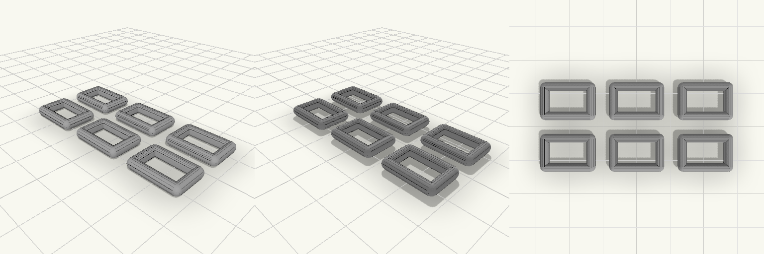
SlotKeeper — Rectangular Velcro Strap Ring
SlotKeeper is a compact rectangular slot ring for velcro straps, built as a single 3 mm-thick keeper/loop. The 11 × 6 mm internal opening gives webbing a clean pass-through, while the 16 × 11 mm outer body and 2.5 mm walls keep the ring solid and simple to print. The edges carry the design: a 1.4 mm rounding on the outside and a 1.0 mm flare around the top and bottom of the opening give it a soft, pill-like profile, so nothing sharp touches the strap on either face. The opening itself is a clean, square-cornered 11 × 6 mm rectangle, so the webbing sits flat right into the corners. The file comes as a set of six identical keepers arranged in a 3 × 2 grid on the plate, so a batch of straps can be kitted out in one print. The whole grid covers 56 × 26 mm of bed at 3 mm tall. Dimensions Internal slot: 11 × 6 mm at its narrowest point Outer body (each keeper): 16 × 11 mm Overall thickness: 3 mm Wall thickness: 2.5 mm Outer edge rounding: 1.4 mm Opening edge flare: 1.0 mm Print-plate footprint (6-up grid): 56 × 26 mm Features Six keepers per print, laid out 3 × 2 and separated for individual use Soft, pill-like profile instead of a boxy ring Rounded outer edges all round, with the opening edges flared to match A narrow flat band remains on the top and bottom faces — enough to sit flat, little enough that no hard corner meets the webbing Square inner corners for a true 11 × 6 mm rectangular slot Thick 2.5 mm walls for a strong loop Print notes Each keeper prints as one solid piece with no extra assembly; the six copies are already spaced on the plate. The 2.5 mm walls and 3 mm overall thickness give a sturdy loop, and the softened profiles mean no sharp edges come off the plate against the strap.
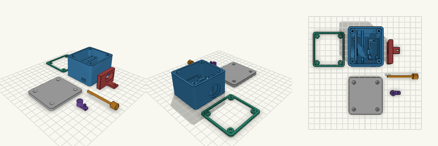
sidways and 2mm indent final cable lock sideways servo
Servo-operated cable lock for a paddleboard rental system, printed in five rigid parts plus a flat TPU gasket. A sliding keyhole plate retains a round cable terminal. A servo arm moves the plate to the release position, where it stops against a wall block. Specs Gasket: 1.5 mm flat TPU, matches the housing rim, with pads and 3.4 mm holes for the four cover screw posts Gasket print: flat on the bed, TPU 95A, slow speed, 100% infill or 4+ walls Terminal head: 10 mm round, 7 mm locking slot, 14 mm release hole Servo: 9 g micro servo, lowered into a floor indent, lead exits the -Y wall Rigid parts: PETG or ASA, 4-6 walls Sealing: the gasket reduces water entry at the cover joint. It is not tested and the lock is not claimed to be waterproof Not load-tested
T型槽导轨底座 滑块卡边
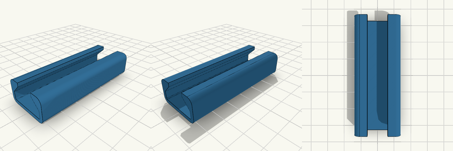
滑块往上一提就脱槽、侧向还晃?这个底座用 T 型槽把滑块的卡边扣在槽里,只能沿槽长方向滑动。 关键尺寸 外形:24.8 × 64 × 13.4 mm,两端开口,滑块从端部推入 宽槽腔:20.8 × 4.4 mm(卡边 20 × 4 mm,单边留 0.4 mm 间隙) 窄口:10.8 mm 宽,上缘压边厚 2 mm 壁厚 2 mm,底板 2 mm,外侧和槽内转角均为圆角 打印 开口朝上平放,无需支撑 宽腔顶部做成 45° 斜面,避免悬空桥接;滑块卡边上沿需做同样的 45° 倒角 PLA 即可
Flat Slider Block with Side Rails
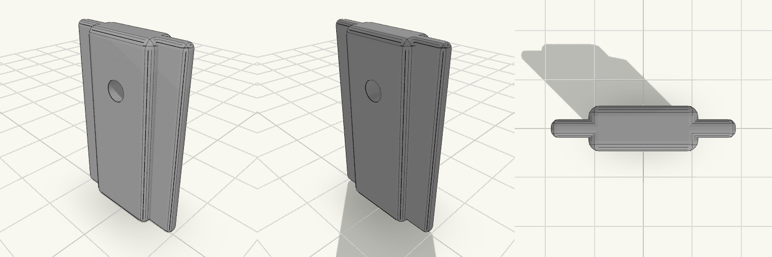
A flat slider block with two side rails that ride in a slot, so it moves up and down in a straight line. A 3.2 mm hole passes through the 5 mm thick body for a pin or linkage connection. Body: 12 × 5 × 30 mm with rounded edges Side rails: 20 mm overall width, 2 mm thick, centred on the body Hole: 3.2 mm diameter, through the thickness, 22 mm up from the base Prints standing on its end with no supports The rails sit at mid-thickness, so the slot needs a matching 2 mm groove plus clearance of about 0.3 mm per side.