220mm Vented Wrist Extension Splint
Created 2 months ago
Description
A two-piece rigid wrist splint configured to enforce a 15-degree extension, supporting the natural arch of the hand for typing during RSI flare-ups. The primary structure relies on a heavy volar spine and moulded palm bar to restrict flexion, while the dorsal cover is relieved by a staggered cylinder lattice to manage thermal buildup over long sessions.
Specifications
- Size: Medium (220mm overall length)
- Extension Angle: 15 degrees
- Restraint: Six integrated 25mm strap slots (three per side)
- Ventilation: 10mm staggered lattice array on the dorsal shell
- Clearance: 6mm split between halves for strap tensioning
Images
More like this
Explore more in Desk & Tech →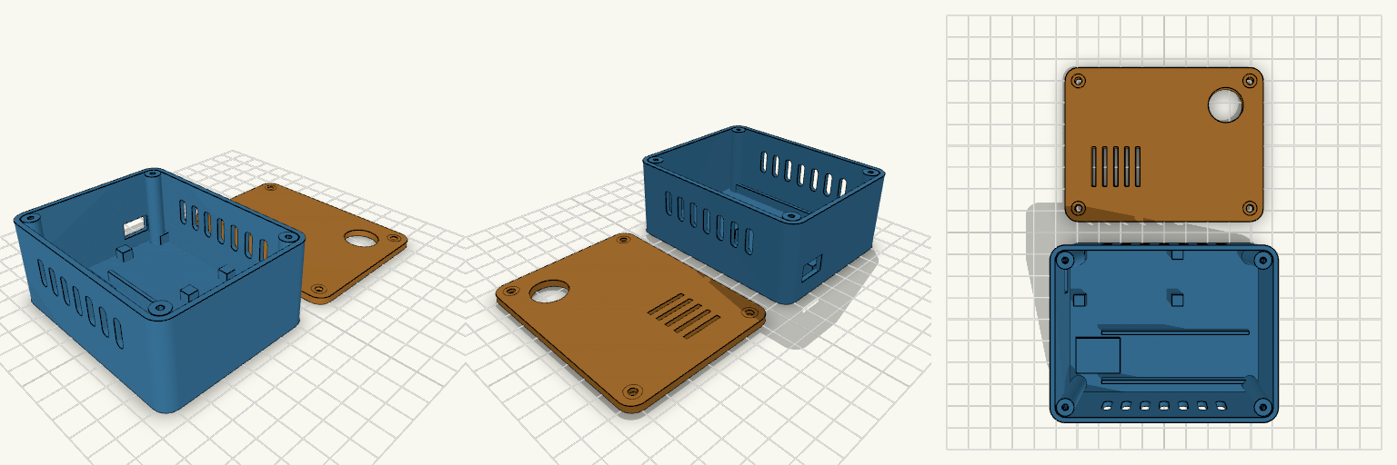
SilentSOS Two-Piece Electronics Enclosure
A 90 × 70 × 40 mm two-piece enclosure for an ESP8266 NodeMCU SOS alert device: a 37 mm tall base with 2 mm walls and a separate 3 mm lid, with 6 mm rounded vertical corners. The lid is printed flat and fastens with four M3 screws into corner bosses. Remix hooks Component mounting: no hole positions were guessed. The NodeMCU sits on four 5 mm locating pads at the board corners (49 × 26 mm area, nb, nbc). Once measured, add real standoffs in extraposts as [x, y] pairs and set post_pilot. Battery bay: two 1.5 mm rails 22 mm apart hold a cell of about 18 mm diameter, 65 mm long. Move or space them for other cells. DC-DC zone: a low 20 × 16 mm pad, free to move or resize. USB opening: 13 × 8 mm in the short wall, aligned to the NodeMCU position. SOS button: 16 mm hole in the lid (btnd, btnpos). Ventilation: seven slots in each long wall plus five slots in the lid. Screws: 2.6 mm pilots in the bosses, 3.4 mm countersunk lid holes. Pairs well with heat-set inserts in the bosses, or a gasket strip for a dust-resistant fit. Export base and lid as separate STLs by rendering each module alone.
Pizza Spinner Fidget Print Set
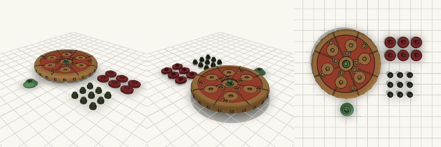
What it's for A pizza-shaped fidget spinner that turns freely on a central hub. The pepperoni and olives are separate snap-on toppings, each with a split pin that clicks into a socket. Each topping also has a marked seat in the sauce, so the right position is easy to find. Dimensions Pizza: 62 mm diameter, bumpy crust, sauce with slice grooves Hub: protrudes on both sides, 0.5 mm clearance to the pizza 6 pepperoni: 10 mm, seat 10.6 mm 9 olives: 5 mm, seat 5.6 mm Pins: 3.4 mm split pins into 3.5 mm sockets Print notes Toppings print upside down, pin facing up, no supports needed. Olives are small; a standard 0.4 mm nozzle will soften the details. Pieces print in separate colours and can be mixed freely. Remix ideas Add mushrooms or peppers using the same pin and seat. Change the topping layout by moving the seat positions. Make the hub longer for a better grip.
Perch — Clamp-On Headphone Holder
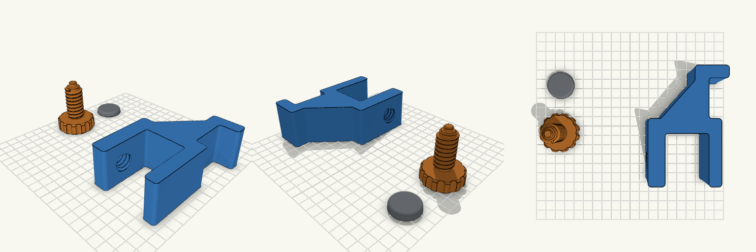
Perch is a three-piece desk-edge headphone holder: a main body with hook and clamp jaws, a separate threaded adjustment screw with a large scalloped knob, and a loose pressure pad. Nothing is joined or printed in place, so the parts are laid out separately and assembled by hand after printing. Features Clamp range of 15–35 mm, suited to a 20 mm desk Internal thread in the lower jaw with 0.4 mm radial clearance for the 18 mm, 4 mm-pitch screw 40 mm knob with scalloped grip Pad snaps onto an 8 mm peg at the screw tip and spins freely Reinforced hook with gusset and rounded lip Print notes Body on its side, screw knob-down, pad flat PLA, 0.4 mm nozzle, 0.20 mm layers, 4 walls No supports expected Assembly Thread the screw up through the lower jaw from below, then press the pad onto the peg. Set the source's mode value to 1, 2 or 3 to export each part individually.
Octobay — 5.25" to 3.5" Drive Cage
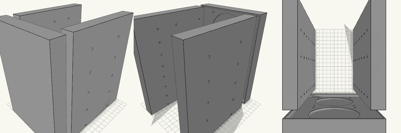
Octobay turns a five-bay stack of half-height 5.25" slots into room for eight 3.5" drives, and adds a 25 mm front cage that carries two 92 mm fans. The outer side faces take M3 heat-set inserts, so the whole cage screws into the case's 5.25" rails instead of resting on them. Everything is one printed part: the drive stack, the side mounting blocks and the fan cage print as a single body. Because the fans close off the front, drives now load from the back. The fan cavity behind the grille is hollow, so air still passes through to the drive stack. Dimensions Overall: 145 mm wide × 197.5 mm deep × 205.5 mm tall Fits: five half-height 5.25" bays Holds: eight 3.5" drives, stacked vertically Drive channel: 102.6 mm wide — 1 mm of play around a 101.6 mm drive Mounting 20 insert holes, 10 per side, for M3 heat-set inserts — 4.2 mm across and 6 mm deep Two insert holes per bay, at 41.3 and 117.5 mm from the front, 6.35 mm above each bay floor Solid blocks sit behind each hole to give the inserts something to bite into Three M3 screw holes per side per drive, at 14, 76.6 and 117.6 mm from the front Cross ribs sit clear of the screw holes so a screwdriver can reach every fastener Fan cage Two 92 mm fans, stacked vertically on the 25 mm front section 88 mm fan openings with 4.4 mm screw holes on the standard 82.5 mm square pattern Hollow cavity behind the fans feeds air to the drive channels Print notes Drive channels are open at the back, top and bottom, and the gaps between the inner and outer side walls are open for cable routing. Screw and insert positions and the 205.5 mm height follow common 5.25" bay standards; they have not been checked against a specific case, so measure your bay rails and drives before printing.
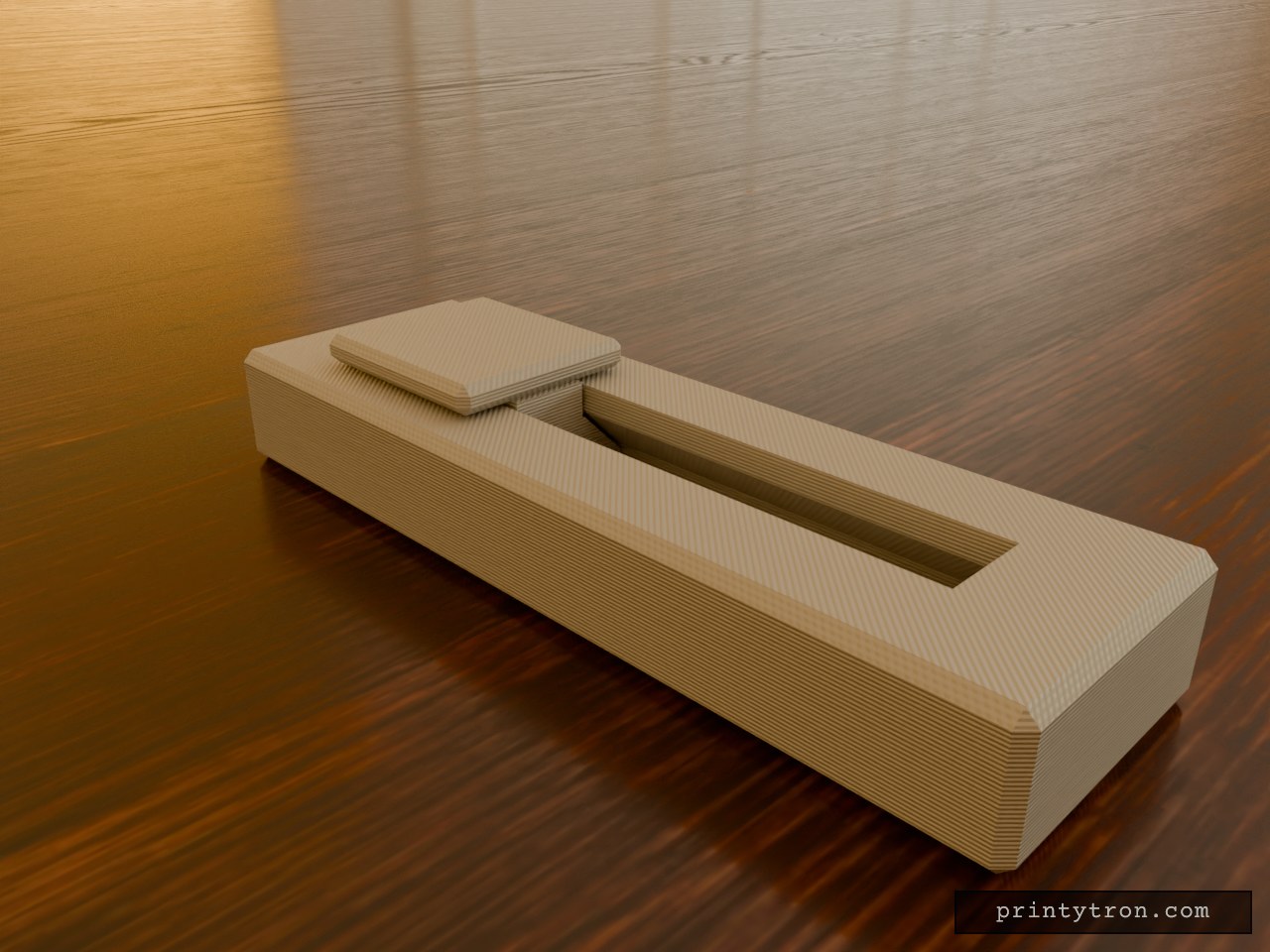
Fidget Slider Toy, Captive Print-in-Place
A fidget slider that prints already assembled, so there is no loose weight to lose and nothing to glue. The slider is captured in an enclosed dovetail track and cannot fall out. It runs 40 mm end to end and clicks at each stop instead of rolling freely. What it does Slides back and forth along a closed track in an 80 x 25 mm body. A small bump on the track floor at each end of travel drops into a dimple under the slider and gives the click. The dovetail profile holds the slider down, so it cannot lift out of the rails. Numbers that matter Body: 80 x 25 x 11 mm, with the slider top reaching 14 mm. Slider: 20 mm long, 18 mm wide cap. Travel: 40 mm. Clearance between slider and track: 0.4 mm per side. This is what lets it move after printing. Click bump: about 0.6 mm of interference against the 0.4 mm gap. Reduce the bump height if it feels too stiff. Printing Print flat, body base down, with no supports needed inside the track. Use a well-tuned printer. A 0.4 mm gap fuses easily if the flow is too high. After printing, work the slider back and forth a few times to break any thin bridging between the slider and the rails. Two colours show as separate parts in the preview, but the print is one job.
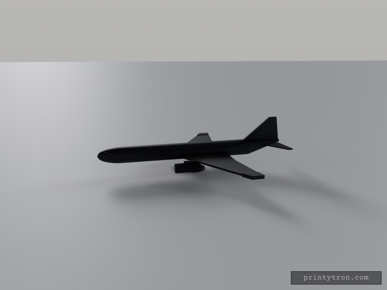
Virgin-Rot-Weiß: Boeing 777 Standmodell
Virgin-Rot auf Weiß: Der weiße Rumpf mit rotem Bauchstreifen, das rote, gepfeilte Seitenleitwerk und die roten Triebwerke an den Flügeln bringen den Virgin-Atlantic-Look auf den Tisch. Die Boeing 777 steht als Standmodell mit gewölbter Nase, hochgezogenem Heck, blauen Fensterreihen und schrägen Cockpitscheiben; auf beiden Rumpfseiten steht „virgin atlantic“ in roter Schrift. Einläufe und Ständer sind weiß gehalten. Was dran ist: Maßstab etwa 1:320 – rund 230 mm lang und 200 mm Spannweite Gepfeilte Flügel mit roten Spitzen, Triebwerke an Pylonen mit weißen Einläufen Fensterreihen und Cockpitfenster in Blau, roter Bauchstreifen und Schriftzug „virgin atlantic“ Kein Fahrwerk – ein weißer Ständer trägt das Modell Farben getrennt wählbar: Weiß für Rumpf, Flügel, Höhenleitwerk, Einläufe und Ständer; Rot für Leitwerk, Triebwerke, Spitzen, Streifen und Schrift; Blau für die Fenster