3/4" to 1/2" Reducer Spout
Created 1 months ago
Description
A custom utility reducer built to bridge a 3/4” threaded plumbing fitting (like a standard SharkBite threaded end) down to a narrow spout.
Features of this adapter:
- Base Interface: 3/4" female straight pipe threads (14 TPI) intended to accept a standard plumbing fitting. An O-ring or plenty of thread tape is recommended to ensure a watertight seal since 3D-printed threads don't compress quite like brass.
- Transition: A sturdy 15mm tapered funnel to keep the fluid flow smooth.
- Spout: A 2-inch (50.8mm) long extension with a rigid 1/2-inch (12.7mm) outer diameter, chamfered at the tip for easy hose insertion.
Photos
Technical views
More like this
Explore more in Home & Fixtures →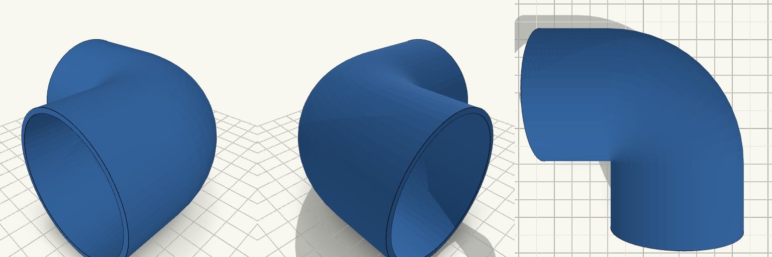
Compact 90-Degree Elbow Pipe
What it's for A highly compact 90-degree pipe elbow designed to route fluids or air in tight spaces. Instead of a long, sweeping plumbing radius, this model pulls the corner in as tight as physically possible—bringing the outer inner corner to a sharp point while maintaining a 2 mm smooth transitional radius on the interior flow path to prevent sharp turbulence. Dimensions Outer Diameter: 60 mm Inner Diameter: 56 mm Wall Thickness: Constant 2 mm Straight Sections: 30 mm on each end Print notes Orient the pipe flat on its side (as positioned by default) to print entirely without supports. A brim may be helpful depending on bed adhesion, though the large flat contact patch is usually sufficient.
jet reducer nipp
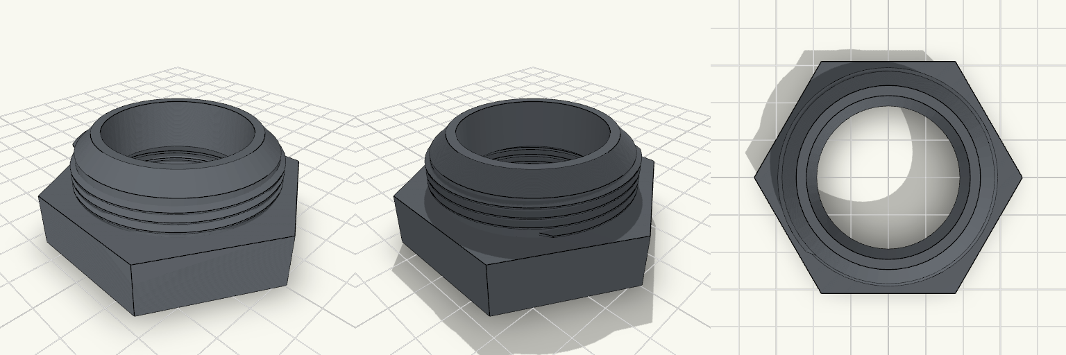
Mismatched pipe threads stop a plumbing job dead in its tracks. Instead of chaining together three different brass adapters and hoping they don't leak, this straight-shots a 1 1/4" male line into a 1 3/4" female fitting. The threads are cut straight (NPS style) with FDM clearance built in, so you will need a healthy wrap of Teflon tape to force a watertight seal. Total Length: 3 inches (76.2 mm) Wrench Flats: 60 mm across, giving a solid grip for a large adjustable spanner. Bore: 32 mm internal channel. Threads: ~11.5 TPI pitch, heavily offset to prevent layer-binding on FDM prints.

Smart Duplex Sconce Plate
An oversized, deep-shell wall plate for a standard US duplex outlet, built to house a Raspberry Pi Zero W and up-and-down sconce lighting. Pi Zero Mount: Integrated standoffs (58x23mm spacing) for M2.5 screws, tucked beside the receptacle. Lighting Control: 5.5mm face cutout for an ambient light sensor. LED Bays: Top and bottom mounting blocks with flush cutouts for dual-directional LED strips. Clearance: 14mm overall depth clears standard hardware while providing internal routing space.
30mm Fluted Drawer Knob
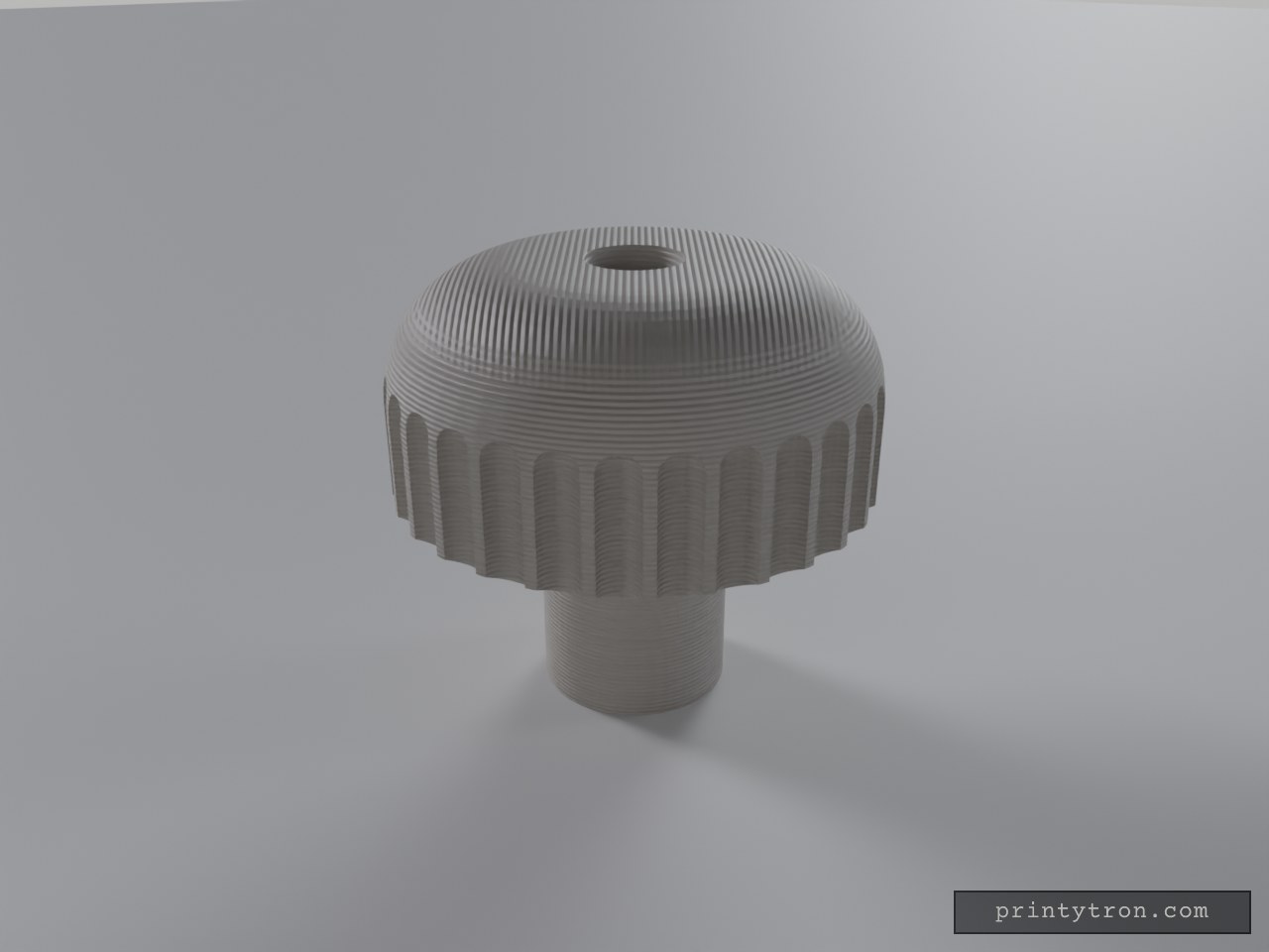
A mushroom-style drawer knob with a straight-fluted grip ring. Designed for environments where hands may be wet, the flutes provide mechanical grip without the complex recesses of a diamond knurl that trap moisture. The part includes a central clearance hole for standard M4 mounting screws. Specifications Cap Dimensions: 30 mm diameter, 18 mm tall Stem Dimensions: 12 mm diameter, 10 mm length Total Standoff: 28 mm Mounting: M4 clearance through-hole (4.5 mm diameter) Grip Feature: 30 vertical flutes
Płyta 18mm Nóżka Kątowa 150mm
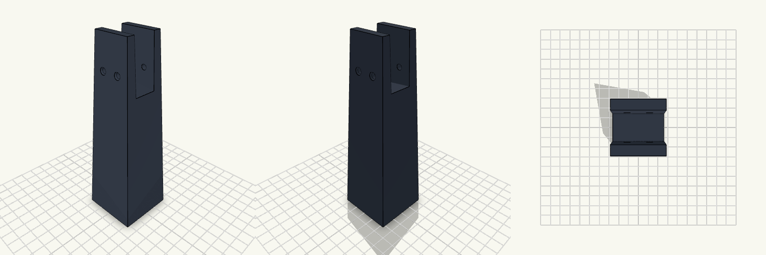
Nóżka oporowa pod standardową płytę meblową 18 mm. Gniazdo ma 18,6 mm szerokości, co daje luz roboczy pozwalający wsunąć krawędź płyty bez rzeźbienia materiału, z pełnym prześwitem na wylot (brak ścianek czołowych). Dno kanału opada pod kątem, dając około 3 mm różnicy wysokości na 30-milimetrowym odcinku chwytu. Podstawa została rozszerzona do 45x45 mm – przy 150 mm całkowitej wysokości prosty słupek nie utrzymałby obciążeń bocznych. Wymiary montażowe Kanał U: 18,6 mm szerokości, 40 mm głębokości (w najpłytszym miejscu). Mocowanie: Dwa otwory przelotowe 4,5 mm z fazowaniem pod wkręty z łbem stożkowym, rozstaw 14 mm. Wysokość całkowita: 150 mm. Kąt dna: Spadek 3 mm na 30 mm długości profilu. Pasuje do gołych płyt 18 mm (wiórowa, MDF, sklejka). Nie wciśniesz w to płyty 22 mm, a z płytą 16 mm wkręty po obu stronach będą musiały ściągnąć ścianki kanału, co grozi pęknięciem wydruku. Przed drukiem upewnij się, że 3 mm spadek na dnie to właściwy kąt dla twojej zabudowy.
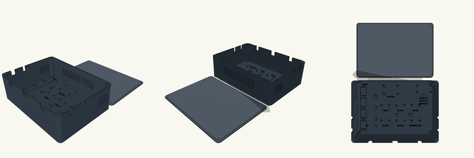
280mm Irrigation Controller Enclosure
A rigid 280 × 200 × 90 mm printed enclosure designed specifically for an ESP32-based multi-zone plant irrigation controller. The layout divides the internal volume into three distinct areas: high-current power distribution on the left, six MOSFET drivers in the center, and the low-voltage microcontroller logic on the right. An extra-wide central cable channel runs between the two rows of MOSFETs, and all high-traffic access areas—like screw terminals and adjustment dials—have generous working clearances. The outer walls feature deep U-slots for cables, cut from the top edge so the main flat lid traps them cleanly in place without relying on separate cable glands. Internal Layout details Zone A (Power): Mounts for a 56×35 mm DC-DC buck converter, a friction-fit bracket stack for four WAGO 221-415 lever connectors, and a C-clip for an inline 5A barrel fuse. Zone B (Switching): Two rows of custom mounts for six 35×32 mm MOSFET boards. Each uses exactly two diagonal standoffs to leave maximum free space around the terminals. Zone C (Control): Stand-offs for an ESP32 NodeMCU, with a dedicated USB-C opening aligned in the external right-hand wall. Structure: Embossed floor labels mark all hookup zones. Cable tie bridges are scattered throughout the base for organization, and vertical ventilation slots flank the rear and sides. Uses four M3 screws driven directly into heavy internal corner bosses to seal the lid.