Curved Ø42 Pipe with Two Ø38 Branches
Created today
Description
A hollow pipe that bends 70° along a 70 mm centreline and then splits into two diverging branches. The main bore is Ø42 with a 3 mm wall (Ø48 outside), giving a bend radius of roughly 57 mm. Where the bend meets the branches, the junction is stretched into a long egg-shaped blend — about 76 mm along the flow and 62 mm across — so the outside runs smoothly from the bend into each branch and the Ø42 bore narrows gradually into the two Ø33 bores, with no step or flat seam at the joint.
On the print plate the two smaller branches lie flat and fan out sideways, side by side at ±17°, while the big curved pipe rises from them and bends upward, leaving its Ø42 inlet at the top of the bend rather than on the plate. The branches leave from either side of the junction rather than a single shared point, and the gap between them narrows quickly toward the blend, so only the outer stretch of each pipe stays clear for a hose — about 16 mm of clear space at the open ends, on centres roughly 56 mm apart.
The whole part prints as a single hollow form with the branches already joined to the curve — no separate pieces or assembly. As it sits on the plate it measures about 92.6 × 141.2 mm with a height of about 69.9 mm, so check that against your bed before slicing. Keep the internal passages free of supports or bridging material so the flow stays unrestricted.
- Main bore: Ø42 inner, Ø48 outer, 3 mm wall
- Bend: 70° over a 70 mm centreline (≈57 mm radius), rising upward
- Branches: two, at ±17°, Ø38 outer, Ø33 inner (≈2.5 mm wall), 62 mm long, lying flat and fanning sideways
- Junction: stretched egg-shaped blend, approx. 76 mm along the flow and 62 mm across, feeding both branch bores without a step
- Branch spacing: ≈56 mm centre to centre, ≈16 mm clear at the open ends
- Footprint on the plate: approx. 92.6 × 141.2 mm, height approx. 69.9 mm
Use it where a single round duct has to turn a corner and then divide into two angled outlets of a smaller diameter that each take a hose.
Images
More like this
Explore more in Home & Fixtures →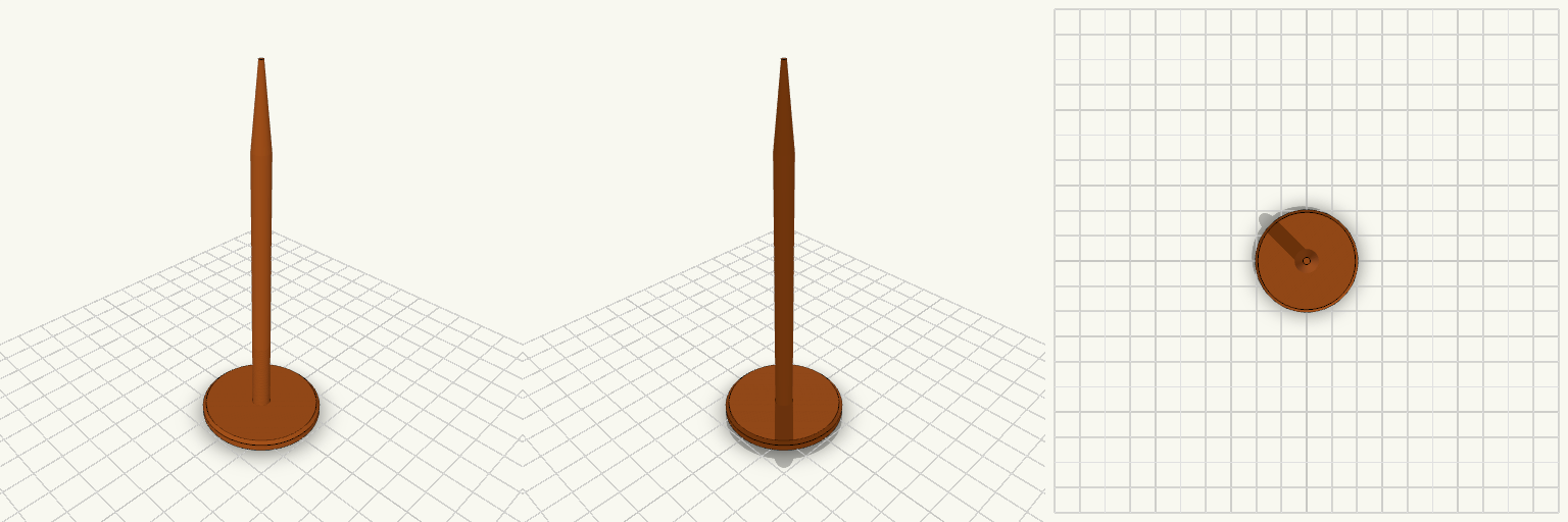
Charging Station Marker Nail
A ground marker nail for holding the position of a robot mower charging station while the charger is stored for the season. It is pushed into the soil where the charger's screw sits in summer. The nail has a wide, flat 40 mm head that stays visible at ground level, a slim 6 mm round shaft, and a tapered point for easy insertion. It prints head-down, so no supports are needed. Head: 40 mm diameter, 4 mm thick, chamfered edge Shaft: 6 mm diameter, about 90 mm long Tip: tapers to a point over 25 mm Overall length: about 119 mm Prints without supports
Perilla de estufa de repuesto con vástago reforzado
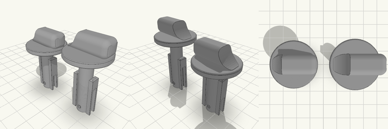
La perilla de la estufa que gira en falso o se parte deja el fuego sin control; esta perilla de repuesto se calza sobre el caño de gas y se traba con pasador, con el pulgar recortado al contorno del collar y todos los bordes del agarre redondeados para girar sin engancharse. La placa trae dos perillas: la original y una copia con vástago de 35 mm para cambiar el largo según la estufa. Cotas que deciden el calce Dos perillas en la misma placa: la original mide 41,5 mm de alto total (12 mm de cabeza + 29,5 mm de vástago); la copia mide 47 mm de alto total (12 mm de cabeza + 35 mm de vástago). En la placa ocupan 58 × 26 × 47 mm. Vástago: 8 mm de diámetro exterior, con dos aletas planas de refuerzo de 24 mm a los lados; en la copia, las aletas quedan en la zona de la punta. Vástago hueco: orificio de 5,5 mm de diámetro, abierto en la punta. En la original llega a 26 mm de profundidad y queda ciego en los últimos 3,5 mm hacia la cabeza, con paredes de aproximadamente 1,25 mm; la copia mantiene el mismo orificio de 5,5 mm. Agujero pasante: 2,2 mm de diámetro, horizontal, con el centro a 3,5 mm del extremo inferior; cruza la cavidad del vástago, así que la chaveta atraviesa el caño de gas. Endija: 3 mm de ancho, abierta en la punta; va a 90° del agujero del pasador, atraviesa el vástago y corta también las aletas laterales, dejando el extremo dividido en dos mitades flexibles. En la original llega a 11 mm; en la copia llega a 17,5 mm, la mitad de su vástago. Cabeza: collar de 26 mm de diámetro por 3 mm de alto; el pulgar mide 26 mm de ancho, 10 mm de grosor y 9 mm de alto sobre el collar, ya no pasa el contorno del collar, es plano de un lado y baja curvo del otro. Todas las aristas del pulgar tienen 3 mm de radio; los bordes del collar tienen 0,8 mm. Cada perilla se imprime de una sola pieza; la endija no separa el modelo, solo deja flexibles las dos mitades del extremo. El acabado negro mate sale del filamento que elijas, no de la geometría. Antes de imprimir, mide el diámetro del caño de gas y el del pasador: el hueco del vástago y el agujero pasante son las dos cotas que no perdonan, y si no coinciden es mejor ajustarlas antes de gastar material.
Broom Stick Hook for 25.3 mm Handles
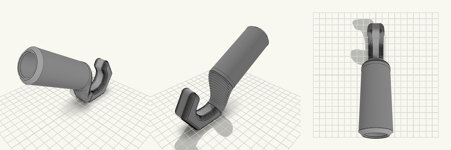
What it's for A one-piece hook for the end of a metal broom stick. The sleeve fits over a 25.3 mm handle with a tight friction fit, and the inline half-hexagon hook rises from the top of the sleeve. Its centre sits on the stick axis, so a coat rack bar hangs in line with the handle and the broom hangs straight. The inside of the hexagon is 31 mm flat to flat for a rack rail up to 27 mm, with a smooth continuous inner path. The beam is 15 mm thick and 22 mm wide, with a 6 mm radius on its long edges and rounded outside corners. Between sleeve and hook, the sleeve's round outer radius eases into the beam's rounded section over about 34 mm, starting 8 mm below the sleeve's top edge and shifting onto the beam's offset line, so there is no flat shelf or sharp edge along the transition. The inside corners carry a 14 mm radius. There is no screw hole; use friction, glue, or a wrap of tape if the fit is loose. Inline hook at the end of the stick Sleeve for a 25.3 mm metal broom handle 25.5 mm bore for a tight friction fit Half-hexagon hook centred on the stick axis 31 mm inside opening for a rack rail up to 27 mm Rounded beam and a blended, edge-free sleeve-to-hook transition No screw hole; use friction, glue, or tape if needed Dimensions Overall size as oriented for printing: 38 × 147.6 × 106 mm Broom sleeve bore: 25.5 mm for a 25.3 mm handle Hook opening: 31 mm flat to flat inside, for a rack rail up to 27 mm Hook beam: 22 mm wide, 15 mm thick, 6 mm edge radius Hook centre: about 32 mm above the sleeve, on the stick axis Print notes The part rests on the angled hexagon face next to the flat outer face — the next face round from the opening — so it sits tilted about 30° from flat and the opening leans over rather than pointing straight up. The sleeve end angles up off the plate, which keeps the overhang under it smaller than a flat-face stance would, but that underside will likely still want a little support. Flat contact face is narrow: add a brim for grip The hook arch itself should print cleanly This design has not been test-printed For a hanging metal broom, use 5 or more walls and about 40% gyroid infill Check the neck around the hook gap after printing, since it carries the hanging load Test the friction fit on the handle before use Remix ideas Resize the 25.5 mm sleeve bore for other handle diameters Change the 31 mm hook opening for a different rail size Adjust the beam width or edge rounding for a different balance of comfort and stiffness Add a grip band or clamping collar for heavier handled tools
Keil für Echo Show 5 mit 20 mm Rückenhöhe
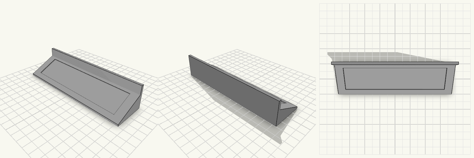
Der Keil hebt den hinteren Teil des Echo Show 5 an, damit er nicht mehr schief steht, sondern nach vorn geneigt sitzt. Er ist 148 mm breit und 40 mm tief; die Schräge steigt von 2 mm an der Vorderkante auf 20,5 mm hinten an. Am hinteren Ende sitzt zusätzlich eine 3 mm dicke Kante über die ganze Breite, die rund 10 mm über die Schräge hinausragt und das Gerät am Zurückkippen hindert – an der höchsten Stelle misst der Keil damit 30,5 mm. In die Schräge ist mittig eine Vertiefung von 128 × 30 mm eingelassen, 1,5 mm tief und parallel zur Schräge, in der die Standfläche des Lautsprechers liegt und nicht wegrutscht. Der Keil lässt sich unter den Lautsprecher schieben und passt auch unter eine Schrankhalterung, wenn dort mehr Neigung gewünscht ist. Remix-Hooks Breite (148 mm): eine Messung am Gerät, keine Schätzung mehr – wer die Auflage über die volle Standfläche laufen lassen will, ändert hier nichts; wer schmaler baut, sollte die Vertiefung im gleichen Verhältnis mitziehen. Tiefe (40 mm): bestimmt, wie weit der Keil unter dem Gerät hervorschaut. Weniger Tiefe heißt weniger Auflagefläche und eine kürzere Vertiefung, mehr Tiefe ergibt eine flachere Schräge. Rückenhöhe (20,5 mm) und Vorderkante (2 mm): das eigentliche Neigungspaar. Beide Werte zusammen ändern, sonst wird der Winkel steiler oder flacher als gewollt. Rutschkante (3 mm dick, ca. 10 mm über der Schräge, Gesamthöhe 30,5 mm): so niedrig wie möglich halten, damit sie hinter dem Gerät nicht aufträgt; eine Version mit zwei seitlichen Stegen statt einer durchgehenden Kante ist die naheliegende Variante. Vertiefung (128 × 30 mm, 1,5 mm tief): bewusst ein einfaches Rechteck, weil die genaue Form der Geräteunterseite nicht vermessen ist. Wer die Standfläche kennt, passt Länge, Breite und Tiefe an oder ersetzt das Rechteck durch eine gerundete Mulde. Oberfläche: eine geriffelte oder gummierte Auflage in der Vertiefung ist die einfachste Variante gegen Verrutschen; aktuell ist die Fläche glatt. Kombination: der Keil lässt sich mit einer Unterbauhalterung oder einer einfachen Schale kombinieren, wenn das Gerät gleichzeitig hängen und geneigt stehen soll. Vor dem Druck die Standfläche des eigenen Geräts prüfen – Breite und Tiefe der Vertiefung sind geschätzt, nicht nachgemessen.
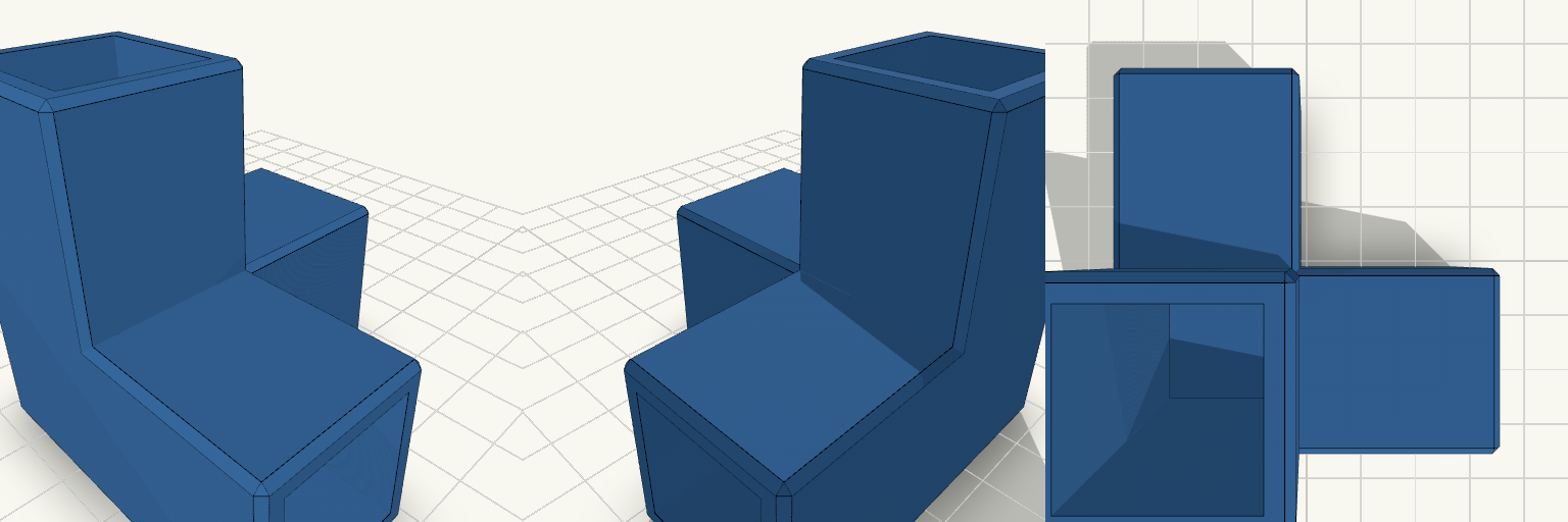
Trícoro — Cantoneira para Tubo Quadrado 20 mm
Trícoro é uma cantoneira de canto pensada para montar estruturas com tubo quadrado de 20 mm. Os três encaixes partem do mesmo canto — dois laterais, em X e Y, e um vertical em Z — com 90° entre si, permitindo formar cantos e arranques de estrutura com uma única peça. A cavidade de 20,4 mm deixa 0,4 mm de folga por encaixe, e a parede de 3 mm dá rigidez aos braços de 55 mm. A base fica plana, pronta para assentar na mesa de impressão, e a peça imprime como uma só parte. Dimensões Medida total: 55 × 55 × 55 mm Comprimento de cada braço: 55 mm Cavidade por encaixe: 20,4 mm (para tubo quadrado de 20 mm) Folga: 0,4 mm Espessura da parede: 3 mm Encaixes Dois encaixes laterais, nos eixos X e Y Um encaixe vertical, no eixo Z Todos a 90° entre si, partindo do mesmo canto Notas de impressão A base fica plana em z = 0. Imprime como peça única; não requer montagem.
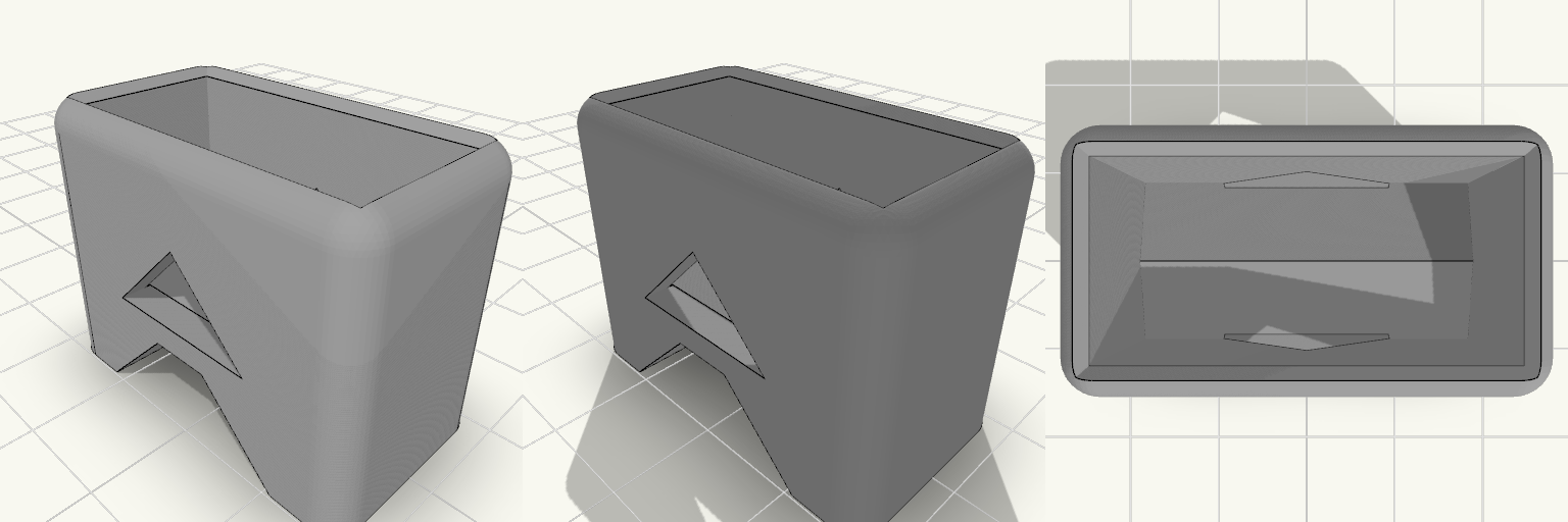
Draining Sleeve Foot for a Laundry Hamper Leg
The wood at the bottom of a hamper leg is the first thing to go: it stands in whatever puddle the bathroom floor collects, drinks it up, and goes soft until the basket slumps and rocks. This sleeve slides onto the end of one rectangular wooden leg, holds the wood about 9 mm clear of the floor, and slopes its pocket floor so splash water runs out the sides instead of sitting in there against the wood. What it does Pocket: 31 × 15 mm inside, sized exactly to the leg with no added play — that measurement already accounts for clearance. 15 mm deep at its shallowest point, the centre ridge, and deeper toward the sides where the floor falls away. Stand-off: a single arched cut runs the full depth of the underside, leaving two flat feet that hold the leg about 9 mm off the floor. Overall height is about 27 mm. Drainage: the pocket floor is a shallow ridge sloping down to both long sides, with one 16 mm slot through each long wall at the low edge. Water leaves sideways, and the slot bottoms sit 10.5 mm above the floor, so no opening rests in the wet. Each slot is pointed at the top rather than flat-roofed, which is what lets it print clean. Shape: 1.2 mm chamfer at the opening to get it started over the wood, 3 mm rounding on the vertical and top edges so it doesn't snag a mop or a bare toe. The bottom edges are left sharp so they sit flat on the bed. Printing it Print in PETG with the sleeve opening facing up and the two feet on the bed — no supports anywhere. The arch sides are 45°, so the only bridge is the flat strip about 6 mm across the roof of the arch. The finished part measures roughly 36 × 20 × 27.2 mm, walls 2.5 mm thick. A plain matte finish in white, grey or black sits well in a bathroom. A zero-clearance pocket is tight in PETG. Check the leg with calipers before printing if the wood looks swollen or tapered — if it won't slide on, the pocket wants a few tenths opening up.