8-Camion
Created 1 months ago
Description
A truck missing one wheel is just a seesaw that scratches the floorboards. Stripped hex hubs or worn treads usually end a run early; this is the right-side replacement to get it rolling flat again. The tread channels are cut at a 20-degree angle to specifically mirror the left side, keeping the traction profile symmetrical.
Fitment and Print Details
- Outer Diameter: 78 mm
- Width: 26 mm
- Drive Interface: Standard 12 mm RC hex socket (6 mm deep)
- Axle Clearance: 5.2 mm bore, clearing standard 5 mm axles.
- Printing: Drop it flat on the inner face (the hex side). No supports needed; the outer rim inset chamfers cleanly. Needs dense infill around the hub to prevent the hex from rounding out under torque.
Images
More like this
Explore more in Automotive, RC & Hobby →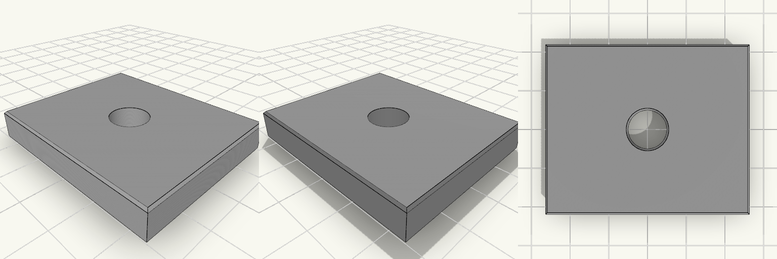
Elliptical Pedal Center Insert
A 48 × 40 × 7 mm replacement insert for the broken center of an elliptical trainer pedal. Flat top, 10 mm through-hole, 20 mm full-height boss, and a ribbed underside. Remix hooks Footprint (48 × 40 mm): the main value to tune to the pedal pocket; rim, ribs and diagonals follow it. Top edge chamfer (0.5 mm): set to 0 for a fully tight seam. Hole (10 mm) and boss (20 mm): change for a different axle or bolt; a wider boss adds strength. Underside depth (3 mm): rim and ribs can be taller or thinner, with the top plate at 4 mm. Pairs with: countersunk screws or adhesive through the boss area.
Triple Socket Adapter Floor Cradle
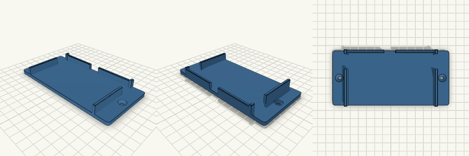
What it's for A one-piece floor cradle that holds a triple 12V socket adapter horizontally under a dashboard. The front and top stay open, so the sockets and power switches remain reachable, and side windows keep the side USB ports clear. Dimensions Adapter: 100.4 x 60.85 x 31.72 mm, about 1 mm clearance Side walls: 3 mm thick, 14 mm tall Side windows: 18 mm long, centred 51.38 mm from the front (plus 1 mm clearance) Back lip: 12 mm tall with reinforced corners Mounting ears: 16 mm each end, countersunk screw holes Remix ideas Change the window length to fit a different USB port. Add a third screw hole at the back. Lengthen the ears for wider mounting.
Technic Plate 2x4 With Holes, Set of 6
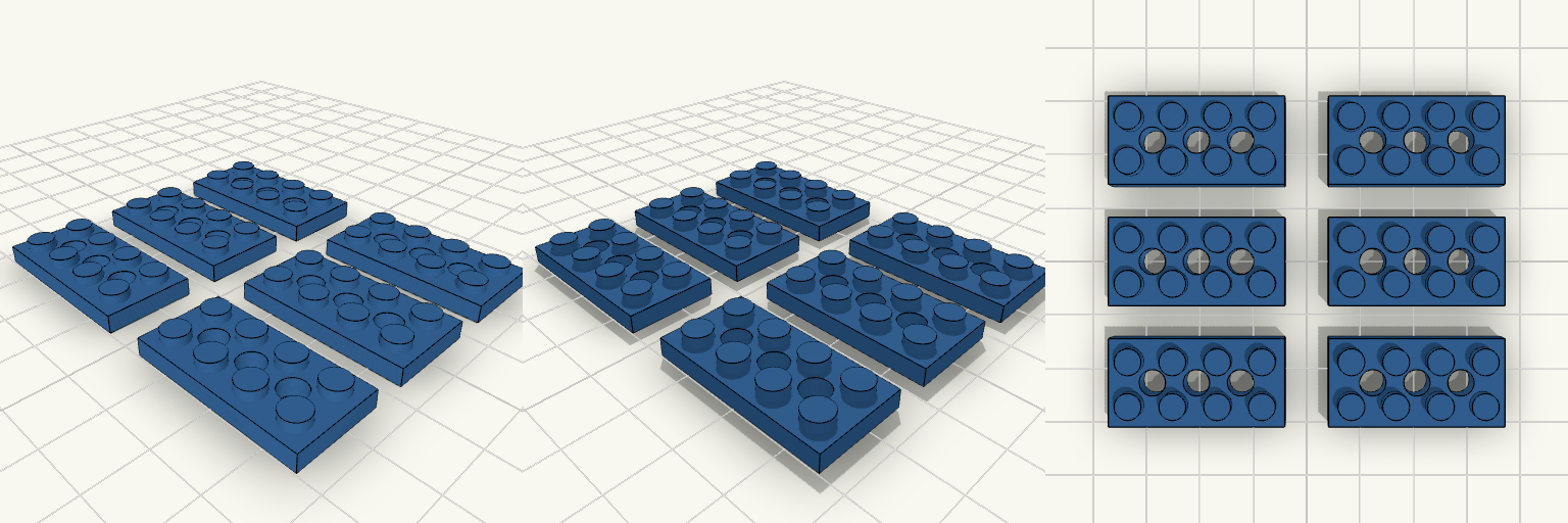
A 2x4 plate with no way to pass a Technic pin or axle through it is a dead end in a studless build. This plate has three holes on the centre line, so pins and axles go straight through. Six are laid out flat for one print run. Key numbers Plate: 32 x 16 mm, 3.2 mm thick, studs on 8 mm pitch Studs: 4.8 mm diameter, 1.8 mm tall Holes: three, 4.8 mm diameter, on the centre line, 8 mm apart Print: flat, no supports, 0.2 mm layers; test one first to check clutch fit
Pinch-Feed Drive Roller, Print-Ready
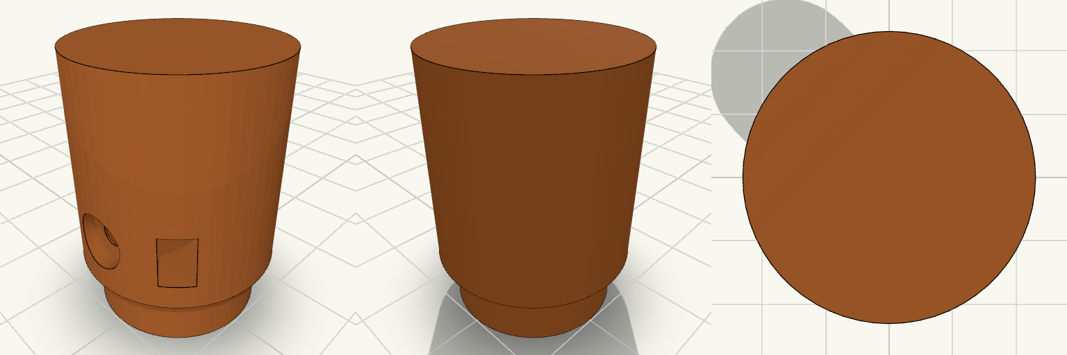
A knurl-free drive wheel for a pinch-feed wire feeder, built like a small industrial pulley: a 24 mm roller with a hub on one side and a blind D-bore that slips over a 5 mm D-shaft. The model is just the roller, standing on its hub and ready to slice. Design notes Blind D-bore, open on the hub face and closed by a wall on the far end, so the closed end shows which side stays out. M3 grub screw hole with a trapped hex nut that slides in through a slot open to the rim. Counterbored screw recess 2 mm deep, so a headed M3 screw sits below the surface and a nylon or TPU sleeve goes on smooth. Hub spaces the roller off the motor face so the two do not rub. Printing Stands on the hub with the bore opening onto the bed, so there is no bridging inside the bore and no supports are needed. Printing upright keeps the roller round. Suggested: PETG, ASA or nylon, 3 or more walls, 25–30% infill.
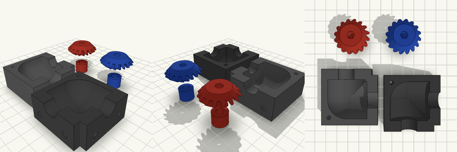
90° Bevel Gearbox Assembly
A fully functional 90-degree bevel gearbox with 5 mm hex bores on both the input and output gears. The split housing prints without supports and clamps the gear stack together when the face flanges are bolted down. Specifications Transmission: 1:1 ratio bevel gears (16 teeth, 90-degree mesh). Input/Output: 5 mm hex bores on both gears, measuring 5.2 mm across the flats including 0.2 mm printing clearance. Housing: Split base and top, each 45 × 45 × 20 mm, designed to print flat without supports. Mounting Interfaces: Four 4.3 mm clearance holes on each face flange, arranged in a 25 mm square pattern. Assembly: The housing halves are clamped together when bolted to a surface using the face flanges; an extra M3 hole in the rear corner provides optional tightening. Printing: All pieces print flat without supports; the housing and gears assemble after printing.
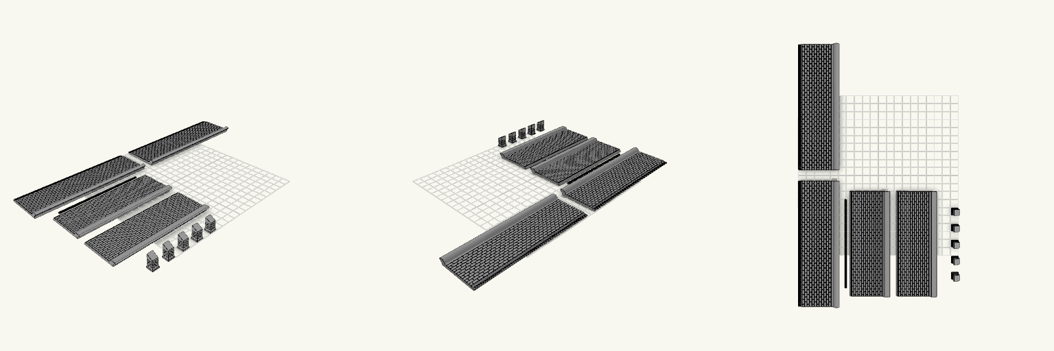
Oo scale buildings half relief roof with ridge tiles
Two tiled OO-scale roof slopes, two slated roof slopes, five brick chimneys and a downpipe, all laid out to fit a 256 × 256 mm bed in one plate. Remix hooks Layout: the four roofs sit side by side along X, with chimneys and the downpipe in the strip on the right. The whole set spans about 240 × 156 mm. Tiled roofs: 46 × 156 mm slab, 3 mm thick, 4.5 mm radius ridge tile wrapping 135°, half-round gutter with 2 mm opening and 0.8 mm walls, closed ends and a 2 mm outflow hole. Slated roofs: 46 × 130 mm, 30° pitch, 2.5 mm courses, 7 mm slates, no gutter. Chimneys: 7 × 7 mm, 16 mm tall, base cut at 30°, printed upside down. Change the height or the cut angle for other roofs. Downpipe: 2 mm × 110 mm solid rod. Lengthen it or add brackets. Pairs well with a printed wall or building shell that matches the 30° and 45° pitches.