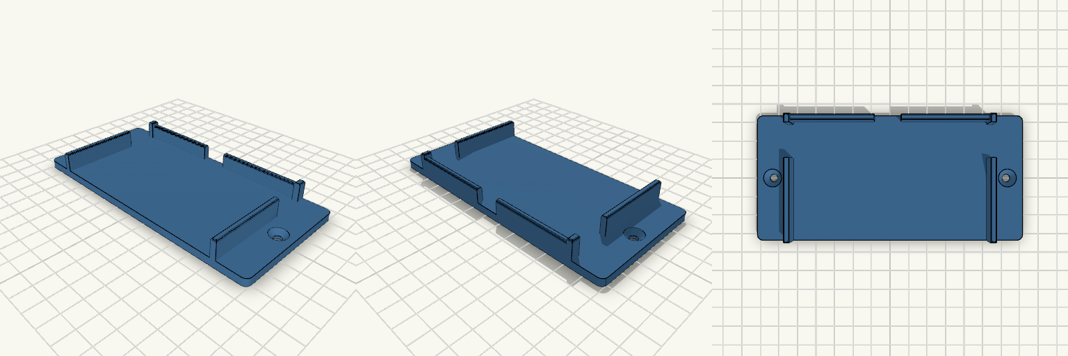
SG90 舵机底板与固定耳片
Made by TweedOcelot
Created 3 days ago
Description
What it's for
30×40 mm 底板,前端带两片独立固定耳片,用于锁 SG90 舵机自带的安装耳。
Dimensions
- 底板 30×40×2 mm,圆角 R1,2 个 φ2 孔,孔距 22 mm
- 耳片各宽 4.2 mm、厚 2 mm、高 14.5 mm
- 耳孔 φ2,中心距 28 mm,孔内侧距耳片内边 0.2 mm
Remix ideas
- 加宽耳片内侧以增加强度
- 恢复 U 型侧壁
Images
More like this
Explore more in Automotive, RC & Hobby →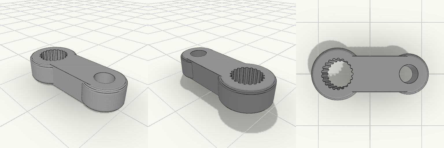
SG90 Spline Single-Arm Servo Horn
A single-arm servo horn for the SG90 micro servo, with a 3.2 mm linkage hole 12 mm from the output shaft centre. Fitment Fits: SG90 and compatible 9 g servos with the 21-tooth, ~4.8 mm output spline. Does not fit: MG90S metal-gear servos with a different spline count, or 25T servos such as MG995/MG996. Arm: 12 mm centre distance, 4 mm thick, rounded edges. Check before printing Test the spline bore on a scrap print. Bore size is ~4.9 mm with small tooth notches, and printer tolerance varies. Adjust it if the fit is loose or tight. The part prints flat with no supports, and PLA works.
ServoLink — SG90 Straight Crank Arm
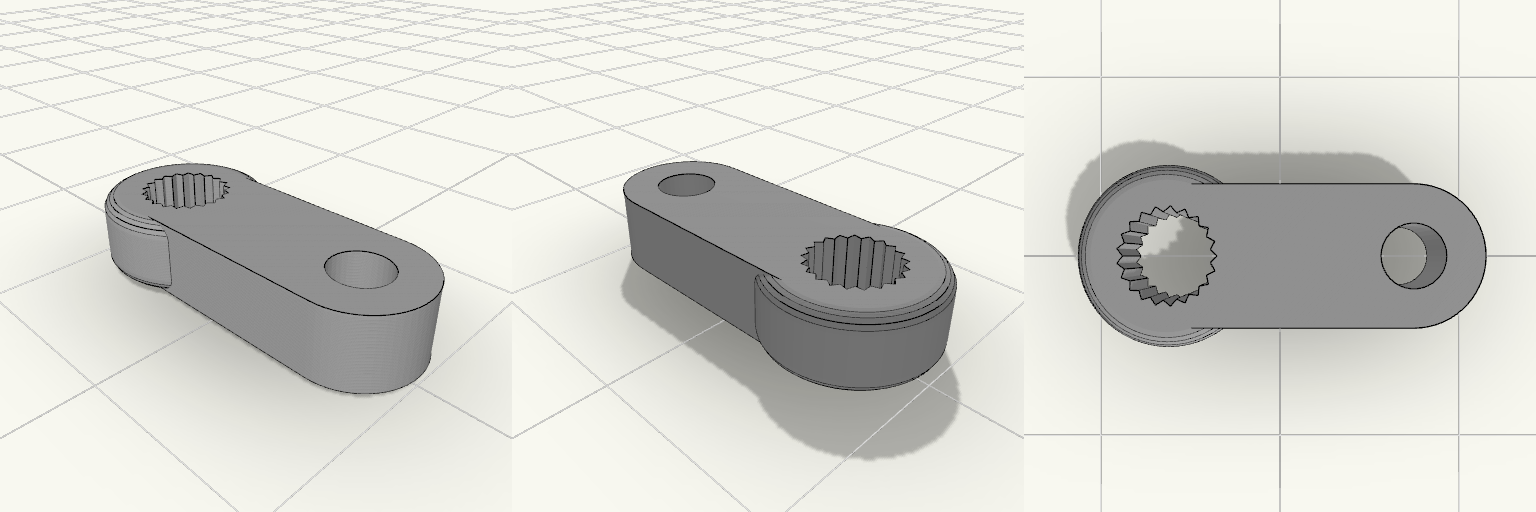
ServoLink is a compact single-bar crank arm for SG90 micro servos. One end carries a 21-tooth spline socket that grips the servo output shaft. The other end has a 3.2 mm round hole for a linkage pin or screw. The part is flat and printable without supports. Dimensions Hole centre to centre: 12 mm Thickness: 4 mm Left hole: SG90 spline, about 4.9 mm across the teeth Right hole: 3.2 mm diameter Hub: 9 mm round, arm end: 7 mm round, with softened edges Print notes PLA, printed flat, no supports The spline is sized close to nominal. Scale the hole slightly if your printer runs tight or loose.
ct1 blinker brackets
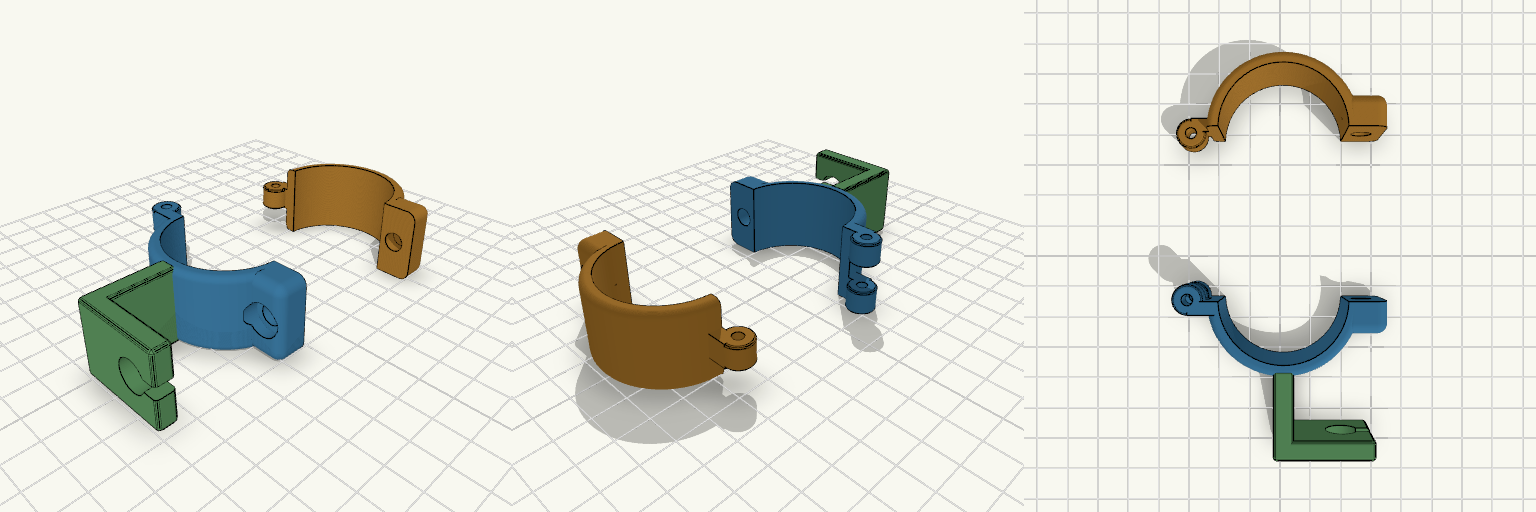
A two-piece hinged clamp for a 38.5 mm motorcycle fork tube, with an L-shaped bracket that carries a 10 mm hole and a 4 mm wire slit for a turn signal post. The halves swing open on an M3 hinge pin and close with one M6 bolt and a hex nut pocket, so the fork stays on the bike. The hinge sits outside the ring on small webs, so the knuckles clear the opposite half when it swings. Bore: 38.0 mm Height: 24 mm, wall 3.5 mm Hinge pin: M3 × 30 bolt or 3 mm rod Clamp bolt: M6 with nut Print the front half with its L bracket, and the rear half separately
Gancho de Garrafa com Braçadeira Snap
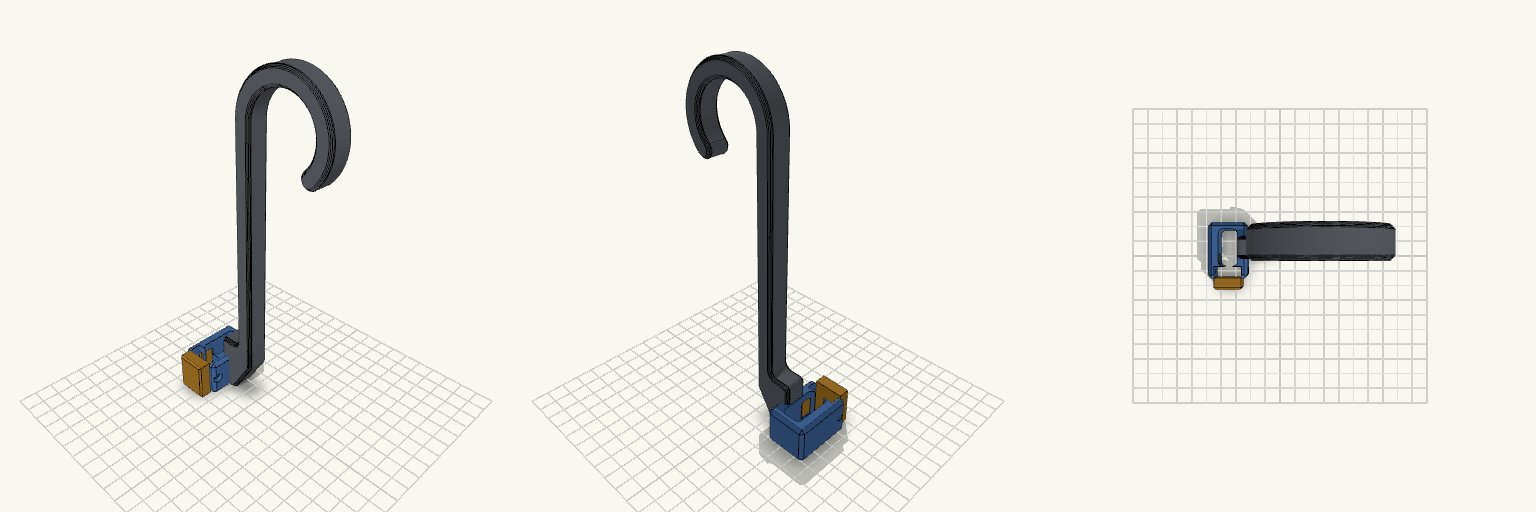
Gancho de garrafa de treino em J, 200 mm, com braçadeira bipartida na base: corpo fixo ligado à haste e tampa separada que fecha por encaixe de pressão ao redor da alça de 12 × 24 mm. Pontos de remix Snap-fit: ganchos flexíveis de 8 mm de comprimento, 1,8 mm de espessura e ressalto de 0,6 mm (armlen, armt, ridge). Entrada em rampa, retenção reta. Folga: 0,2 mm entre tampa e corpo (gap). Trava extra: furo M3 em gota atravessando tampa e corpo, com porca sextavada embutida no lado +X. Paredes: wallx (6,4 mm) e wallf (7,5 mm) definem o tamanho externo; reduza se o furo M3 for dispensado. Haste e gancho: inalterados, seção 10 × 14 mm, bojo de 40 mm, boca de 34 mm. Combina com: parafuso M3 e porca M3 (opcionais); imprima corpo e tampa separados em PETG ou PLA.
Triple Socket Adapter Floor Cradle
What it's for A one-piece floor cradle that holds a triple 12V socket adapter horizontally under a dashboard. The front and top stay open, so the sockets and power switches remain reachable, and side windows keep the side USB ports clear. Dimensions Adapter: 100.4 x 60.85 x 31.72 mm, about 1 mm clearance Side walls: 3 mm thick, 14 mm tall Side windows: 18 mm long, centred 51.38 mm from the front (plus 1 mm clearance) Back lip: 12 mm tall with reinforced corners Mounting ears: 16 mm each end, countersunk screw holes Remix ideas Change the window length to fit a different USB port. Add a third screw hole at the back. Lengthen the ears for wider mounting.
Lumiere araignee
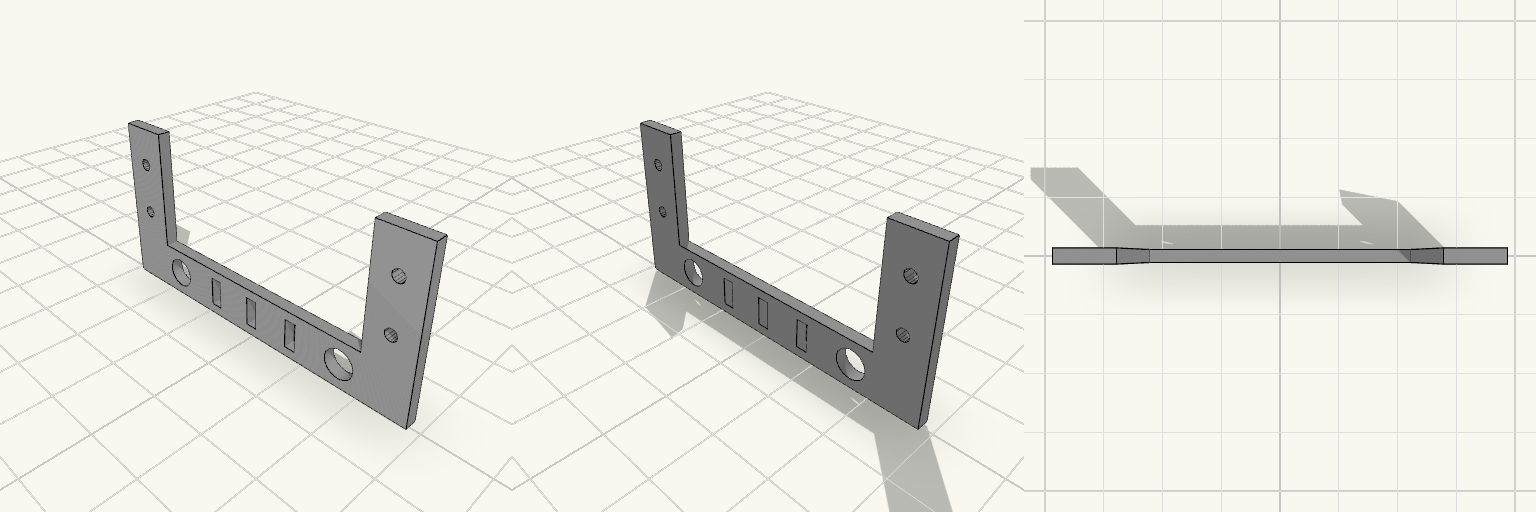
Support en U pour une lumière de téléguidage montée sur servo. La base est debout sous les deux pattes et les porte sur toute leur largeur ; les pattes repartent vers le haut depuis le dessus de la base. Chaque patte est tournée de 90° autour de son axe vertical : 8 mm en X et 2 mm d’épaisseur en Y. La base reçoit deux trous de 5 mm à environ ±17 mm de l’axe, et chaque patte deux trous de 2 mm à 5 mm et 13,5 mm de son bas. Entre les deux trous de 5 mm, la base est ajourée d’une grille de trois fentes de 2 mm de large sur 5 mm de haut, une centrale et deux à ±8 mm, traversant l’épaisseur en Y. L’espace intérieur entre les pattes est réduit de 7,4 mm, ce qui ramène la base à 56,8 mm de long. Caractéristiques Encombrement hors tout : 56,8 × 2 × 27,6 mm (X × Y × hauteur). Base : 56,8 mm en X, 8 mm de haut, 2 mm d’épaisseur en Y ; debout sous les pattes. Pattes : 19,6 mm de haut, 8 mm en X, 2 mm en Y, aux deux extrémités en X, à partir du dessus de la base. Espace entre pattes : réduit de 7,4 mm ; les pattes restent aux extrémités de la base. Perçages des pattes : deux trous de 2 mm par patte, traversant l’épaisseur en Y, à 5 mm et 13,5 mm du bas des pattes. Perçages de base : deux trous de 5 mm à ±17 mm de l’axe, traversant l’épaisseur en Y. Grille de base : trois fentes de 2 mm de large sur 5 mm de haut entre les trous de 5 mm, à −8, 0 et +8 mm, traversant l’épaisseur en Y. Jeu : prévoir quelques dixièmes de jeu dans les trous de 5 mm si les vis doivent rester libres.