AquaDart — Garden Hose Nozzle
Created 3 months ago
Description
AquaDart introduces a streamlined approach to targeted water pressure. This single-piece nozzle adapts a standard garden hose down to a precise 0.2-inch exit stream. The internal geometry is specifically contoured to accelerate water smoothly, while the exterior features deep grooves for secure hand-tightening even when wet.
Dimensions
- Overall height: 63 mm
- Base diameter: 38 mm (at the grip)
- Exit bore: 5.08 mm (0.2 inches)
- Interface: Standard 3/4" Female Garden Hose Thread (11.5 TPI)
Compatibility & Usage
- Designed to thread directly onto standard North American garden hoses and spigots.
- Requires a standard rubber hose washer to sit on the internal ledge. Without the rubber washer, standard garden hose threads will leak under pressure.
Print Notes
- Prints completely completely upright and support-free as oriented.
- Thick walls (4+ perimeters) and 100% infill are heavily recommended to contain the water pressure and prevent layer separation.
- PETG or ABS is preferred if this will be left outdoors in the sun.
Images
More like this
Explore more in Home & Fixtures →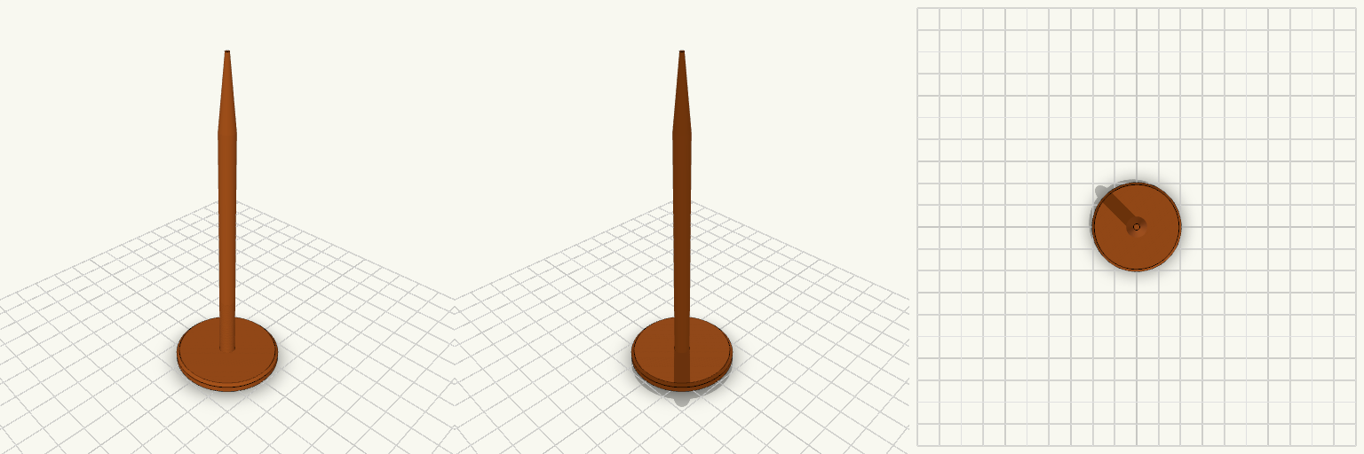
Charging Station Marker Nail
A ground marker nail for holding the position of a robot mower charging station while the charger is stored for the season. It is pushed into the soil where the charger's screw sits in summer. The nail has a wide, flat 40 mm head that stays visible at ground level, a slim 6 mm round shaft, and a tapered point for easy insertion. It prints head-down, so no supports are needed. Head: 40 mm diameter, 4 mm thick, chamfered edge Shaft: 6 mm diameter, about 90 mm long Tip: tapers to a point over 25 mm Overall length: about 119 mm Prints without supports
Beam Clamp Clothes Hanger with Side Hook
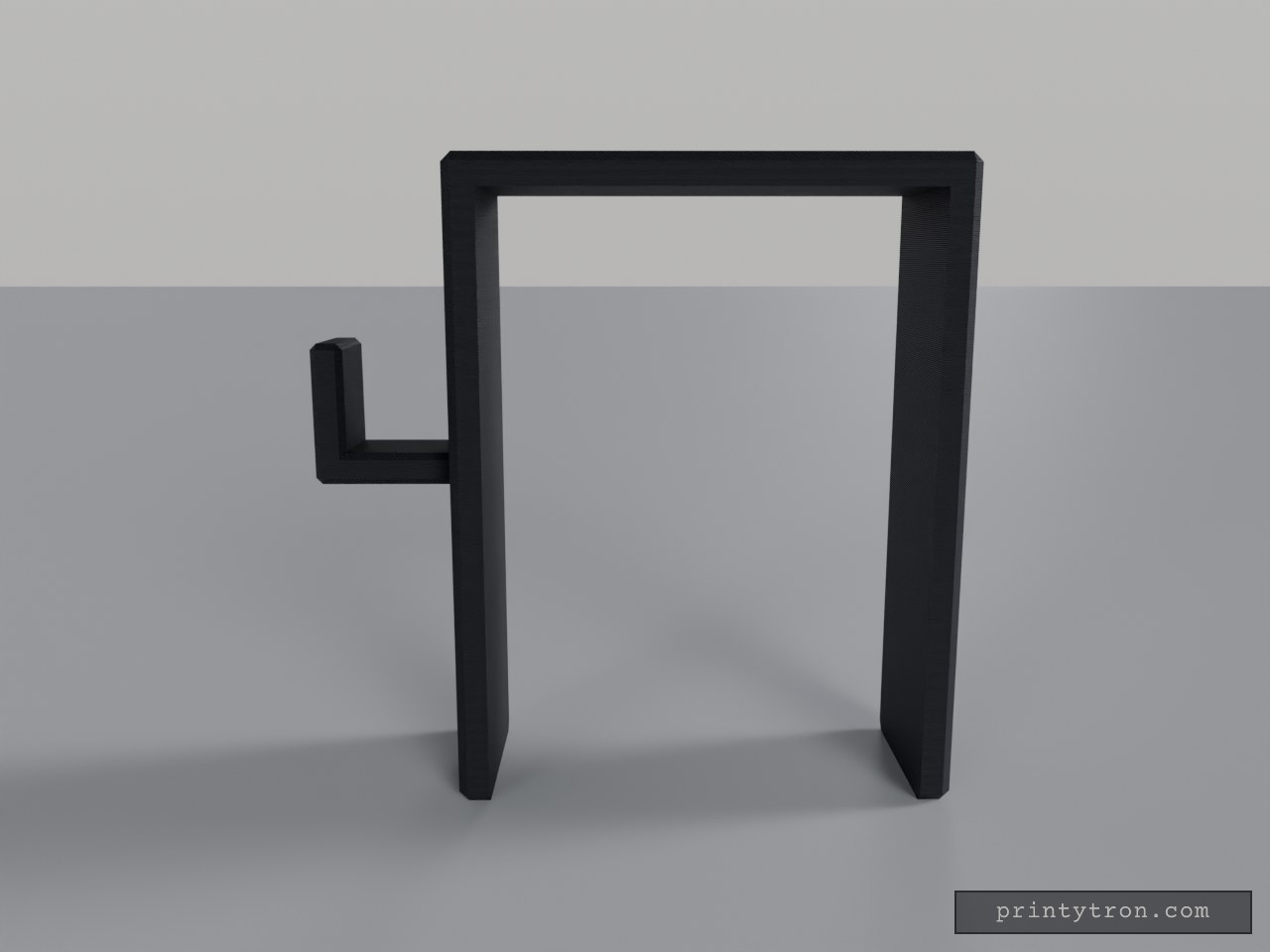
What it's for A saddle that drops over the top of a support beam and turns it into a place to hang clothes. The inverted U-shaped channel grips the beam from above, and a hook projects from one side with an upturned tip so hangers and garments stay put. Beam Saddle — the U-shaped body that slides down over the beam Hook — the side arm with an upward tip for hangers or coats, set at mid-height of the saddle Both areas print as a single piece; nothing needs assembling. Dimensions Saddle opening: 68 mm inner width, sized for a beam of that width Overall saddle: 78 × 30 mm footprint, 100 mm tall Channel: 95 mm deep, with 5 mm thick walls Hook: 22 × 15 × 22 mm, mounted at mid-height so its tip stays inside the 100 mm envelope The 95 mm channel is generous for a shallow beam — the saddle simply sits lower on it, and the hook rides down with it. Print notes Print the saddle opening facing up so the channel needs no supports A few extra perimeters on the hook help when it carries heavy coats Scale the opening slightly if your beam measures over 68 mm Remix ideas Lengthen the hook for bulky winter coats Shorten the legs for a shallower beam and keep the height with a taller top plate Add a second hook on the opposite side for more hanging room Add a small lip or screw hole at the bottom of the saddle to stop it shifting sideways
Industrial Saddle Wall-Mount Air-Hose Clip
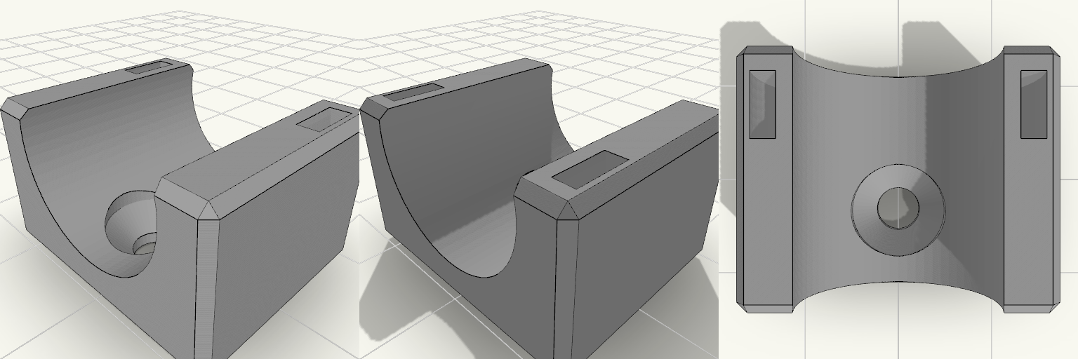
A plain block with a channel across its top and a single hole sunk into the floor of that channel — drive a drywall screw through it, drop the 5/8″ OD air hose in, and the fixing disappears beneath the hose. A slot cuts through the other half of the block, so a zip tie loops down over the hose and cinches it without ever crossing the screw. No side tabs, no bracket ears, nothing protruding past the saddle: a small, purely functional piece of wall hardware with a squared-off, industrial silhouette. Design notes Top channel sized for 5/8″ OD air hose, with a little clearance. Countersunk screw hole sits in the channel floor with a 9 mm countersink, wide enough for a typical drywall screw head and hidden once the hose is seated. Zip tie slot is offset to the far half of the block, clear of the screw area; takes a common tie up to about 5 mm wide. Load order matters: drive the screw first, then lay the hose in and tension the tie. With a single fastener the block can spin before the hose is loaded — snug the screw down before fitting the hose so it stays square to the wall. Block is 20 mm long, 24.3 × 20 × 14.1 mm overall as it sits on the build plate. Prints as a single body; screws and zip ties are separate hardware.
U-Turn — Zweiteilige 180°-Schlauchführung
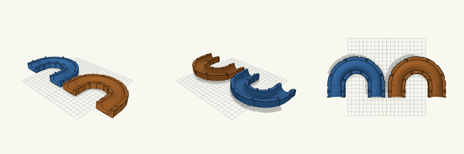
U-Turn ist eine zweiteilige 180°-Schlauchführung, die einen Schlauch mit 25 mm Außendurchmesser in einem gleichmäßigen Bogen umlenkt, sodass Ein- und Auslauf parallel nebeneinander in dieselbe Richtung zeigen. Statt Schrauben oder Muttern halten handelsübliche Kabelbinder die beiden Hälften zusammen: Mehrere außenliegende Nuten laufen um den gesamten Querschnitt, sodass die Binder nicht seitlich abrutschen und nicht in den Schlauchkanal hineinragen. Die flache Außenseite liegt beim Druck unten, die Nut zeigt nach oben — dadurch kommen beide Hälften ohne Stützmaterial aus. Maße Schlauchkanal: 26 mm Innendurchmesser für einen Schlauch mit 25 mm Außendurchmesser Bogen: exakt 180°, Biegeradius 50 mm zur Mittellinie, Mittellinien 100 mm auseinander Gerade Ein- und Auslaufstrecken: je 30 mm, an den Enden auf etwa 33 mm aufgeweitet Wandstärke: 4 mm; Querschnitt 42 mm breit, jede Hälfte 17 mm hoch Kabelbindernuten: 5,2 mm breit und 1,5 mm tief für 4,8 mm breite Binder; Restwand an der dünnsten Stelle 2,5 mm Aufbau Beide Hälften verlaufen über den gesamten 180°-Bogen und tragen je eine halbrunde Nut, die zusammengesetzt einen geschlossenen, kreisförmigen Kanal ergibt. Die Hälfte mit den Zapfen trägt Zapfen von 5 mm Durchmesser und 4 mm Höhe, die Gegenhälfte passende Aussparungen von 5,4 mm Durchmesser — das ergibt ein Montagespiel von 0,2 mm je Seite. Die Zapfen sitzen beidseitig des Kanals, sowohl auf dem Bogen als auch an den geraden Endstücken, und verhindern ein seitliches Verrutschen. Montage Die Hälfte mit den Aussparungen umdrehen, auf die Hälfte mit den Zapfen setzen und andrücken. Anschließend Kabelbinder durch die Nuten führen und festziehen: fünf Nuten verteilen sich gleichmäßig entlang des U-Bogens, je zwei sitzen an den geraden Endstücken. Druckhinweise Beide Hälften werden getrennt gedruckt und anschließend zusammengesteckt; die Kabelbinder übernehmen die Fixierung. Der Kanal ist an beiden Enden großzügig abgerundet, damit der Schlauch ohne Knickstellen ein- und ausläuft.
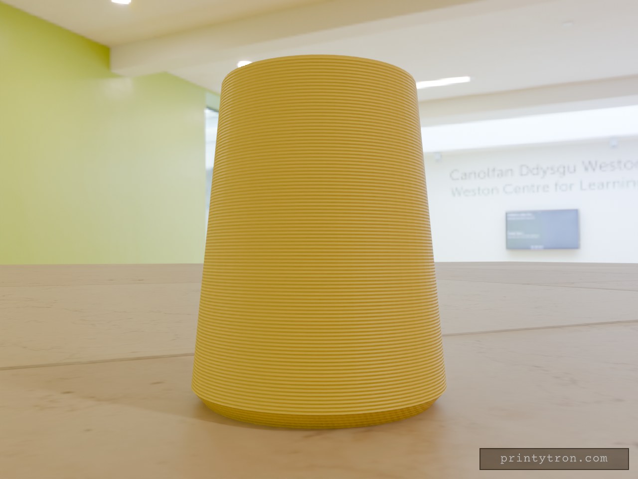
Cabinet Handl Bumper
A cabinet handle end that slams into the door or wall now has a cone-shaped TPU bumper to take the hit. The bumper slides over the handle end and stays put on an 11.8 mm blind hole. Key numbers Height: 32 mm Base diameter: 26 mm, with a 1.5 mm 45° chamfer on the bottom edge Narrow end diameter: 20 mm Hole: 11.8 mm diameter, 24 mm deep, opening at the narrow end Print: TPU, base down, no supports needed
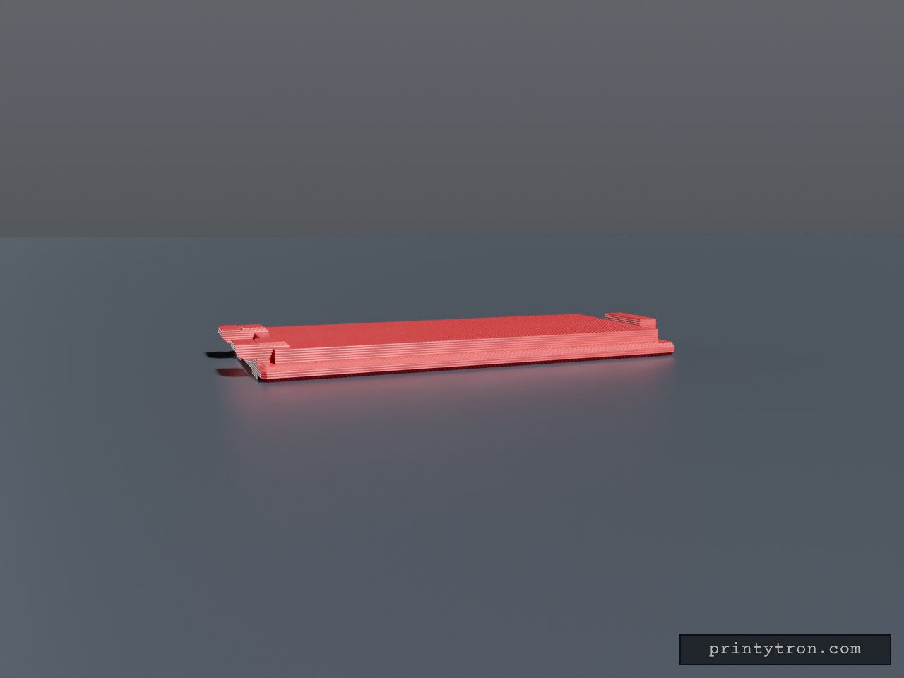
Bug Zapper Battery Cover 27.65 x 60 mm
Sliding battery compartment cover plate for a bug zapper, 27.65 x 60 mm. A locating lip sits in the compartment opening, a latch tab sits at one end, and two low retention tabs at the opposite end keep the cover from falling out. Plate: 27.65 x 60 x 2 mm, chamfered edges Lip: 23.65 x 56 mm, 3.8 mm total height Retention tabs: two, 5 mm wide, flush with lip height, at X = ±8 mm Latch tab: 10 mm wide at the +Y end Grip grooves on the outer face Dimensions are estimates; verify against the original opening