Charging Station Marker Nail
Created 3 days ago
Description
A ground marker nail for holding the position of a robot mower charging station while the charger is stored for the season. It is pushed into the soil where the charger's screw sits in summer.
The nail has a wide, flat 40 mm head that stays visible at ground level, a slim 6 mm round shaft, and a tapered point for easy insertion. It prints head-down, so no supports are needed.
- Head: 40 mm diameter, 4 mm thick, chamfered edge
- Shaft: 6 mm diameter, about 90 mm long
- Tip: tapers to a point over 25 mm
- Overall length: about 119 mm
- Prints without supports
Images
More like this
Explore more in Home & Fixtures →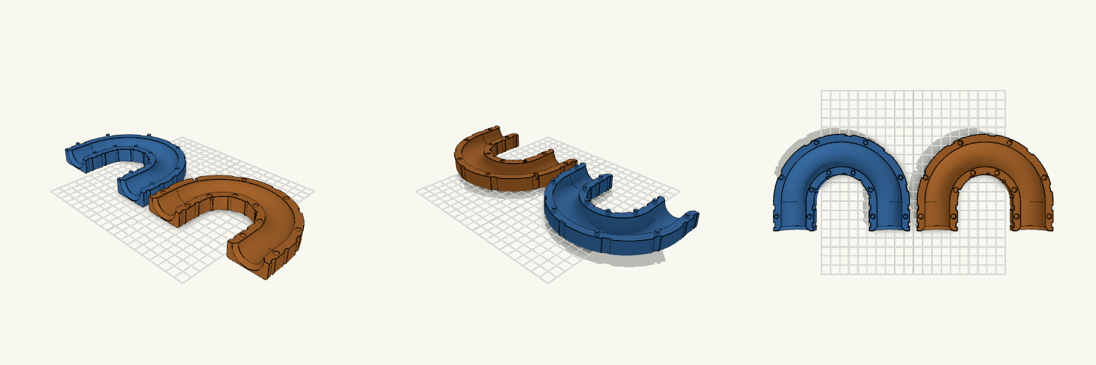
U-Turn — Zweiteilige 180°-Schlauchführung
U-Turn ist eine zweiteilige 180°-Schlauchführung, die einen Schlauch mit 25 mm Außendurchmesser in einem gleichmäßigen Bogen umlenkt, sodass Ein- und Auslauf parallel nebeneinander in dieselbe Richtung zeigen. Statt Schrauben oder Muttern halten handelsübliche Kabelbinder die beiden Hälften zusammen: Mehrere außenliegende Nuten laufen um den gesamten Querschnitt, sodass die Binder nicht seitlich abrutschen und nicht in den Schlauchkanal hineinragen. Die flache Außenseite liegt beim Druck unten, die Nut zeigt nach oben — dadurch kommen beide Hälften ohne Stützmaterial aus. Maße Schlauchkanal: 26 mm Innendurchmesser für einen Schlauch mit 25 mm Außendurchmesser Bogen: exakt 180°, Biegeradius 50 mm zur Mittellinie, Mittellinien 100 mm auseinander Gerade Ein- und Auslaufstrecken: je 30 mm, an den Enden auf etwa 33 mm aufgeweitet Wandstärke: 4 mm; Querschnitt 42 mm breit, jede Hälfte 17 mm hoch Kabelbindernuten: 5,2 mm breit und 1,5 mm tief für 4,8 mm breite Binder; Restwand an der dünnsten Stelle 2,5 mm Aufbau Beide Hälften verlaufen über den gesamten 180°-Bogen und tragen je eine halbrunde Nut, die zusammengesetzt einen geschlossenen, kreisförmigen Kanal ergibt. Die Hälfte mit den Zapfen trägt Zapfen von 5 mm Durchmesser und 4 mm Höhe, die Gegenhälfte passende Aussparungen von 5,4 mm Durchmesser — das ergibt ein Montagespiel von 0,2 mm je Seite. Die Zapfen sitzen beidseitig des Kanals, sowohl auf dem Bogen als auch an den geraden Endstücken, und verhindern ein seitliches Verrutschen. Montage Die Hälfte mit den Aussparungen umdrehen, auf die Hälfte mit den Zapfen setzen und andrücken. Anschließend Kabelbinder durch die Nuten führen und festziehen: fünf Nuten verteilen sich gleichmäßig entlang des U-Bogens, je zwei sitzen an den geraden Endstücken. Druckhinweise Beide Hälften werden getrennt gedruckt und anschließend zusammengesteckt; die Kabelbinder übernehmen die Fixierung. Der Kanal ist an beiden Enden großzügig abgerundet, damit der Schlauch ohne Knickstellen ein- und ausläuft.
Cabinet Handl Bumper
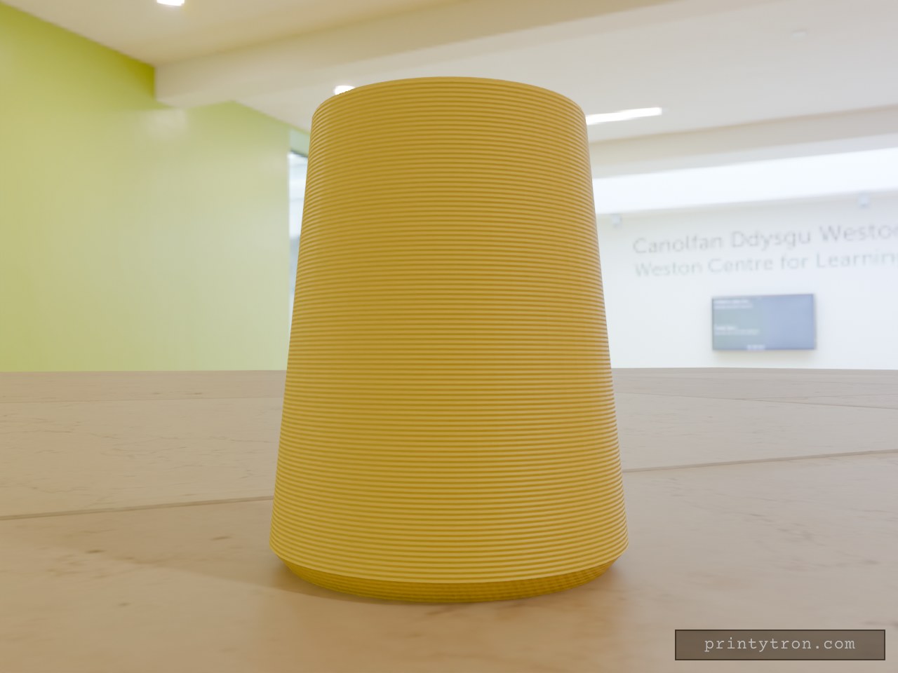
A cabinet handle end that slams into the door or wall now has a cone-shaped TPU bumper to take the hit. The bumper slides over the handle end and stays put on an 11.8 mm blind hole. Key numbers Height: 32 mm Base diameter: 26 mm, with a 1.5 mm 45° chamfer on the bottom edge Narrow end diameter: 20 mm Hole: 11.8 mm diameter, 24 mm deep, opening at the narrow end Print: TPU, base down, no supports needed
Bug Zapper Battery Cover 27.65 x 60 mm
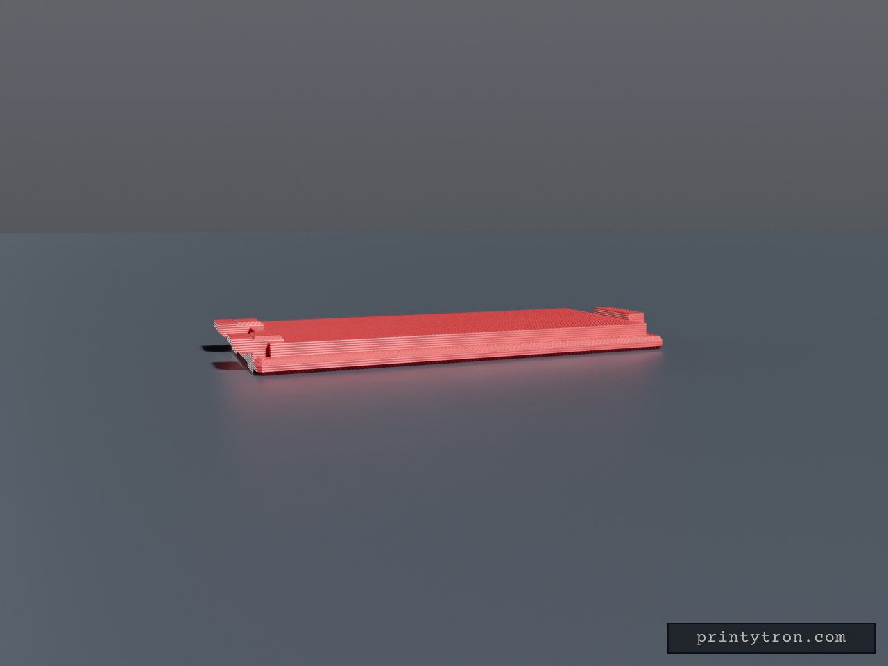
Sliding battery compartment cover plate for a bug zapper, 27.65 x 60 mm. A locating lip sits in the compartment opening, a latch tab sits at one end, and two low retention tabs at the opposite end keep the cover from falling out. Plate: 27.65 x 60 x 2 mm, chamfered edges Lip: 23.65 x 56 mm, 3.8 mm total height Retention tabs: two, 5 mm wide, flush with lip height, at X = ±8 mm Latch tab: 10 mm wide at the +Y end Grip grooves on the outer face Dimensions are estimates; verify against the original opening
Antenna Cover With Mounting Flange
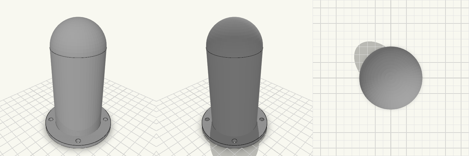
An antenna protective cover that keeps weather and knocks off the antenna: a hollow cylinder with a domed top, open at the bottom, on a flat bolt-down flange. Total height: 115 mm including the 4 mm flange Body: 50 mm outer, 46 mm inner diameter (2 mm wall), dome radius 25 mm blending tangentially into the cylinder Flange: 72 mm diameter, 4 mm thick Holes: four 5 mm through-holes in a square, 43.1 mm between adjacent centres Print: open end down on the flange, no supports needed, 3+ perimeters recommended
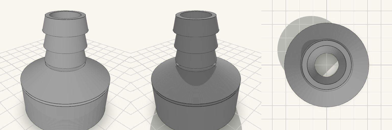
Garden-Plumbing Workhorse: BSP to 3/4 Hose Barb
A straight-line adapter that bridges a 1-1/4" BSP female threaded socket to a 3/4" hose barb, with a tapered shoulder carrying the eye from the wide threaded end down to the narrow ridged nozzle. It reads like a piece of honest utility hardware: a ring of 11 TPI thread at one end, three crisp ridges at the other, and a 15 mm bore running clean through a compact 55 mm body — short enough to tuck into tight pump and tap arrangements without a loop of hose fighting for room. The barb's ridges ramp up gently from the tip and widen toward the body, then drop off in a sharp step — the hose slides on without a fight, and the step keeps it from backing off again. Design notes: 1-1/4" BSP female socket, 11 TPI, 41.91 mm major diameter, 18 mm deep Tapered transition from the socket down to the barb 19 mm barb with three retention ridges, 7 mm tall and spaced 8 mm apart, narrow at the tip and widening to a step at the body side, for 3/4" hose 15 mm bore through the full length; 55 mm overall Prints as a single piece, sitting upright at roughly 50 × 50 mm on the plate Fit and sealing: The thread is modelled at nominal size with no added clearance, so a first test fit against the male fitting is worth doing — if it binds, opening it out by 0.2–0.4 mm is the easy fix. For a watertight joint, wrap the thread with PTFE tape or seat a flat washer against the socket floor. The shortened barb leaves less hose length to grip; a hose clip just behind the final ridge makes up for it. Pairs naturally with garden hose, pump outlets and tank fittings.
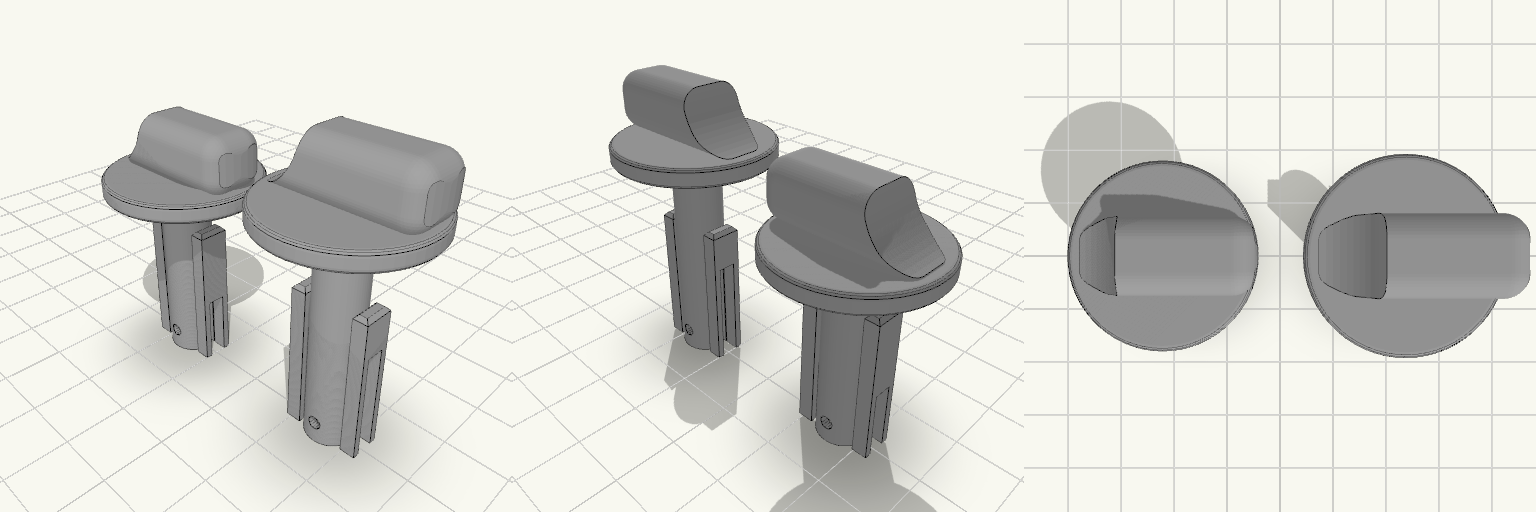
Perilla de estufa de repuesto con vástago reforzado
La perilla de la estufa que gira en falso o se parte deja el fuego sin control; esta perilla de repuesto se calza sobre el caño de gas y se traba con pasador, con el pulgar recortado al contorno del collar y todos los bordes del agarre redondeados para girar sin engancharse. La placa trae dos perillas: la original y una copia con vástago de 35 mm para cambiar el largo según la estufa. Cotas que deciden el calce Dos perillas en la misma placa: la original mide 41,5 mm de alto total (12 mm de cabeza + 29,5 mm de vástago); la copia mide 47 mm de alto total (12 mm de cabeza + 35 mm de vástago). En la placa ocupan 58 × 26 × 47 mm. Vástago: 8 mm de diámetro exterior, con dos aletas planas de refuerzo de 24 mm a los lados; en la copia, las aletas quedan en la zona de la punta. Vástago hueco: orificio de 5,5 mm de diámetro, abierto en la punta. En la original llega a 26 mm de profundidad y queda ciego en los últimos 3,5 mm hacia la cabeza, con paredes de aproximadamente 1,25 mm; la copia mantiene el mismo orificio de 5,5 mm. Agujero pasante: 2,2 mm de diámetro, horizontal, con el centro a 3,5 mm del extremo inferior; cruza la cavidad del vástago, así que la chaveta atraviesa el caño de gas. Endija: 3 mm de ancho, abierta en la punta; va a 90° del agujero del pasador, atraviesa el vástago y corta también las aletas laterales, dejando el extremo dividido en dos mitades flexibles. En la original llega a 11 mm; en la copia llega a 17,5 mm, la mitad de su vástago. Cabeza: collar de 26 mm de diámetro por 3 mm de alto; el pulgar mide 26 mm de ancho, 10 mm de grosor y 9 mm de alto sobre el collar, ya no pasa el contorno del collar, es plano de un lado y baja curvo del otro. Todas las aristas del pulgar tienen 3 mm de radio; los bordes del collar tienen 0,8 mm. Cada perilla se imprime de una sola pieza; la endija no separa el modelo, solo deja flexibles las dos mitades del extremo. El acabado negro mate sale del filamento que elijas, no de la geometría. Antes de imprimir, mide el diámetro del caño de gas y el del pasador: el hueco del vástago y el agujero pasante son las dos cotas que no perdonan, y si no coinciden es mejor ajustarlas antes de gastar material.