Antenna Cover With Mounting Flange
Created today
Description
An antenna protective cover that keeps weather and knocks off the antenna: a hollow cylinder with a domed top, open at the bottom, on a flat bolt-down flange.
- Total height: 115 mm including the 4 mm flange
- Body: 50 mm outer, 46 mm inner diameter (2 mm wall), dome radius 25 mm blending tangentially into the cylinder
- Flange: 72 mm diameter, 4 mm thick
- Holes: four 5 mm through-holes in a square, 43.1 mm between adjacent centres
- Print: open end down on the flange, no supports needed, 3+ perimeters recommended
Images
More like this
Explore more in Home & Fixtures →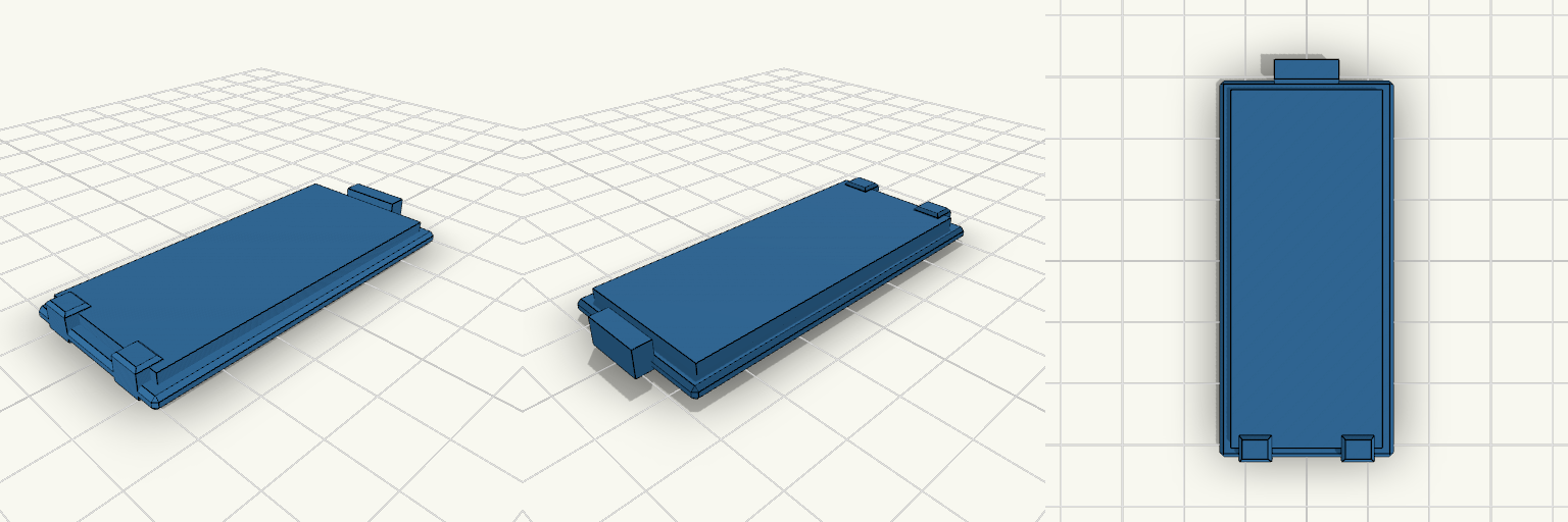
Bug Zapper Battery Cover 27.65 x 60 mm
Sliding battery compartment cover plate for a bug zapper, 27.65 x 60 mm. A locating lip sits in the compartment opening, a latch tab sits at one end, and two low retention tabs at the opposite end keep the cover from falling out. Plate: 27.65 x 60 x 2 mm, chamfered edges Lip: 23.65 x 56 mm, 3.8 mm total height Retention tabs: two, 5 mm wide, flush with lip height, at X = ±8 mm Latch tab: 10 mm wide at the +Y end Grip grooves on the outer face Dimensions are estimates; verify against the original opening
100x59 Oval Body Hole Cover with Snap Clips
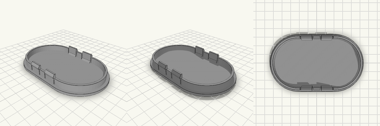
Einsteckbare Abdeckung für eine ovale Öffnung von 100 × 59 mm in etwa 1 mm dickem Blech. Die Frontplatte ist vollständig geschlossen und liegt mit einem 3 mm breiten Auflageflansch rundum auf dem Blech auf; außen misst die Abdeckung 106 × 65 mm bei 2,5 mm Plattendicke. Auf der Rückseite zentriert ein Rahmen mit 2 mm Wandstärke und einer Innenöffnung von 96 × 55 mm als ovales Langloch mit Endradius 27,5 mm. Der Rahmen reicht 7 mm über den Flansch hinaus. Die vier flexiblen Clips – je zwei an den langen Kanten – haben 0,8 mm hohe Haken und angeschrägte Einführflächen; die Rastkante sitzt 7 mm über der Flanschfläche. Mit den verlängerten Federschlitzen baut die Abdeckung insgesamt 13 mm hoch. Bei 1 mm Blech bleibt zwischen Blech und Rastkante in Einsteckrichtung Luft; der Clip rastet erst nach 7 mm Einstecktiefe ein. Werkzeuglose Montage und Demontage Einteiliger Körper, keine Schrauben und kein Kleber Flansch nach unten drucken, in PETG oder ASA Clipsitz beim ersten Druck prüfen, da die Federwirkung des Materials schwankt
100 mm OD Flange, 45 mm Bore
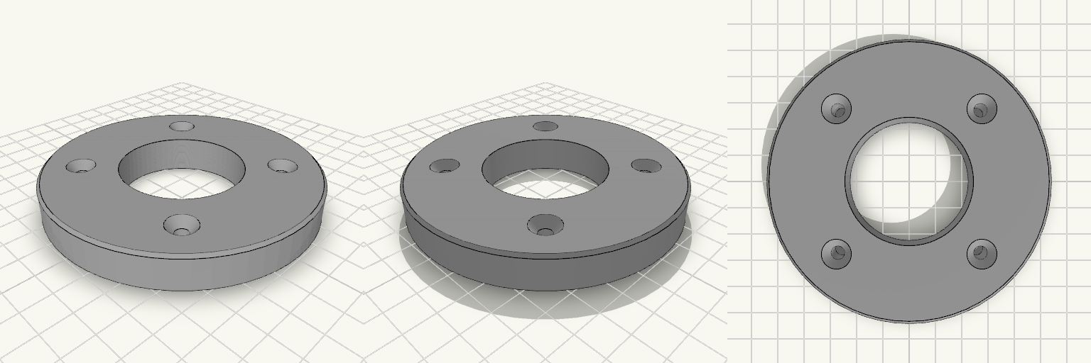
A flat round flange, 100 mm outside diameter and 13 mm thick, with a 45 mm bore straight through the middle. Four 5 mm holes sit on a 72 mm bolt circle at 45°, 135°, 225° and 315°, countersunk from the top face and 10.5 mm across at the rim. The outer edges carry a 1 mm chamfer, so there is no sharp rim to catch on. What it fits Bore: 45 mm nominal — measure the shaft, tube or spigot it goes over with calipers first. A printed 45 mm bore comes out undersized on most machines, so plan on reaming or drilling to size. Bolt pattern: four holes on a 72 mm bolt circle, at the diagonal positions rather than at 12/3/6/9 o'clock. Confirm the orientation of the mating part before drilling anything. Fasteners: 5 mm clearance with a countersink 10.5 mm across, sized around M5 flat-head screws so the heads sit at or just below the top face. Longer screws will not sit flush, and the 13 mm body sets how much thread you have to play with. Face: the 100 mm diameter leaves roughly 27.5 mm of material between the bore edge and the outer edge. What it does not have No hub and no raised face — it is a plain flat disc, so it will not self-centre on a register. No thread, no taper and no keyway in the bore. No O-ring groove or gasket recess; sealing has to come from the mating faces or a separate gasket. No second bolt pattern — if the part you are mating to has six or eight holes, or a circle other than 72 mm, this will not bolt on. Before you print Measure the bolt circle and the hole positions on the part you are mating to, centre-to-centre, and check that the four-hole diagonal layout matches. Also check that 13 mm of thickness clears whatever sits behind the flange, since the countersinks eat into the top face and leave less material under the heads than a plain 13 mm plate would suggest. Prints flat on the bottom face with no supports; the chamfer and the bore both come out clean laid down that way, and the countersinks form on the top surface without bridging.
Finger Trunking with Snap-On Lid
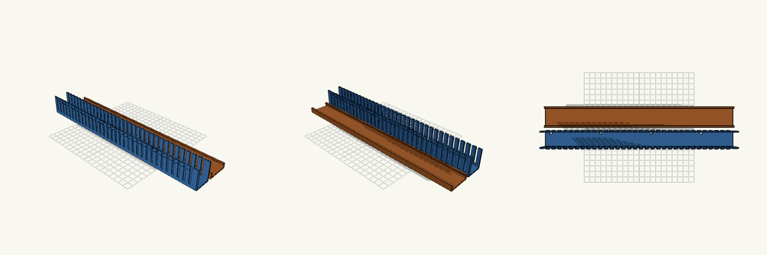
Finger trunking that blocks access to your mounting holes is a problem. This one has floor slots cut where the screws and the access hole need to be, plus a snap-on lid. The walls are free-standing fingers with barbs at the tips. The lid's inward lip clips under the barbs. Size: 340 × 30 × 35 mm, with 2 mm walls and a 2 mm floor. Fingers: 4 mm gaps on a 10 mm pitch. M3 slots: Four slots, 3.4 mm wide and 5.4 mm long. They sit at 10, 100.75, 191.5 and 282.25 mm from the left end, 90.75 mm apart. Access hole: 7 mm diameter, 201.5 mm from the left end. Slot line: All slots sit 10.786 mm toward +Y from the centreline. Printing: The trunking is longer than most print beds. Print it diagonally or split it. The lid lip is a small overhang when printed flat.
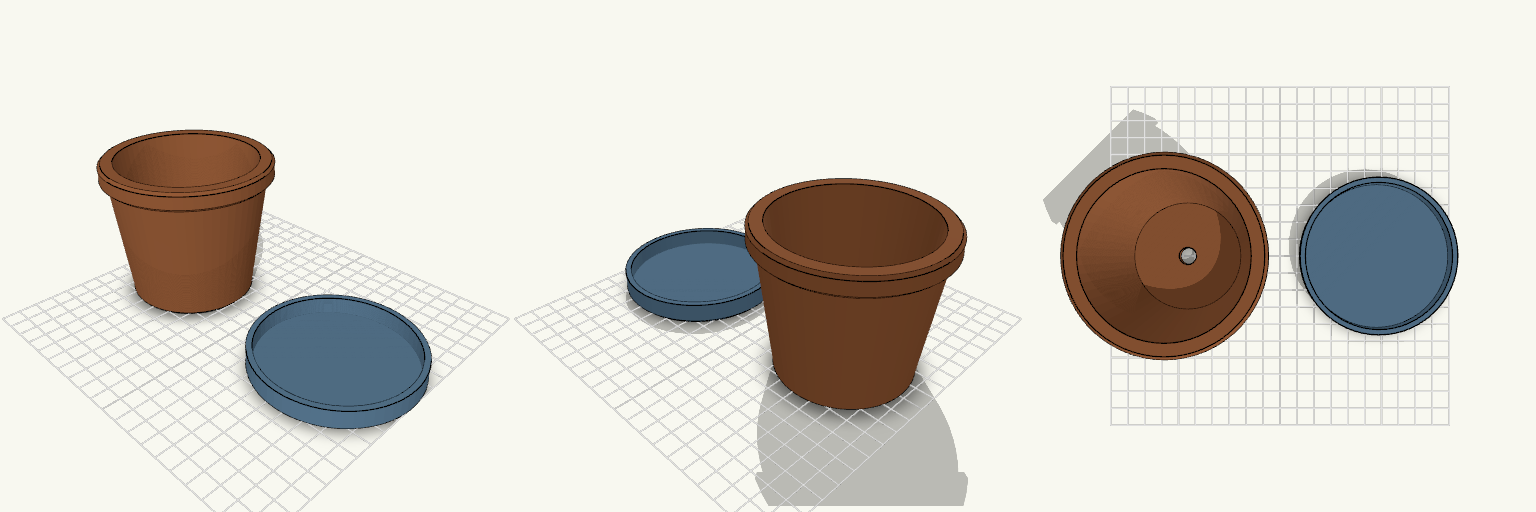
Cactus Pot With Drainage Hole
A cactus pot with a drainage hole, so water leaves the soil instead of rotting the roots. A separate saucer catches the runoff so it doesn't end up on the windowsill. Key numbers Pot: 70 mm base, 90 mm opening, 75 mm tall, 96 mm rim lip Drainage hole: 10 mm diameter, centred in the 6 mm floor Saucer: 90 mm diameter, 12 mm tall, 2.5 mm floor. The pot's 70 mm base sits inside it. Print: no supports needed, both pieces print upright. 0.2 mm layers, PETG or PLA.
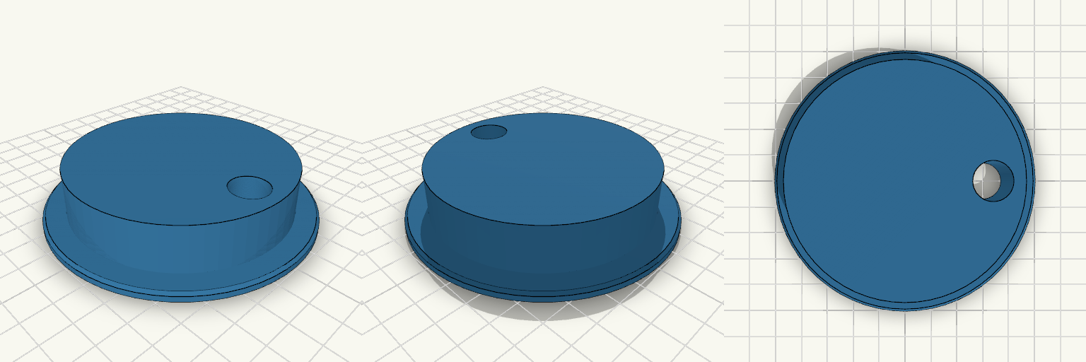
83mm Desk Grommet with Sealed Hollow Body
A one-piece desk grommet for an 83 mm hole, with an off-center cable passage. The barrel drops through the desk and the 99 mm flange rests on the surface; 3 mm caps close the part at both ends and the interior is a sealed hollow, so it uses little filament for its size. A 14 mm cable hole sits 30 mm from the center, about 4 mm in from the rim, and passes through the flange and both caps. It takes most round power cables but will not pass a plug. Desk hole: 83 mm Barrel: 82.6 mm outside diameter, 20 mm tall Flange: 99 mm diameter Cable hole: 14 mm diameter, 30 mm from center, near the edge Wall and cap thickness: 3 mm; cable-hole wall: 2 mm Interior: sealed hollow cavity Fit: desk tops up to about 17 mm thick Print: one piece; no external supports; the enclosed cavity will bridge internally near the top of the void Overall footprint on the plate: 99 × 99 × 20 mm