Clinical Auto-Retracting Tape Mount
Created 1 months ago
Description
A functional, single-piece, print-in-place wrist mount for an oval retractable tape measure, designed specifically for clinical nerve conduction studies.
This iteration adds two key features requested by the clinician:
- Captive Retention: The top lip now has a deep 2.5mm overhang, completely trapping the tape measure so it cannot fall out during active movement. The side scallops were raised to keep the lip rigid and continuous.
- Auto-Retract Cantilever: The floor features an integrated, FDM-compliant C-shaped flexure tongue holding a 4.5mm domed pressure pad. When the tape measure is snapped in, this boss continuously depresses the central retract button, allowing the user to simply pull the tape out and let go for immediate automatic retraction.
Setup and Usage
Snap the 65×59mm tape measure in button-side down. Thread a standard 20mm or 22mm fabric strap through the side loops for a comfortable, non-restrictive fit on the forearm. Prints flat on its base without supports.
Photos
Technical views
More like this
Explore more in Workshop & Tools →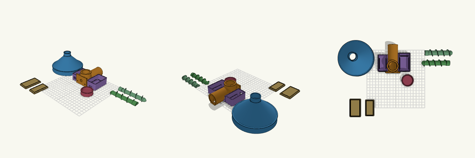
28BYJ-48 Auger Housing with Dual Side Cases
Auger housing for a 28BYJ-48 stepper, with a 30-pin ESP32 DevKit case on one side of the tube and a buck converter case on the other. Each case prints as one piece with the housing and has its own lid. What it fits Motor: 28BYJ-48, 35 mm screw spacing, 10 mm shaft boss hole. ESP32 case (+X side): 30-pin DevKit, 51.5 x 28.5 mm, USB cutout on the front wall. Buck converter case (-X side): about 45 x 21 mm, with a 14 mm motor-lead slot on the front wall. Funnel: female 109 mm inside-diameter thread. The 6 mm pitch is an assumption. Check before printing Measure the ESP32 board width and the buck converter size. The rails leave about 0.4 mm per side. Does not fit 38-pin ESP32 boards, which are wider.
Elliptical Pedal Insert 48x40 Offset Hole
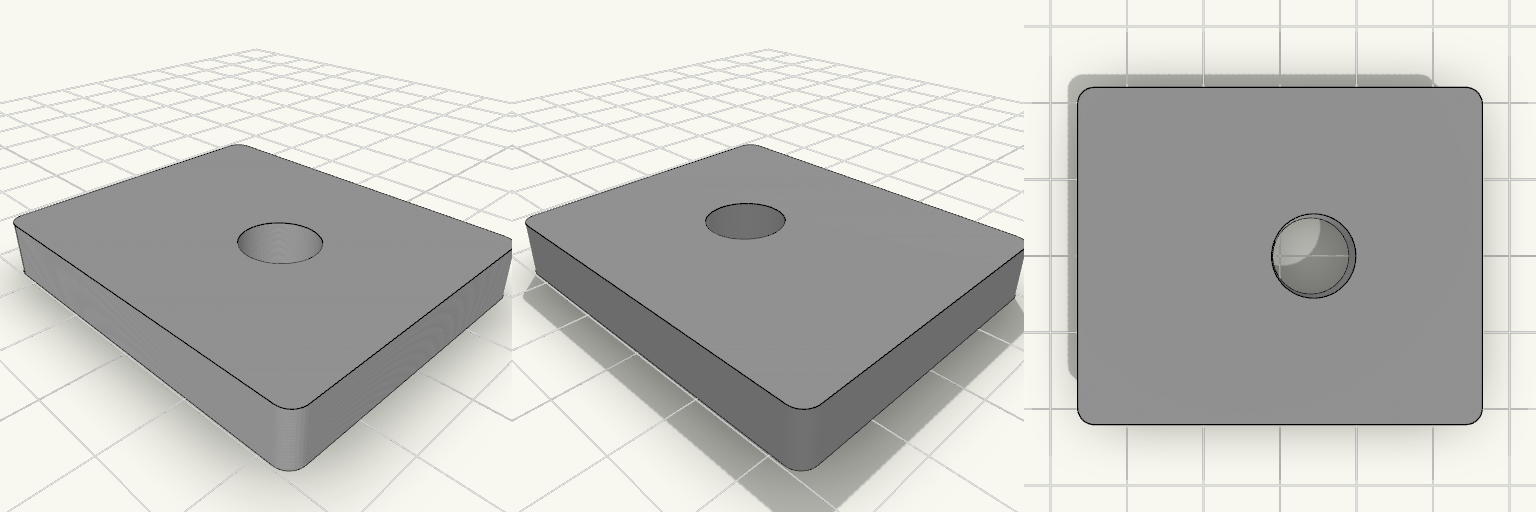
What it's for Central reinforcement insert for an elliptical trainer pedal, bonded into the damaged opening. Flat top, ribbed underside. Dimensions Base: 48 × 40 × 7 mm, rounded corners Through-hole: 10 mm, centered at 24 mm along the length and 4 mm toward the top edge from the width center 18 mm boss around the hole, 5 ribs to a 3 mm frame Remix ideas Change the hole offset for a different pedal Add or remove ribs Thicken the frame for heavier loads
Rough Cone light diffuser
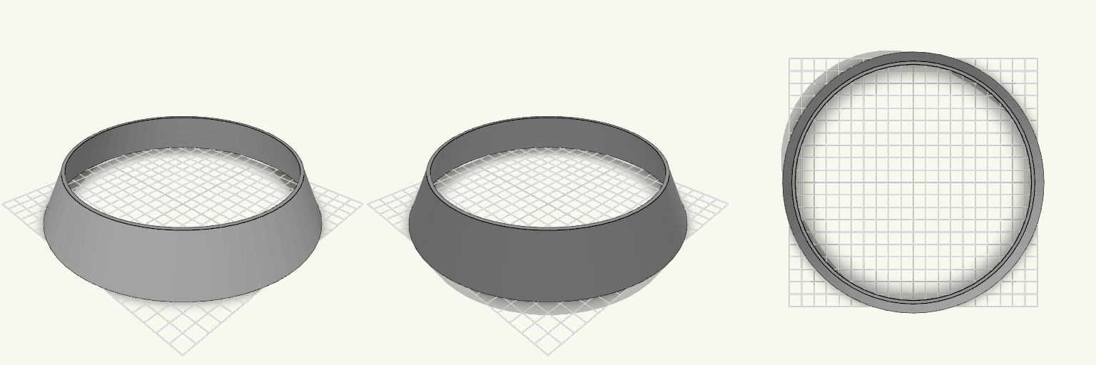
Two round openings that don't share a diameter is the small annoyance that stops everything downstream — the hose won't seat, the liner won't sit, the funnel wobbles instead of funnelling. This is the plain fix: a hollow truncated cone, wide at the bottom and narrow at the top, open at both ends so anything poured or pushed through it passes straight through instead of bottoming out. Fit dimensions Bottom outer diameter: 210 mm Top inner diameter: 170 mm Overall height: 38 mm Wall thickness: 2.4 mm Both ends open — it is a sleeve, not a capped cone Printing It prints as one piece sitting on its 210 mm base, so no assembly and no separate parts to line up afterwards. The wall is thin enough to stay flexible in the hand but still hold its shape, and the shallow flare means the outer surface is not a long unsupported overhang. Check the 170 mm top against whatever has to pass through it before printing — that is the number that decides whether the part works; the 210 mm bottom decides whether it sits down properly.
M8 Threaded Rod Clamp, 3 Inch
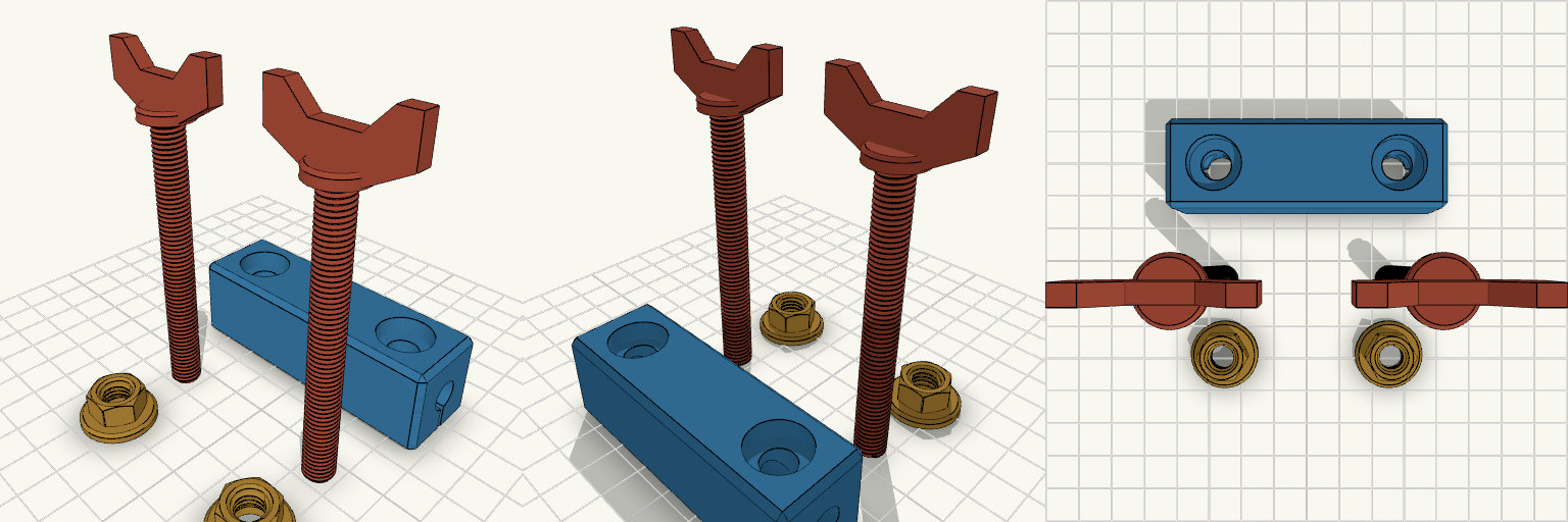
A clamp block that squeezes onto M8 threaded rod, with matching M8 × 1.25 wing screws and flanged nuts. The block is 76.2 mm (3 in) long and 24 × 24 mm in section, with an 8.4 mm bore running its full length; a slit through the lower half is closed by two screws at 25 mm either side of centre. It replaces a bought rod clamp and a pair of hand-tightened screws — everything on the plate is printed and then fitted together. Thread and fits M8 × 1.25 mm coarse thread throughout: the screw shank is threaded 8 mm, the nut bore carries the matching thread with 0.15 mm clearance so the pair turns together off the plate. Fine-pitch M8 × 1.0 will not match. M8 threaded rod, studding or 8 mm plain shaft in the bore. The bore is 8.4 mm with no give — measure your rod before printing. The flange pad under each nut has an 8.6 mm clearance hole, so only the hex section engages the thread and the pad bears flat on the work. The two bolt holes sit 50 mm apart (25 mm either side of centre, ±25 mm). Ordinary steel M8 × 1.25 hex screws and nuts will seat in the same counterbores and pockets if you would rather not print the hardware — though steel nuts come without the clamping pad, and the head counterbores are sized for hex heads, not the printed wing collars. What is on the plate Clamp Body — 76.2 × 24 × 24 mm, flat on the bed in the middle. M8 Screws — two off, each a 3 in (76.2 mm) threaded shank under a wing head: a round collar with two tapered wings, 34 mm tip to tip and 4 mm thick, about 92 mm overall. Laid out head up; the wings are flat plates, so if your slicer allows, stand each screw on its head with the shank up for the cleanest wing and thread. M8 Nuts — two off, each with a round 20 mm pad on its underside, 2.3 mm thick with a chamfered edge. Pads face the work when fitted. All pieces are separated with no overlaps, ready to print flat and assemble after. Check before printing The thread pair: matched at M8 × 1.25 but not test-fitted. If the printed screw and nut run too tight or too loose, the 0.15 mm clearance is the number to change. The screw length: a 3 in shank in the 24 mm block leaves about 52 mm of thread projecting below the body. Check that projection clears whatever sits under the clamp, and that the 34 mm wing head has room to turn once the thread is engaged. The 24 mm square section sets how far the clamp stands off its mounting surface — check it clears, and allow the 2.3 mm pad under each nut where the pad bears on the work. What it does not fit It is a rod clamp, not a nut clamp: it will not grip an M8 nut or bolt head in the bore. It does not suit 10 mm or 12 mm rod, and the bolt holes take M8 only — smaller screws will not seat in the counterbores or the nut pockets. Fine-pitch M8 × 1.0 hardware will not thread into these nuts. The pads are round, not square, and are sized only for the M8 pockets in this body.
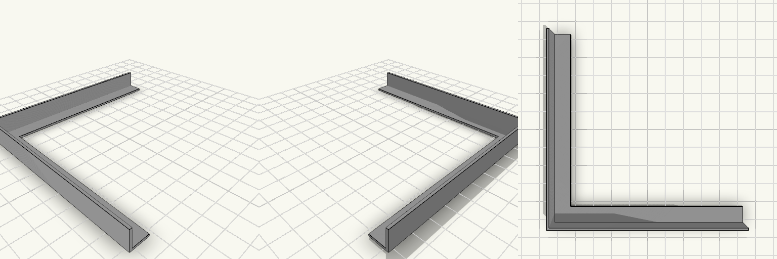
Canal en L con Paredes Altas
Una tira en L de 200 mm medidos por el centro, con dos brazos en ángulo recto, 10 mm de ancho y base de 1 mm. Las dos paredes exteriores, las más largas, se elevan 10 mm sobre la base y forman un canal de esquina abierto por dentro. Base: 1 mm de grosor Paredes exteriores: 1,2 mm de espesor, 10 mm por encima de la base Bordes interiores (más cortos): sin pared Altura total: 11 mm
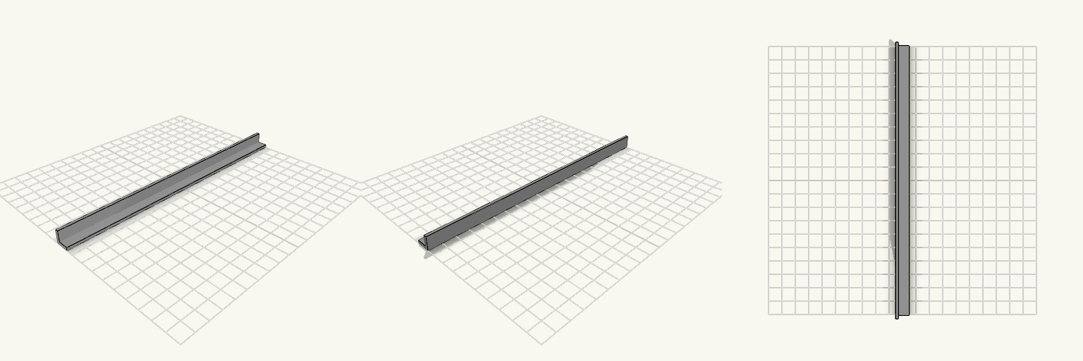
Ángulo — Tira en L de 20 cm
Ángulo — perfil en L de 20 cm de largo, pensado como esquinero, guía o refuerzo de bordes. Dos caras iguales a 90°, de sección sencilla y fácil de imprimir tumbado. Dimensiones Largo: 200 mm Ancho de cada cara: 10 mm Grosor: 2 mm Notas de impresión Imprimir apoyado sobre una cara, sin soportes. Para más rigidez, orientar las capas a lo largo del perfil.