CluckFlow — Gravity Waterer Cap
Created 1 months ago
Description
New chickens bring endless questions, but a reliable water supply doesn't have to be one of them. CluckFlow is a gravity-fed waterer cap that threads directly onto a standard bucket or heavy-duty jar, instantly converting it into an automatic hydration station for the coop. A smart internal drip-feed port regulates the flow from the main reservoir, ensuring the trough automatically refills as the hens drink without ever flooding.
Dimensions
- Trough: 40 mm continuous drinking width accessible from all sides.
- Central Feed Tube: 20 mm inner diameter.
- Collar Thread: 100 mm diameter with a 5 mm pitch, scaled for common bulk containers.
Design Features
- Print-in-Place: The internal bell funnel is steeply angled to bridge the gap between the central feed tube and the outer threaded collar, printing entirely without supports.
- Self-Regulating: Multiple drip ports ensure constant equalization of the water line.
Images
More like this
Explore more in Home & Fixtures →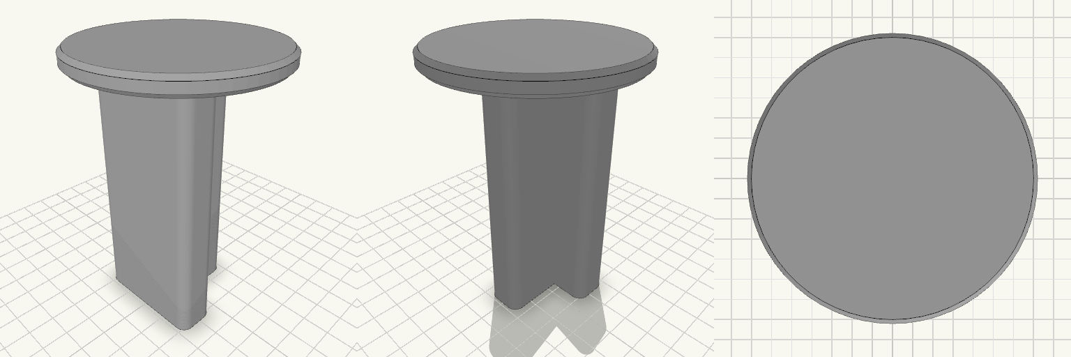
T-Post Cap With 3-Inch Round Platform
A slip-on cap for a steel T-post: 4 in tall, with a T-shaped socket that drops over the post and a 3 in round platform, 1/4 in thick, on top. Fits Steel T-posts, matched to the T-socket below. The socket is a T: a 36 mm crossbar, 7 mm wide at the stem entry, with a 7 × 30 mm stem running down, and a 4 mm wall following that T all the way around. Takes the place of a plain post cap and adds a flat, 3 in round surface on top of the post. Check before printing The socket is the whole fit, and its numbers are a starting size, not a standard — T-posts differ in flange width and web thickness between manufacturers and post weights. Measure the post you intend to use across the crossbar, across the stem, and across the full depth, then set the socket to those sizes plus a little clearance for paint and burrs before you commit filament. Nothing else on the part affects fitment. Does not fit Round posts, wooden 4x4 posts, or any post without a T cross-section. T-posts whose crossbar or stem is wider than the socket above — T-post profiles are not interchangeable, so do not assume a fit from the post name or the post weight alone. The cap prints as a single piece, 76 × 76 × 102 mm overall.
U-Turn — Zweiteilige 180°-Schlauchführung
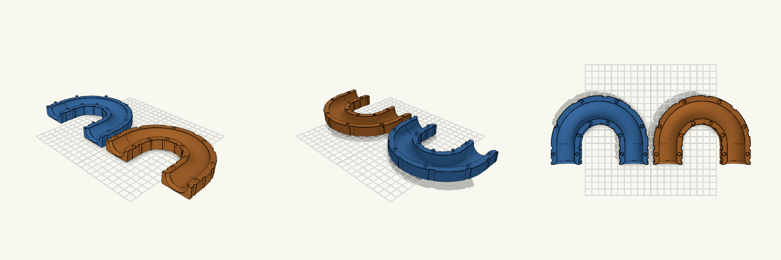
U-Turn ist eine zweiteilige 180°-Schlauchführung, die einen Schlauch mit 25 mm Außendurchmesser in einem gleichmäßigen Bogen umlenkt, sodass Ein- und Auslauf parallel nebeneinander in dieselbe Richtung zeigen. Statt Schrauben oder Muttern halten handelsübliche Kabelbinder die beiden Hälften zusammen: Mehrere außenliegende Nuten laufen um den gesamten Querschnitt, sodass die Binder nicht seitlich abrutschen und nicht in den Schlauchkanal hineinragen. Die flache Außenseite liegt beim Druck unten, die Nut zeigt nach oben — dadurch kommen beide Hälften ohne Stützmaterial aus. Maße Schlauchkanal: 26 mm Innendurchmesser für einen Schlauch mit 25 mm Außendurchmesser Bogen: exakt 180°, Biegeradius 50 mm zur Mittellinie, Mittellinien 100 mm auseinander Gerade Ein- und Auslaufstrecken: je 30 mm, an den Enden auf etwa 33 mm aufgeweitet Wandstärke: 4 mm; Querschnitt 42 mm breit, jede Hälfte 17 mm hoch Kabelbindernuten: 5,2 mm breit und 1,5 mm tief für 4,8 mm breite Binder; Restwand an der dünnsten Stelle 2,5 mm Aufbau Beide Hälften verlaufen über den gesamten 180°-Bogen und tragen je eine halbrunde Nut, die zusammengesetzt einen geschlossenen, kreisförmigen Kanal ergibt. Die Hälfte mit den Zapfen trägt Zapfen von 5 mm Durchmesser und 4 mm Höhe, die Gegenhälfte passende Aussparungen von 5,4 mm Durchmesser — das ergibt ein Montagespiel von 0,2 mm je Seite. Die Zapfen sitzen beidseitig des Kanals, sowohl auf dem Bogen als auch an den geraden Endstücken, und verhindern ein seitliches Verrutschen. Montage Die Hälfte mit den Aussparungen umdrehen, auf die Hälfte mit den Zapfen setzen und andrücken. Anschließend Kabelbinder durch die Nuten führen und festziehen: fünf Nuten verteilen sich gleichmäßig entlang des U-Bogens, je zwei sitzen an den geraden Endstücken. Druckhinweise Beide Hälften werden getrennt gedruckt und anschließend zusammengesteckt; die Kabelbinder übernehmen die Fixierung. Der Kanal ist an beiden Enden großzügig abgerundet, damit der Schlauch ohne Knickstellen ein- und ausläuft.
Cabinet Handl Bumper
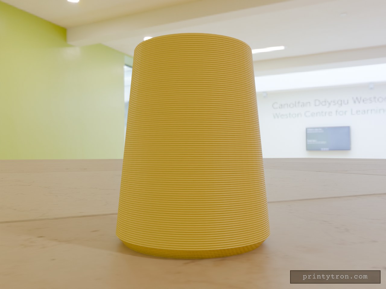
A cabinet handle end that slams into the door or wall now has a cone-shaped TPU bumper to take the hit. The bumper slides over the handle end and stays put on an 11.8 mm blind hole. Key numbers Height: 32 mm Base diameter: 26 mm, with a 1.5 mm 45° chamfer on the bottom edge Narrow end diameter: 20 mm Hole: 11.8 mm diameter, 24 mm deep, opening at the narrow end Print: TPU, base down, no supports needed
Charging Station Marker Nail
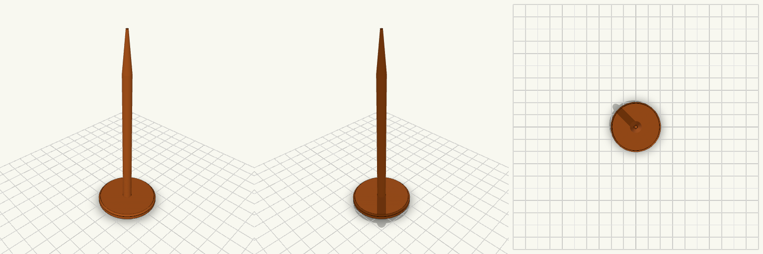
A ground marker nail for holding the position of a robot mower charging station while the charger is stored for the season. It is pushed into the soil where the charger's screw sits in summer. The nail has a wide, flat 40 mm head that stays visible at ground level, a slim 6 mm round shaft, and a tapered point for easy insertion. It prints head-down, so no supports are needed. Head: 40 mm diameter, 4 mm thick, chamfered edge Shaft: 6 mm diameter, about 90 mm long Tip: tapers to a point over 25 mm Overall length: about 119 mm Prints without supports
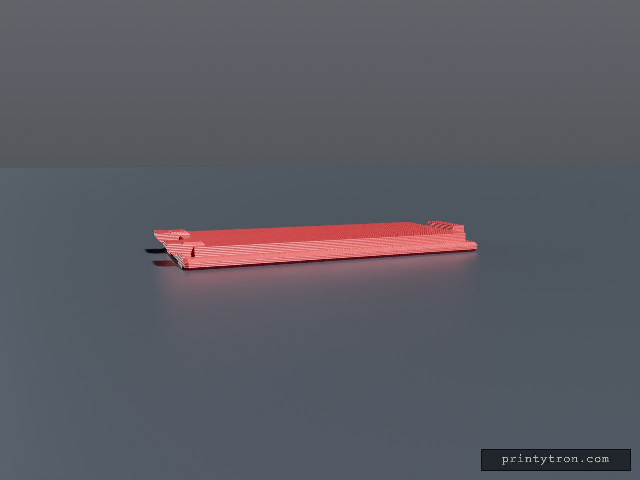
Bug Zapper Battery Cover 27.65 x 60 mm
Sliding battery compartment cover plate for a bug zapper, 27.65 x 60 mm. A locating lip sits in the compartment opening, a latch tab sits at one end, and two low retention tabs at the opposite end keep the cover from falling out. Plate: 27.65 x 60 x 2 mm, chamfered edges Lip: 23.65 x 56 mm, 3.8 mm total height Retention tabs: two, 5 mm wide, flush with lip height, at X = ±8 mm Latch tab: 10 mm wide at the +Y end Grip grooves on the outer face Dimensions are estimates; verify against the original opening
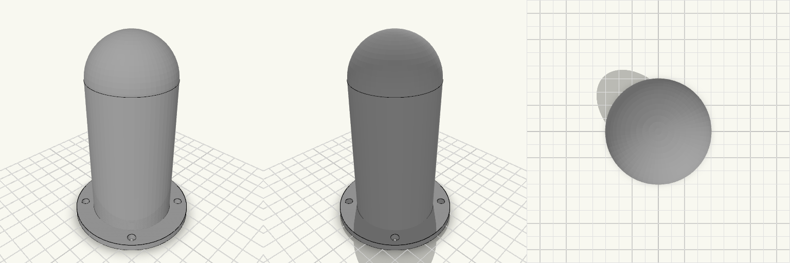
Antenna Cover With Mounting Flange
An antenna protective cover that keeps weather and knocks off the antenna: a hollow cylinder with a domed top, open at the bottom, on a flat bolt-down flange. Total height: 115 mm including the 4 mm flange Body: 50 mm outer, 46 mm inner diameter (2 mm wall), dome radius 25 mm blending tangentially into the cylinder Flange: 72 mm diameter, 4 mm thick Holes: four 5 mm through-holes in a square, 43.1 mm between adjacent centres Print: open end down on the flange, no supports needed, 3+ perimeters recommended