Flat Snap-In Interior Trim Cover
Created 19 days ago
Description
A removable interior trim cover with a flat front surface, a stepped outline (107 mm wide at the top, 123 mm at the bottom, 180 mm tall) and a soft raised area at the upper left. A rear locating frame and eight ratcheting snap clips hold it in the opening without screws.
Remix hooks
- Raised area height: 10 mm with a roughly 30 mm blend. Lower it for a subtler step, or delete it for a fully flat panel.
- Surface curvature: the panel is flat in both directions. A gentle crown can be added back by adding a term to the height function.
- Clip layout: four clips per side at 25, 65, 105 and 145 mm height, each with four ratchet teeth 3.5 mm apart. Change the tooth pitch to match the metal edge thickness.
- Stabilising grid: 20 mm pitch, 1.6 mm ribs, about 3.5 mm tall. Pitch and height are easy to adjust.
- Pairs with: fuzzy skin in the slicer for a textured plastic look, in PETG, ASA or ABS.
Images
More like this
Explore more in Automotive, RC & Hobby →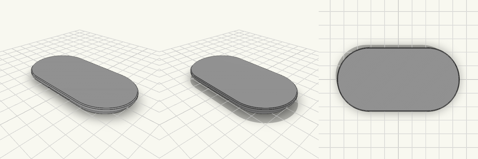
86x45mm Ovaler Karosserie-Blindstopfen mit Snap-Fit-Clips
Geschlossene ovale Abdeckplatte für eine 80 × 39 mm große Öffnung in etwa 1 mm dickem Karosserieblech. Die Kontur ist ein Stadion-Oval, also ein gerades Mittelstück mit vollständig runden Enden. Die Platte wird eingedrückt, die integrierten Snap-Fit-Clips federn zurück und rasten hinter dem Blech ein – ohne Schrauben, Kleber oder separate Befestigungsteile. Die Abdeckung lässt sich wieder entfernen, ohne das Blech zu beschädigen. Das Teil wird als ein Stück gedruckt. Frontplatte: 86 × 45 mm, 2 mm dick, vollständig geschlossen, gerundete Kanten; die 2 mm fallen an der gerundeten Kante etwas dünner aus Einsatz: Außenkante 80 × 39 mm, Endradius 19,5 mm, 4 mm tief, hohle Wand mit 1,6 mm Stärke Innenöffnung: 76,8 × 35,8 mm Flansch: rundum 3 mm breit, an den Längsseiten wie an den Enden; die Clip-Haken liegen vollständig innerhalb der Plattenfläche Clips: zwei Zungen an den Längsseiten oben und unten, je ein 0,7 mm hoher Haken mit Rampen-Anlauf und flacher Fangfläche für 1 mm Blech Clip-Schlitze: 1 mm breit × 6 mm lang durch die Wand der Längsseiten, geben den Zungen Platz zum Federn Passung: Die Außenkante des Einsatzes entspricht exakt 80 × 39 mm, es bleibt kein Spiel – straffer Sitz, vor dem Einbau einen Probedruck einplanen Einbauraum: Die Frontplatte misst 86 × 45 mm; vor dem Einbau prüfen, ob um die Öffnung herum genug Platz für 45 mm Höhe ist Material: PETG oder ASA, mit der Frontseite nach unten drucken Bauteilmaße auf der Druckplatte: 86 × 45 × 6 mm
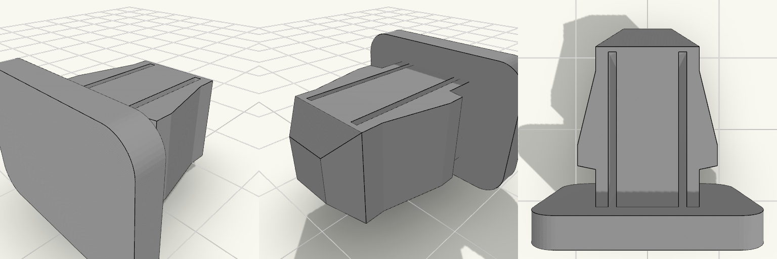
Push-In Trim Clip, Screwable Head
A dashboard-trim style push-in clip with a smooth, fully closed 22 x 16 mm rounded head and a solid central core that takes a self-tapping screw from the front. Head: 22 x 16 x 3 mm, rounded corners, no holes Shaft: 10 x 10 mm, about 18 mm long, chamfered insertion tip Two spring arms with tapered ramps and locking shoulders, 13.5 mm across the barbs Narrow slots separate the arms from the central screw core Best printed in PETG or ASA
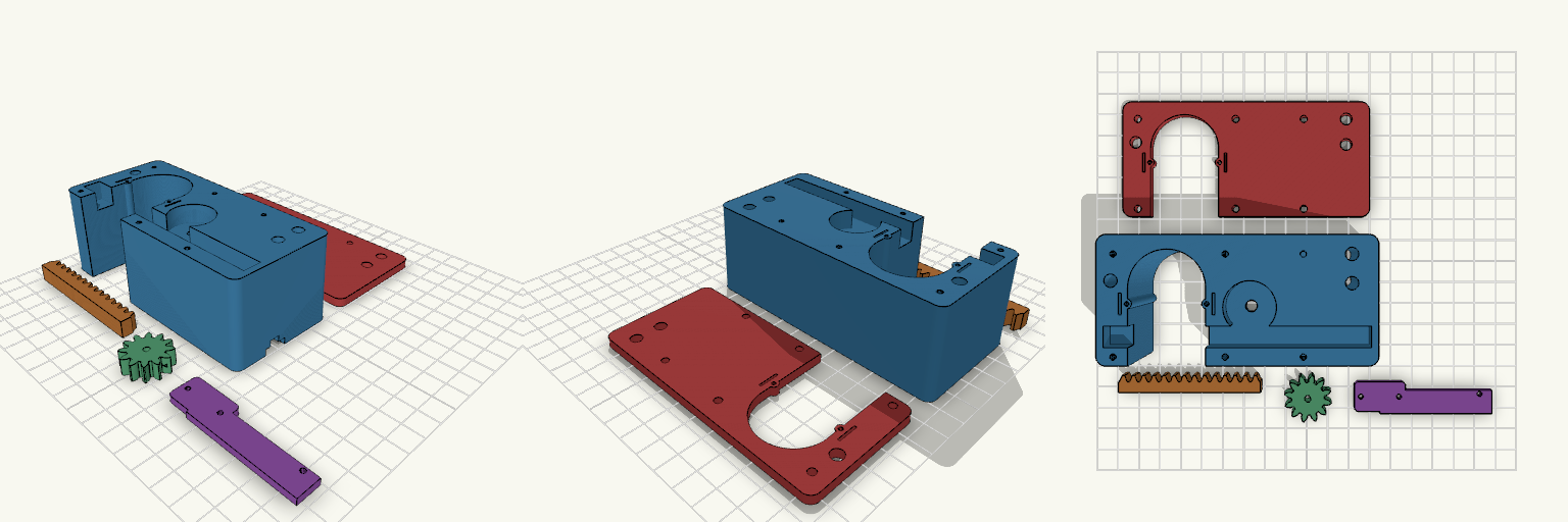
final version 25 mm Paddle Shaft
Motorised rack-and-pinion U-holder for a 30 mm paddle shaft, with hollow flexing snap detents on the slot walls. Fit Host: 30 mm round paddle shaft in a 32 mm slot; N20 gear motor, 12 × 10 mm body, 3 mm shaft. Detents: each slot wall has a hollow bump (1 mm radius through-hole) on a flex finger with a relief slit. The cover plate carries the same features. Not for: shafts other than about 30 mm, or motors with a different body size. Check before printing Measure the N20 body length including gearbox and terminals; the motor length is a parameter. Detent stiffness depends on the bump height and the hole radius. Adjust them for your filament. Parts Housing, sliding rack, pinion, motor retainer and cable cover (one piece), guide cover plate.
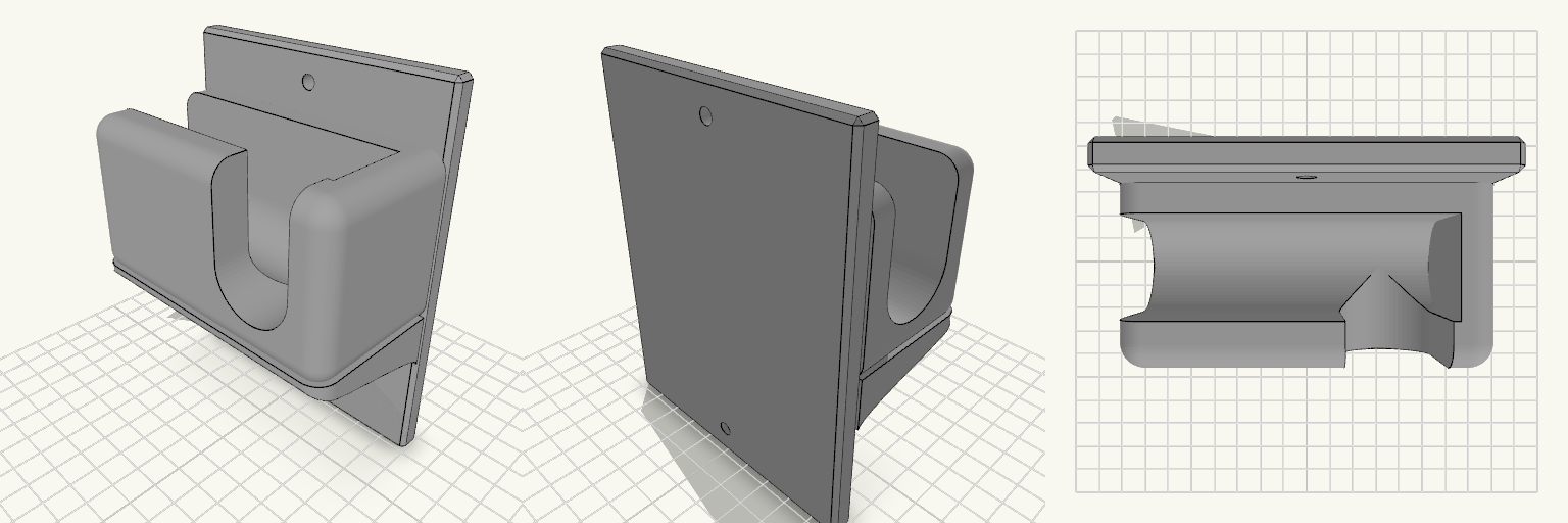
Wall-Mounted Jack Stand Hanger small support
A wall-mounted holder that keeps a 3-ton jack stand off the garage floor and within reach. The flat vertical back plate carries a U-shaped cradle in the centre, open at the top so the stand's bar drops in and lifts out. The cradle is open through the middle and closed by a 10 mm wall at each end, so the bar cannot slide sideways off the holder. The front wall of the cradle is a 13 mm lip that catches the bar and stops it sliding forward. The cradle walls are rounded with a 7 mm radius on every edge except the one against the back plate, and the inner floor is a rounded half-cylinder trough running the length of the opening, 28 mm across to match the seat, so a round bar or handle lies in it without rocking. The holder prints as one piece with no assembly, and it is sized for a 3-ton jack stand and its handle. A compact gusset supports the cradle underneath and runs the full 100 mm width of the cradle, so the end walls sit flush on it instead of overhanging. Its corners carry the same 7 mm radius as the cradle, so the walls run down into it with no ledge. The underside is an S-curve: it leaves the back plate 39 mm up, sweeps out and finishes running straight up the back of the front lip, meeting both surfaces tangentially so there is no crease where it joins. Keep it around this size — trimming it much further leaves the cradle with little support against the weight of a loaded stand. The jack handle hangs from two cuts, so it drops in from above rather than being threaded in from the front. A 28 mm slit in the front wall, open at the top, sits 24 mm right of centre and stays clear of the right edge, which runs fully to the front and stands even with the left wall. Opposite it, the left end wall carries a matching 28 mm notch, open at the top. Both cuts share the cradle trough's floor depth, with their centreline at 80 mm up and their floors bottoming out at 66 mm. The slit floor starts at the trough centreline with a rounded blend where the two meet, so the handle slides from the trough into the slit and notch without a step and hangs clear below. The cradle walls stand 55 mm tall, topping out at 110 mm up, which leaves about 16 mm of wall above a 28 mm handle resting at 80 mm. Overall: 100 mm wide, 130 mm tall, 57 mm deep Cradle: U-shaped, 28 mm bar seat, open top, open through the middle, 10 mm end wall each side, rounded floor trough Cradle walls: 55 mm tall, tops at 110 mm, rounded at 7 mm Bar opening: about 80 mm between end walls Front lip: 13 mm thick Handle slit: 28 mm, open at the top, set 24 mm right of centre in the front wall, floor blended into the trough Left end wall: matching 28 mm notch, open at the top, for the other side of the handle Floor height: slit, notch and trough all bottom out at 66 mm Gusset: full cradle width, 7 mm rounded corners, S-curve underside tangent to the back plate and the front lip, meeting the plate 39 mm up Mounting: one countersunk screw hole above the cradle and one below; use 5 mm or larger screws into a stud or suitable anchor Material: grey PETG suits the load and garage conditions; edges are chamfered Check that the stand's bar fits the 28 mm seat and the 80 mm opening, and that the handle fits the 28 mm slit and notch before printing. If the bar or handle is larger, widen the seat or the cuts to match.
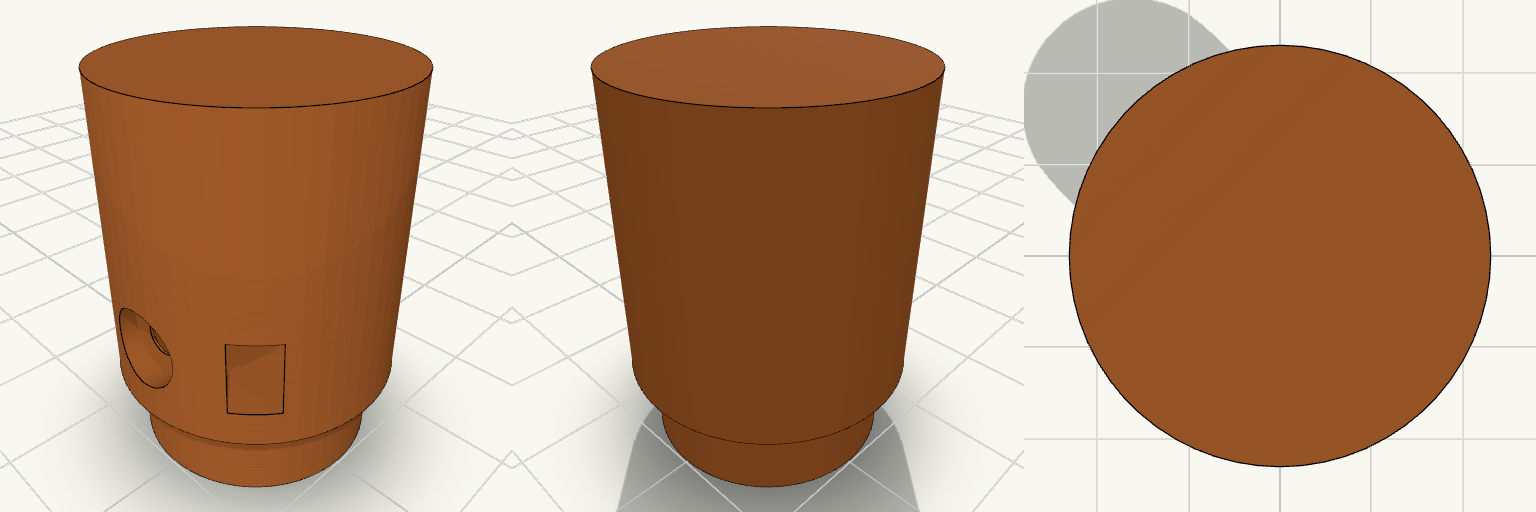
Pinch-Feed Drive Roller, Print-Ready
A knurl-free drive wheel for a pinch-feed wire feeder, built like a small industrial pulley: a 24 mm roller with a hub on one side and a blind D-bore that slips over a 5 mm D-shaft. The model is just the roller, standing on its hub and ready to slice. Design notes Blind D-bore, open on the hub face and closed by a wall on the far end, so the closed end shows which side stays out. M3 grub screw hole with a trapped hex nut that slides in through a slot open to the rim. Counterbored screw recess 2 mm deep, so a headed M3 screw sits below the surface and a nylon or TPU sleeve goes on smooth. Hub spaces the roller off the motor face so the two do not rub. Printing Stands on the hub with the bore opening onto the bed, so there is no bridging inside the bore and no supports are needed. Printing upright keeps the roller round. Suggested: PETG, ASA or nylon, 3 or more walls, 25–30% infill.
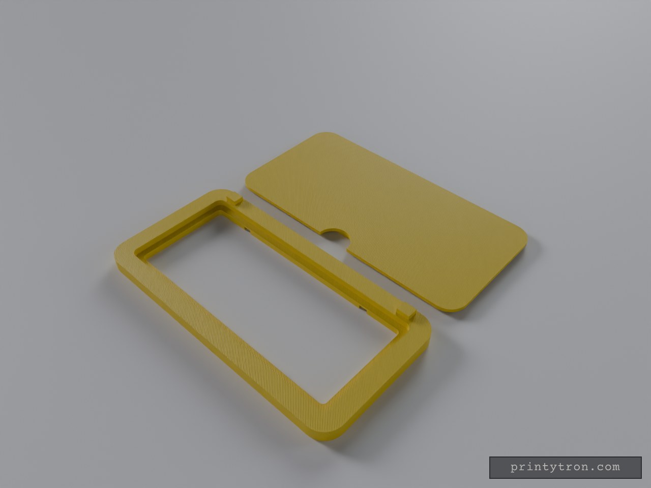
Slim Sun Visor Mirror Frame
A flat, rounded-corner frame for a sun visor vanity mirror, with a separate thin protective lid. Glass is supplied by you. Body: 130 x 65 x 6 mm, 9 mm corner radius Glass pocket: 114 x 50 mm, 3 mm deep Rear strap slots: two slots for a hook-and-loop or elastic strap around the visor, so no clips show Lid: 1.8 mm plate with an underside lip that press-fits into the pocket, plus a front thumb notch Printed as two separate pieces, no supports needed when printed flat Adjust the pocket size to match your glass before printing.