DataStack — Enclosure Core
Created 1 months ago
Description
A lightweight, 4-bay enclosure body for 2.5" SATA HDDs.
Features
- Stripped-down chassis with extensive material-saving cutouts
- Integrated rails for 4 drives
- Rear bosses for mounting a custom PCB backplane
Designed to be printed on end (resting on the back faces) to avoid internal supports.
Images
More like this
Explore more in Desk & Tech →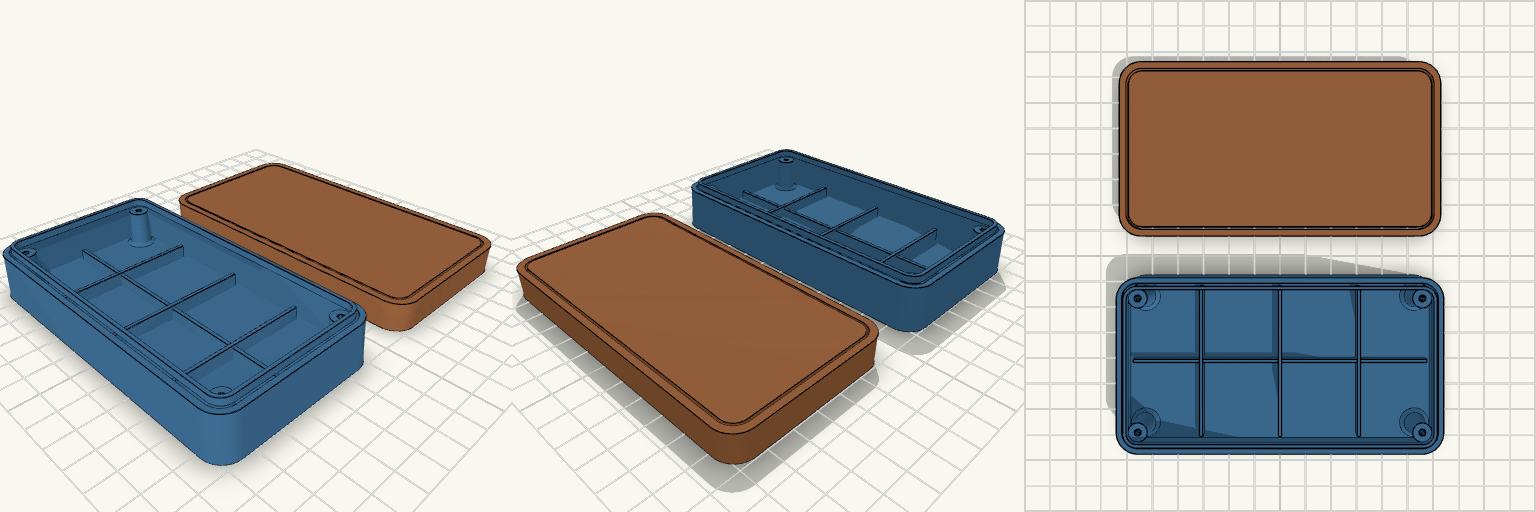
Bakelite-Era Two-Piece Electronics Enclosure
A compact two-piece case with a vintage Bakelite silhouette: rounded corners, softly drafted walls, and a clean split line between the lower housing and the upper cover. At 120 × 65 × 28 mm, it gives a small board or module a protected home, with a hollow internal cavity, four corner screw bosses, reinforcement ribs, and a tongue-and-groove closing lip. The enclosure prints as two separate pieces, with the cover laid beside the housing so both print without supports. Design notes Lower Housing: the deeper shell, with corner bosses, internal ribs, and a raised closing tongue. Upper Cover: the lid, with a matching groove and clearance holes for the screws. Walls and corners: 2 mm walls, 8 mm outer corner radius, and a 1.5° draft on the outer shell and lip. Screw bosses: four corner bosses with 2.6 mm pilot holes in the housing and 3.2 mm clearance holes in the cover. Printing: separate upper and lower parts, oriented to avoid supports.
Vertical Switch Dock Stand with Strap Slots
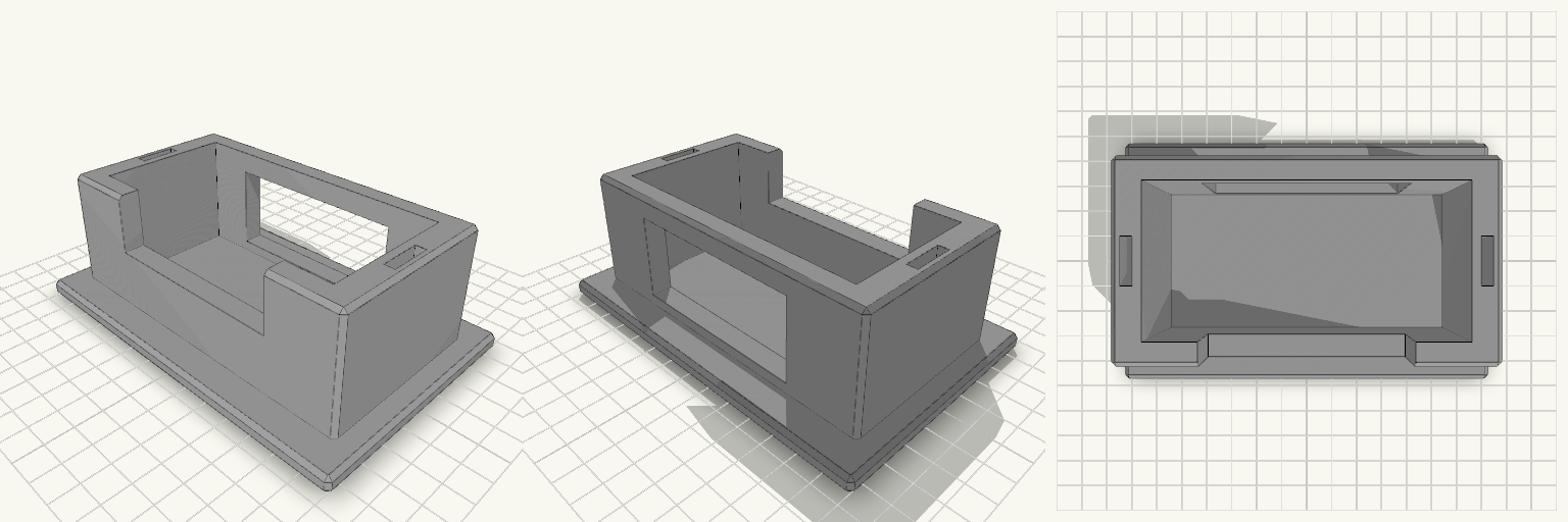
A Switch dock lying flat eats shelf space, and a dock stood on its end tips over the first time someone pulls a cable. This stand holds the dock upright in a snug pocket on a wide flat base, and keeps two spare Joy-Con straps in slots in the side walls. What it does Holds the dock on its end so it takes up a footprint of about 142 × 92 mm instead of its full 175 mm length lying down. Front wall is cut down in the middle, so you can grip the dock to lift it out. A 70 mm opening in the back wall lets the power, HDMI and USB cables leave without bending against the stand. Two 4 × 16 mm slots, one in each side wall, hold spare Joy-Con straps. Numbers that decide fit Pocket: 106 mm wide × 52 mm deep, for a dock of roughly 104 × 49 mm. That leaves about 1 mm of play on width and 3 mm on depth. Pocket depth: 44 mm, above a 6 mm base. Overall: 142 × 92 mm base, 50 mm tall. Side walls: 10 mm thick. Front and back walls: 8 mm. Printing Print flat on the base, with no supports needed. Chamfered edges, 1.5 mm. Any common filament works. PETG or PLA is fine for the load. If your dock is a tight fit or loose, adjust the pocket width and depth to match.
SilentSOS Two-Piece Electronics Enclosure
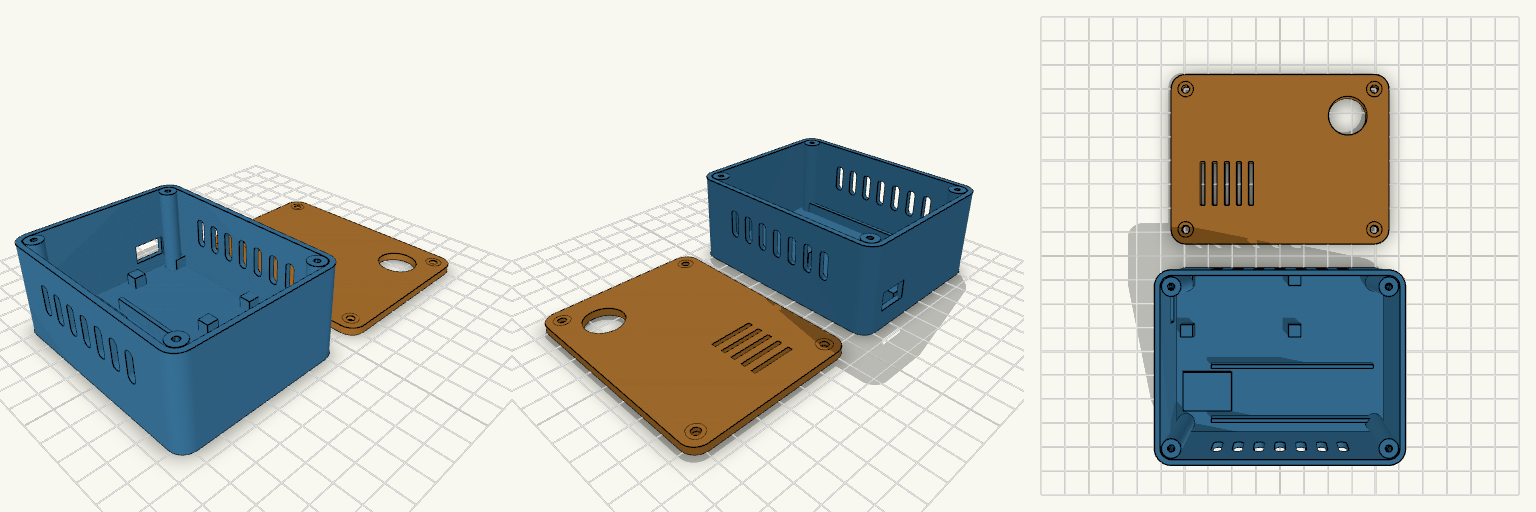
A 90 × 70 × 40 mm two-piece enclosure for an ESP8266 NodeMCU SOS alert device: a 37 mm tall base with 2 mm walls and a separate 3 mm lid, with 6 mm rounded vertical corners. The lid is printed flat and fastens with four M3 screws into corner bosses. Remix hooks Component mounting: no hole positions were guessed. The NodeMCU sits on four 5 mm locating pads at the board corners (49 × 26 mm area, nb, nbc). Once measured, add real standoffs in extraposts as [x, y] pairs and set post_pilot. Battery bay: two 1.5 mm rails 22 mm apart hold a cell of about 18 mm diameter, 65 mm long. Move or space them for other cells. DC-DC zone: a low 20 × 16 mm pad, free to move or resize. USB opening: 13 × 8 mm in the short wall, aligned to the NodeMCU position. SOS button: 16 mm hole in the lid (btnd, btnpos). Ventilation: seven slots in each long wall plus five slots in the lid. Screws: 2.6 mm pilots in the bosses, 3.4 mm countersunk lid holes. Pairs well with heat-set inserts in the bosses, or a gasket strip for a dust-resistant fit. Export base and lid as separate STLs by rendering each module alone.
Crossfader Knob 20x8x10 mm
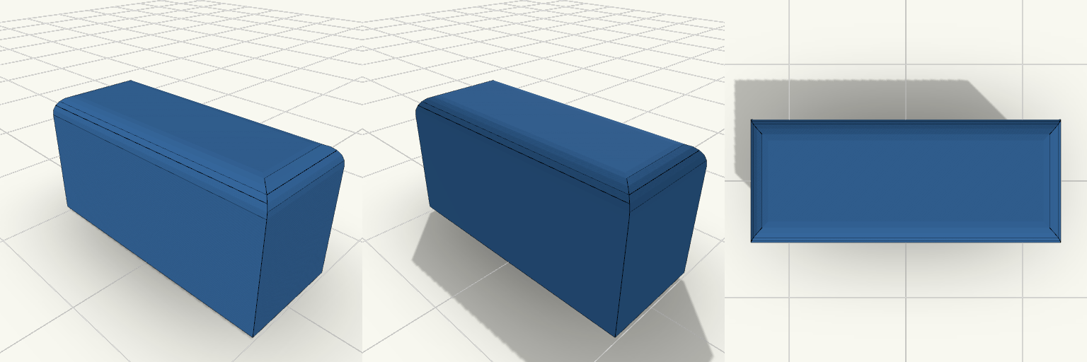
What it's for A solid rectangular crossfader knob for a DJ controller, with a centred socket underneath that fits over the fader stem. The socket's long side now runs across the knob width (Y). Dimensions Knob: 20 × 8 × 10 mm, top edges rounded 1.5 mm. Socket: 1.5 × 4.0 mm stem plus 0.1 mm clearance per side, 6 mm deep, with a small lead-in chamfer. The stem size is a placeholder; adjust stemw and stemt to match the real fader. Remix ideas Swap the socket for a D-shaped or round stem. Add grip ridges on the top face. Increase the height for a taller handle.
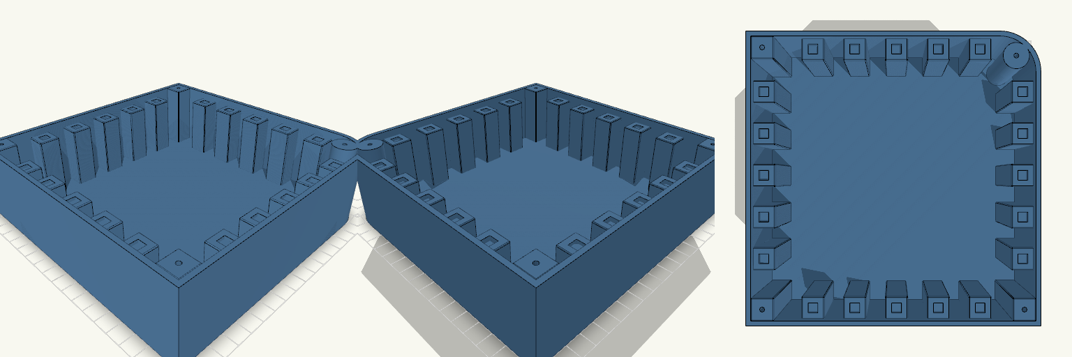
Arecson — Base con Pilares de Pulsador
Arecson es una base de caja de 180 × 180 × 50 mm con una sola esquina redondeada, pensada para un controlador DJ. Cuatro pilares de esquina, uno de ellos cilíndrico en la curva, permiten atornillar la tapa, y una fila de cinco pilares sostiene pulsadores de 6 mm. Características Caja de una pieza, sin tapa, con suelo plano. Pilares de esquina de 50 mm con guía de 3 mm y 30 mm de profundidad. Cinco pilares de 14 × 14 × 45 mm en fila horizontal en la zona inferior. Asiento de 6,1 mm y 2 mm de profundidad en cada pilar. Notas de impresión Si el pulsador entra justo, subir el asiento a 6,2 mm.
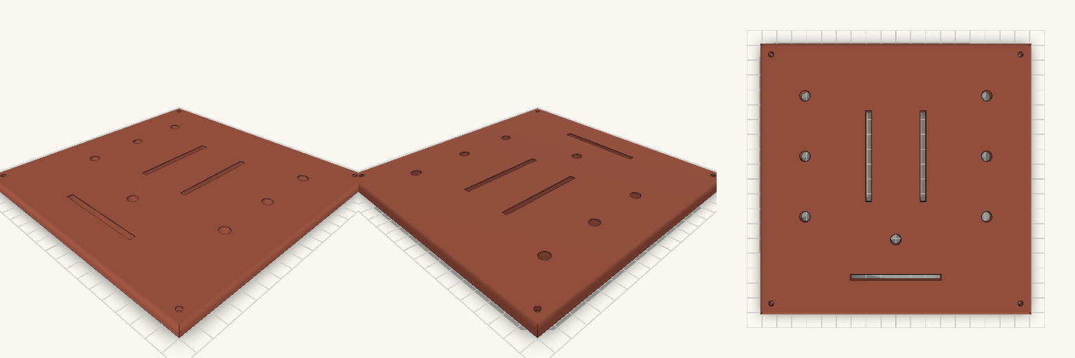
Tapa 180x180 con 3 crossfaders y 7 potenciómetros
Tapa de 180 × 180 × 5 mm para un controlador DJ, con tres ranuras de crossfader y siete agujeros de potenciómetro de 7 mm. Medidas a comprobar Ranuras de crossfader: 60 × 4 mm (el largo total del recorte según la ficha de tu modelo). Agujeros de potenciómetro: 7 mm, seis a ±60 mm en X y uno central en X = 0, Y = −40 mm. Cuatro tornillos M3 avellanados en las esquinas. No incluye Taladros de fijación de los crossfaders ni de los potenciómetros.