Tapa 180x180 con 3 crossfaders y 7 potenciómetros
Created yesterday
Description
Tapa de 180 × 180 × 5 mm para un controlador DJ, con tres ranuras de crossfader y siete agujeros de potenciómetro de 7 mm.
Medidas a comprobar
- Ranuras de crossfader: 60 × 4 mm (el largo total del recorte según la ficha de tu modelo).
- Agujeros de potenciómetro: 7 mm, seis a ±60 mm en X y uno central en X = 0, Y = −40 mm.
- Cuatro tornillos M3 avellanados en las esquinas.
No incluye
- Taladros de fijación de los crossfaders ni de los potenciómetros.
Images
More like this
Explore more in Desk & Tech →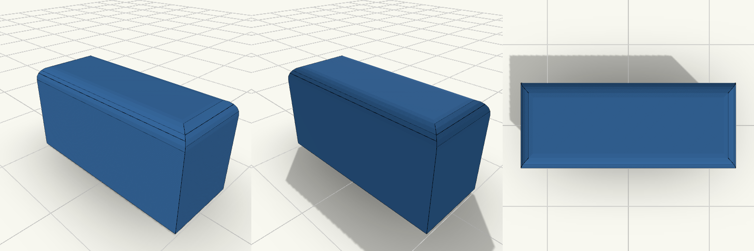
Crossfader Knob 20x8x10 mm
What it's for A solid rectangular crossfader knob for a DJ controller, with a centred socket underneath that fits over the fader stem. The socket's long side now runs across the knob width (Y). Dimensions Knob: 20 × 8 × 10 mm, top edges rounded 1.5 mm. Socket: 1.5 × 4.0 mm stem plus 0.1 mm clearance per side, 6 mm deep, with a small lead-in chamfer. The stem size is a placeholder; adjust stemw and stemt to match the real fader. Remix ideas Swap the socket for a D-shaped or round stem. Add grip ridges on the top face. Increase the height for a taller handle.
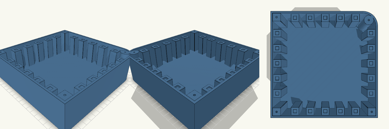
Arecson — Base con Pilares de Pulsador
Arecson es una base de caja de 180 × 180 × 50 mm con una sola esquina redondeada, pensada para un controlador DJ. Cuatro pilares de esquina, uno de ellos cilíndrico en la curva, permiten atornillar la tapa, y una fila de cinco pilares sostiene pulsadores de 6 mm. Características Caja de una pieza, sin tapa, con suelo plano. Pilares de esquina de 50 mm con guía de 3 mm y 30 mm de profundidad. Cinco pilares de 14 × 14 × 45 mm en fila horizontal en la zona inferior. Asiento de 6,1 mm y 2 mm de profundidad en cada pilar. Notas de impresión Si el pulsador entra justo, subir el asiento a 6,2 mm.
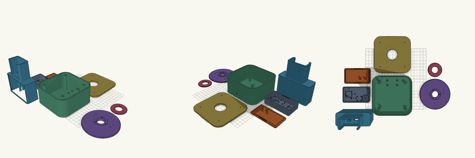
Modular Voice Assistant Enclosure with Rotating Desk Dock
A two-part enclosure system for a modular AI voice assistant: a pocket-sized "Brain" that works on its own, and a desktop station that docks it, swivels a full 360° and carries a 3.5-inch touchscreen behind a removable bezel. Both halves share the same matte-black design language — rounded corners, smooth surfaces and 2–2.5 mm walls — and print as eight separate pieces. What it's for Brain — houses an ESP32-S3 N16R8 board, an INMP441 I2S microphone, a MAX98357A amplifier and a 20 mm speaker behind a grille. A circular LED ring glows through a 0.8 mm front skin for listening, thinking and speaking states; there is no display of its own. A USB-C port sits on the short end, and the unit runs standalone once lifted off the dock. Desk station — a weighted base with a bolted lid carries a swivel plate and the dock tower. The Brain drops into the tower pocket from above with its face still visible, and a USB-C plug cradle in the pocket floor lines up with the port. Display — the tower front takes a standard 98 × 56 mm touchscreen module in landscape, held on four M2 bosses and framed by a bezel that drops into a recess in the front face. Removing four screws frees the display for replacement, and a flat-cable slot below the opening routes the ribbon into the cavity. Rotation — the swivel plate's hollow stem passes through the lid, a retaining ring screws on underneath, and the cable runs down the centre of the stem, so the tower turns 360° without twisting the lead. Dimensions Brain: 85 × 50 × 25 mm overall, with a snap-fit rear cover. Desk base: 120 × 120 mm with 22 mm corner radii; base, lid and swivel plate stack to 65 mm. Dock tower: 104 × 40 × 119 mm, docking the Brain vertically above the display section. It overhangs the 100 mm swivel plate slightly at the front and rear corners. Display opening: 84 × 54 mm, with mounting bosses behind the wall at ±46 × ±25 mm and M2 pilot holes; bezel 100 × 60 × 2.5 mm. Walls: 2–2.5 mm throughout hollow cavities. Print notes Print the Brain shell face-down for a smooth front skin; the LED ring, microphone port and speaker grille all sit in that face. The rear cover snaps on with two bump-and-groove pairs along the long sides; pads on its inside hold the ESP32 down. The tower's internal floor and the display window bridge wide spans, so expect a little support in the dock tower only. Everything else is oriented to print without it. Print the bezel flat; it is a thin frame and needs no supports. PLA or PETG both work; four rubber-foot recesses under the base are worth filling. All eight pieces — Brain shell, rear cover, desk base, base lid, swivel plate, retaining ring, dock tower and display bezel — are separate. The lid bolts on at four corners and the display bezel screws in from the front. Compatibility The display bosses use M2 pilot holes; check your module's hole spacing before driving screws, since pinouts vary between boards. The dock pocket is sized for the Brain as drawn — if you change the Brain's shell, adjust the pocket in step. Remix ideas Lean the dock back a few degrees for a more natural viewing angle if you can accept the extra support. Swap the removable bezel for a blank panel or a vent if your build has no screen. Scale the docking pocket to fit a different companion device while keeping the same swivel mechanism.
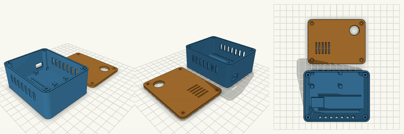
SilentSOS Two-Piece Electronics Enclosure
A 90 × 70 × 40 mm two-piece enclosure for an ESP8266 NodeMCU SOS alert device: a 37 mm tall base with 2 mm walls and a separate 3 mm lid, with 6 mm rounded vertical corners. The lid is printed flat and fastens with four M3 screws into corner bosses. Remix hooks Component mounting: no hole positions were guessed. The NodeMCU sits on four 5 mm locating pads at the board corners (49 × 26 mm area, nb, nbc). Once measured, add real standoffs in extraposts as [x, y] pairs and set post_pilot. Battery bay: two 1.5 mm rails 22 mm apart hold a cell of about 18 mm diameter, 65 mm long. Move or space them for other cells. DC-DC zone: a low 20 × 16 mm pad, free to move or resize. USB opening: 13 × 8 mm in the short wall, aligned to the NodeMCU position. SOS button: 16 mm hole in the lid (btnd, btnpos). Ventilation: seven slots in each long wall plus five slots in the lid. Screws: 2.6 mm pilots in the bosses, 3.4 mm countersunk lid holes. Pairs well with heat-set inserts in the bosses, or a gasket strip for a dust-resistant fit. Export base and lid as separate STLs by rendering each module alone.
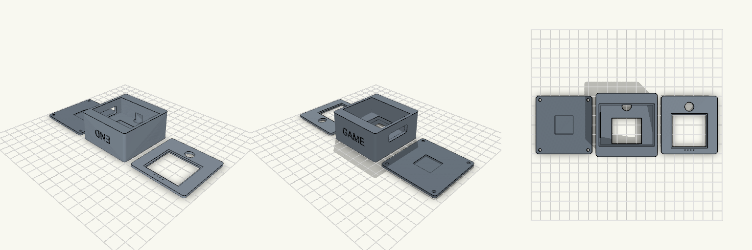
Lockdown — Dev Board Case With Camera Eye
Lockdown is a three-part enclosure for a Freenove ESP32-S3 WROOM CAM board with a 35.5 × 33.5 mm display. The front bezel turns the screen into a face, with a 9.6 mm camera eye above the window. The side wall carries one wide cable opening, so USB-C plugs and cables pass straight through the housing. Features 58 × 60 mm footprint across chassis, back cover and bezel Screen pocket with a support ledge and a flex-cable opening 9.6 mm camera bore lined up with the bezel eye Single 26 × 9 mm cable pass-through on the +X wall, raised for a high-mounted board Four M3 screws from the back Embossed-in END and GAME text on the end walls Print notes Print the three parts flat on their backs. PETG works well.
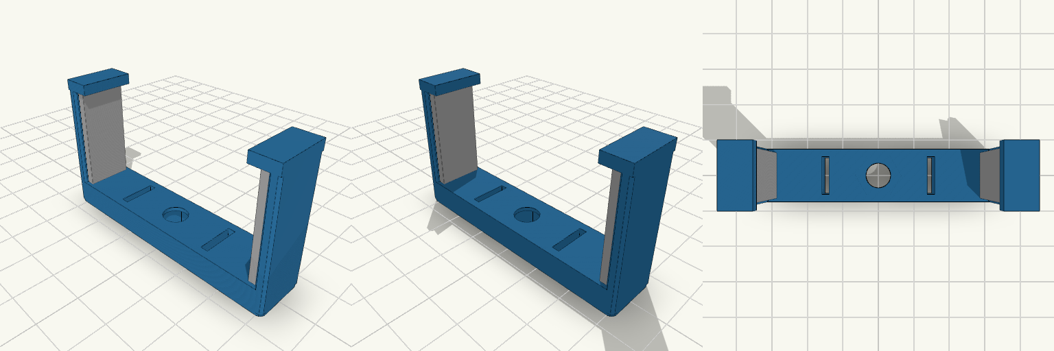
Phone Clamp 60-85mm with 1/4-20 Socket
U-shaped spring clamp that holds a phone across its back and bolts to the centre screw of a ring light. The two jaws grip the phone's long edges. The rest opening is 58 mm and the jaws flex to about 85 mm. Separate soft pads sit on the inner faces to protect the phone's edges. The base has a 1/4-20 through hole with a hex nut pocket on the underside. Two slots cut into the base give the jaws room to spring. Each jaw ends in a retaining lip that stops the phone from lifting out. Specs Opening: 60-85 mm, 58 mm at rest Mount: 1/4-20 through hole (6.6 mm) with a 12.2 mm hex nut pocket Jaw thickness: 2.6 mm Jaw width: 22 mm Overall size: about 63 x 14 x 36 mm Clamp body material: PETG suggested, for spring flex Pad material: TPU suggested, printed as separate pieces Spring travel: not tested, so check the flex before loading a phone Use cases: ring light phone mount, filming, content creation setups