Horizontal LCD Control Enclosure
Created 1 months ago
Description
A horizontal electronic project enclosure designed for control panels and desktop instruments. The assembly features an internal mounting frame for a standard 1602 LCD module and four 12mm tactile push buttons. Components install from the underside of the top cover, ensuring that only the display area and button caps are visible from the exterior.
The two-part construction secures together using four M3 screws with captured hex nuts embedded in the bottom housing.
- Overall dimensions: 220mm × 140mm × 60mm
- Hardware required: 4× M3 screws, 4× M3 hex nuts
- Component mounts: 1602 LCD PCB (80x36mm) and 4× 12mm tactile switches
- Print orientation: Both parts print flat on the build plate without supports
Images
More like this
Explore more in Desk & Tech →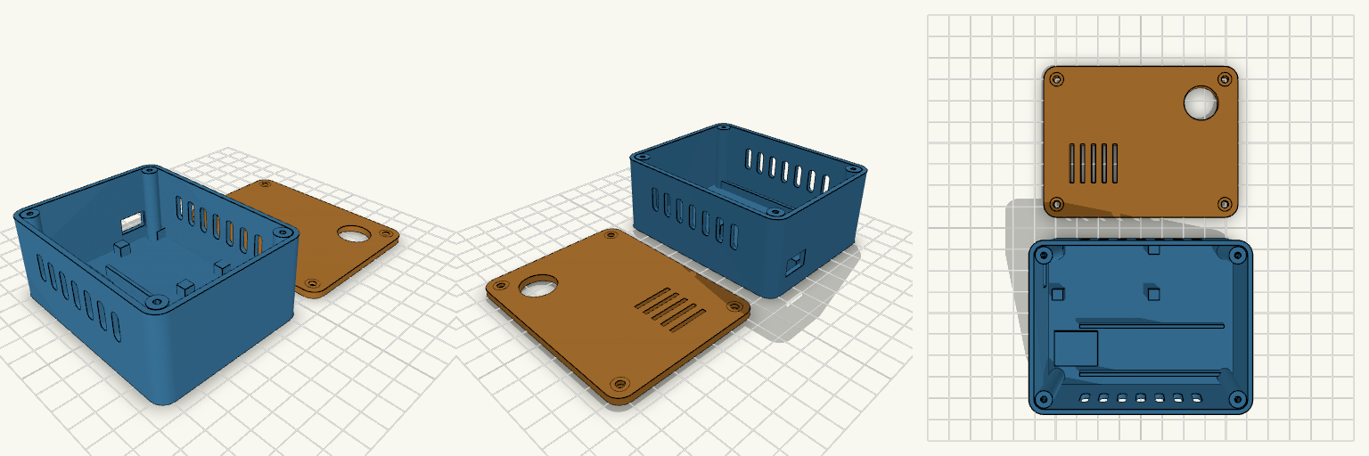
SilentSOS Two-Piece Electronics Enclosure
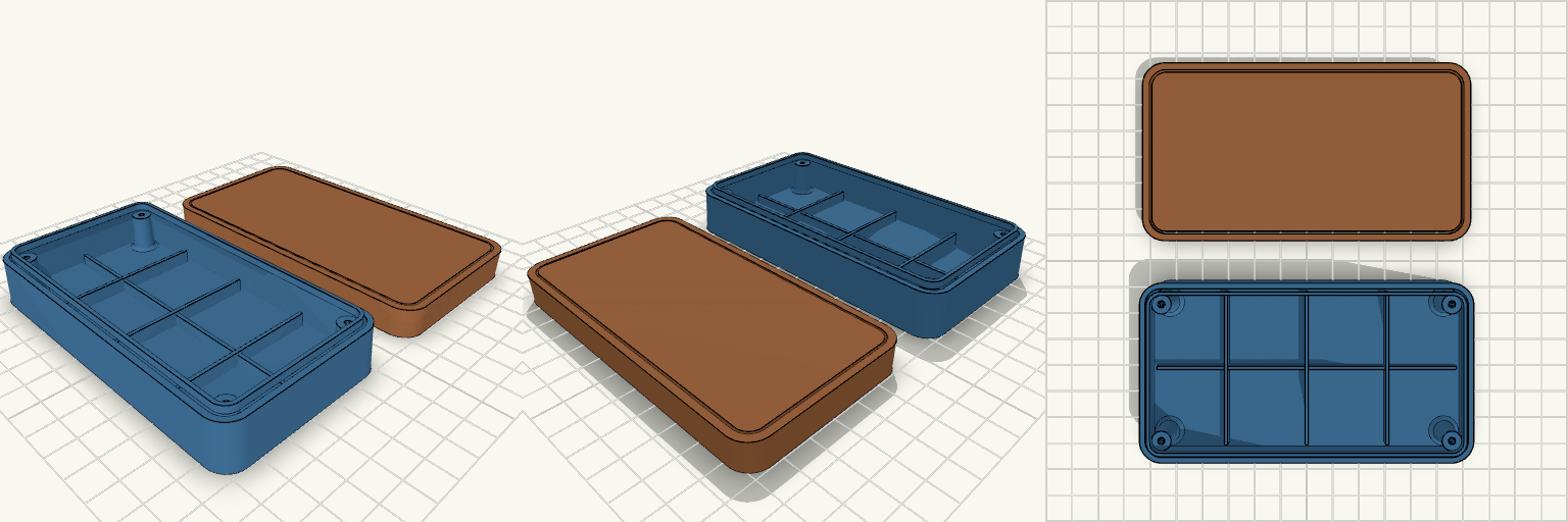
A 90 × 70 × 40 mm two-piece enclosure for an ESP8266 NodeMCU SOS alert device: a 37 mm tall base with 2 mm walls and a separate 3 mm lid, with 6 mm rounded vertical corners. The lid is printed flat and fastens with four M3 screws into corner bosses. Remix hooks Component mounting: no hole positions were guessed. The NodeMCU sits on four 5 mm locating pads at the board corners (49 × 26 mm area, nb, nbc). Once measured, add real standoffs in extraposts as [x, y] pairs and set post_pilot. Battery bay: two 1.5 mm rails 22 mm apart hold a cell of about 18 mm diameter, 65 mm long. Move or space them for other cells. DC-DC zone: a low 20 × 16 mm pad, free to move or resize. USB opening: 13 × 8 mm in the short wall, aligned to the NodeMCU position. SOS button: 16 mm hole in the lid (btnd, btnpos). Ventilation: seven slots in each long wall plus five slots in the lid. Screws: 2.6 mm pilots in the bosses, 3.4 mm countersunk lid holes. Pairs well with heat-set inserts in the bosses, or a gasket strip for a dust-resistant fit. Export base and lid as separate STLs by rendering each module alone.
Bakelite-Era Two-Piece Electronics Enclosure
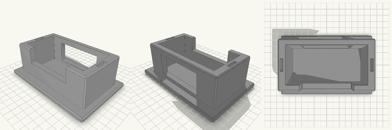
A compact two-piece case with a vintage Bakelite silhouette: rounded corners, softly drafted walls, and a clean split line between the lower housing and the upper cover. At 120 × 65 × 28 mm, it gives a small board or module a protected home, with a hollow internal cavity, four corner screw bosses, reinforcement ribs, and a tongue-and-groove closing lip. The enclosure prints as two separate pieces, with the cover laid beside the housing so both print without supports. Design notes Lower Housing: the deeper shell, with corner bosses, internal ribs, and a raised closing tongue. Upper Cover: the lid, with a matching groove and clearance holes for the screws. Walls and corners: 2 mm walls, 8 mm outer corner radius, and a 1.5° draft on the outer shell and lip. Screw bosses: four corner bosses with 2.6 mm pilot holes in the housing and 3.2 mm clearance holes in the cover. Printing: separate upper and lower parts, oriented to avoid supports.
Vertical Switch Dock Stand with Strap Slots
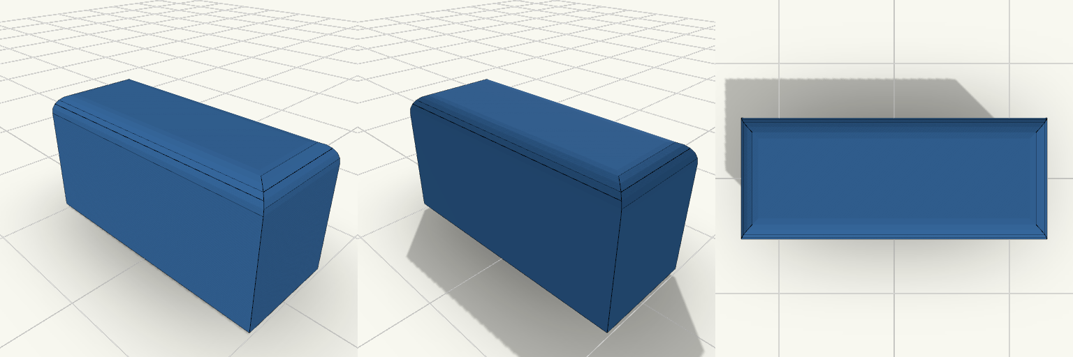
A Switch dock lying flat eats shelf space, and a dock stood on its end tips over the first time someone pulls a cable. This stand holds the dock upright in a snug pocket on a wide flat base, and keeps two spare Joy-Con straps in slots in the side walls. What it does Holds the dock on its end so it takes up a footprint of about 142 × 92 mm instead of its full 175 mm length lying down. Front wall is cut down in the middle, so you can grip the dock to lift it out. A 70 mm opening in the back wall lets the power, HDMI and USB cables leave without bending against the stand. Two 4 × 16 mm slots, one in each side wall, hold spare Joy-Con straps. Numbers that decide fit Pocket: 106 mm wide × 52 mm deep, for a dock of roughly 104 × 49 mm. That leaves about 1 mm of play on width and 3 mm on depth. Pocket depth: 44 mm, above a 6 mm base. Overall: 142 × 92 mm base, 50 mm tall. Side walls: 10 mm thick. Front and back walls: 8 mm. Printing Print flat on the base, with no supports needed. Chamfered edges, 1.5 mm. Any common filament works. PETG or PLA is fine for the load. If your dock is a tight fit or loose, adjust the pocket width and depth to match.
Crossfader Knob 20x8x10 mm
What it's for A solid rectangular crossfader knob for a DJ controller, with a centred socket underneath that fits over the fader stem. The socket's long side now runs across the knob width (Y). Dimensions Knob: 20 × 8 × 10 mm, top edges rounded 1.5 mm. Socket: 1.5 × 4.0 mm stem plus 0.1 mm clearance per side, 6 mm deep, with a small lead-in chamfer. The stem size is a placeholder; adjust stemw and stemt to match the real fader. Remix ideas Swap the socket for a D-shaped or round stem. Add grip ridges on the top face. Increase the height for a taller handle.
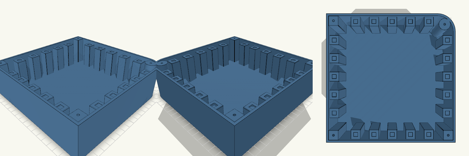
Arecson — Base con Pilares de Pulsador
Arecson es una base de caja de 180 × 180 × 50 mm con una sola esquina redondeada, pensada para un controlador DJ. Cuatro pilares de esquina, uno de ellos cilíndrico en la curva, permiten atornillar la tapa, y una fila de cinco pilares sostiene pulsadores de 6 mm. Características Caja de una pieza, sin tapa, con suelo plano. Pilares de esquina de 50 mm con guía de 3 mm y 30 mm de profundidad. Cinco pilares de 14 × 14 × 45 mm en fila horizontal en la zona inferior. Asiento de 6,1 mm y 2 mm de profundidad en cada pilar. Notas de impresión Si el pulsador entra justo, subir el asiento a 6,2 mm.
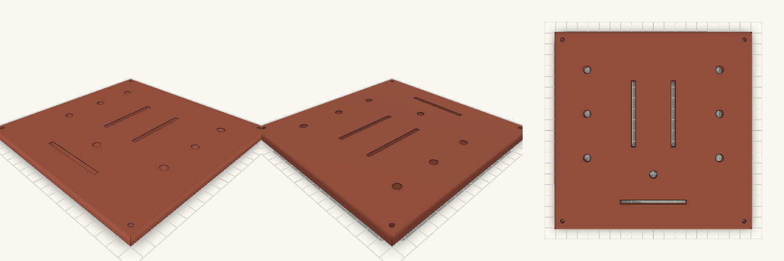
Tapa 180x180 con 3 crossfaders y 7 potenciómetros
Tapa de 180 × 180 × 5 mm para un controlador DJ, con tres ranuras de crossfader y siete agujeros de potenciómetro de 7 mm. Medidas a comprobar Ranuras de crossfader: 60 × 4 mm (el largo total del recorte según la ficha de tu modelo). Agujeros de potenciómetro: 7 mm, seis a ±60 mm en X y uno central en X = 0, Y = −40 mm. Cuatro tornillos M3 avellanados en las esquinas. No incluye Taladros de fijación de los crossfaders ni de los potenciómetros.