Mini-Server-Box with Feet, Lid and Fan (more stable)
Made by ConcreteLynx
Created 3 days ago
Description
What it's for
A closed-side enclosure for hiding and cooling equipment. All four side walls are solid, so the box stays dark and quiet from the sides. Airflow passes through the mesh grid in the floor and the mesh fan opening in the lid. A 30 × 20 mm cable hole in the lower rear corner lets wiring in and out, and the flat lid lifts off for access.
The model prints as separate pieces: the box, the lid and four feet. The lid is a plate with a locating lip underneath that sits well inside the box, and it overhangs the walls slightly so it can never drop in. The 140 mm fan opening is filled with a square-hole grid, keeping the full opening size while adding stiffness. Each foot carries its own coarse threaded stud, so the feet screw directly into threaded holes in the floor bosses with no separate fasteners.
Dimensions
- Box: 250 × 200 × 120 mm outside, with 4 mm walls and floor and a 242 × 192 mm cavity. Solid on all four sides, with a 30 × 20 mm cable opening in the rear wall kept clear of ribs.
- Wall ribs: vertical ribs on the inside faces, 3 mm thick and standing about 4 mm proud of the walls, running from the floor up to the lid recess. They are spaced about every 40 mm on the long walls and every 50–60 mm on the short walls, and stop clear of the cable opening and the foot posts.
- Floor mesh: sized to the narrower floor and ending where the foot posts and screw holes begin. The openings are 10 mm on a 12 mm pitch.
- Lid: 254 × 204 × 9 mm overall, with a 4 mm plate. Underneath, two lengthwise and two crosswise ribs, each 3 mm wide and 3 mm high, sit inside the lip so the lid still seats the same way. The locating lip follows the inner wall with roughly 5.5 mm of play per side and is 5 mm tall so it reaches into the box; its lower edge is chamfered to guide it in.
- Fan opening: 140 mm across, filled with a grid of 12 mm square holes on a 15 mm pitch, leaving 3 mm bars. The four fan screw holes are on a 124.5 mm square and cut through the lid plate. Check this against your actual fan before printing.
- Feet: four 24 mm discs, 18 mm tall including a 6 mm thick, 8 mm long threaded stud; 1.5 mm pitch, matching the threaded floor bosses. The set measures 114 × 24 × 18 mm laid out.
Print notes
- Print the box, lid and feet separately.
- The wall ribs are straight verticals, so they need no supports or overhangs. The lid ribs are shallow and bridge cleanly.
- Print the lid lip-side up so its flat face sits on the bed and the lip rises clear of the plate.
- The 4 mm walls, floor and lid plate rely on perimeter count and the ribs for stiffness, so wall count matters more than infill. With walls this thin, flex will go up a little; the wall ribs matter more now.
- Give the floor mesh and fan grid enough perimeters to keep the bars sturdy.
- The threads have not been test-fitted; if the feet bind, raise the socket diameter slightly, and if they wobble, lower it.
Suggested PETG settings (0.4 mm nozzle)
- Layer height: 0.2 mm for a clean surface, 0.3 mm to cut print time substantially; keep the first layer at 0.25–0.3 mm for adhesion. Print the feet at 0.16–0.2 mm so the threads come out clean.
- Wall lines: 3 lines for the box and lid with the 4 mm walls; 3 for the feet.
- Ribs and grid bars: 3 mm thick, so enable thin-wall detection so they print solid rather than with gaps.
- Top/bottom layers: 4 each at 0.3 mm layer height; 4–5 each at finer layer heights.
- Infill: 12–15% gyroid or cubic is enough given the nearly solid walls; raise it only if the box still feels soft.
- Speed: outer walls around 35–40 mm/s, inner walls 50–60 mm/s, infill 60–80 mm/s.
- Temperatures: 235–245 °C nozzle, 70–80 °C bed, part fan at 30–50% for good layer bonding. Use a brim on the box if corners lift.
Remix ideas
- Add a removable filter frame behind the fan grid.
- Add internal standoffs or a shallow tray for mounting equipment inside.
- Resize or duplicate the rear cable port for thicker cable bundles.
- Add a second row of wall ribs for even stiffer walls with the 4 mm walls.
- Change the fan grid bar thickness or hole pitch to trade airflow for stiffness.
- Swap the floor grid for a denser or more open pattern to change the airflow.
Images
More like this
Explore more in Desk & Tech →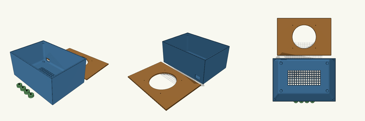
Mini-Server-Box with Feet, Lid and Fan
What it's for A solid-walled enclosure for hiding and cooling equipment. Every side wall is closed, and the only airflow path is a sturdy grid cut into the floor, so the box stays dark and quiet from the sides. A 30 × 20 mm cable hole in the lower rear corner lets wiring in and out, and the flat lid lifts off for access. The model prints as separate pieces: the box, the lid and four feet. The lid is a flat plate with a locating lip underneath, slightly larger than the box on every side so it overhangs and can never drop inside. Each foot carries its own coarse threaded stud, so the feet screw directly into matching threaded holes in the floor bosses with no separate fasteners. Dimensions Box: 290 × 200 × 130 mm, with 4 mm walls, solid on all four sides, an 8 mm floor, and a 50 mm solid border around the floor grid. The floor grid is centred on the narrower floor. The thicker floor makes the mesh bars deeper, so airflow per opening drops slightly. Inside fillets: 10 mm radius on the vertical corners and the floor-to-wall edges, stopping 15 mm below the rim. The top 15 mm stays square so the lid and its lip fit without changes. Lid: 294 × 204 mm, 9 mm overall with a 5 mm plate and underside lip; overhangs the box by 2 mm on all sides; 140 mm fan opening and four 3 mm fan screw holes at 124.5 mm center-to-center. Cable hole: 30 × 20 mm in the rear wall, set 20 mm from the left edge and 12 mm above the bottom, inside the solid section so it doesn't weaken the corners. Feet: four solid 24 mm discs, 10 mm tall, each with a 6 mm thick, 8 mm long threaded stud on top; 18 mm overall. The studs use a 1.5 mm pitch. Foot sockets: four corner bosses widened to 14 mm, with threaded holes 6.6 mm across and 11 mm deep at the same 1.5 mm pitch, giving about 0.6 mm clearance on diameter. Print notes Print the box, lid and feet separately. Print the lid lip-side up so its flat face sits on the bed and the lip rises clear of the plate. The floor grid benefits from enough perimeters to keep the bars sturdy. The threads have not been test-fitted; if the feet bind, raise the socket diameter slightly, and if they wobble, lower it. Test-fit the fan and check its screw-hole spacing before committing to a full print. Remix ideas Add a removable filter frame behind the fan opening. Add internal standoffs or a shallow tray for mounting equipment inside. Resize or duplicate the rear cable port for thicker cable bundles. Swap the floor grid for a denser or more open pattern to change the airflow.
Square-to-Round Fan Duct With Spout
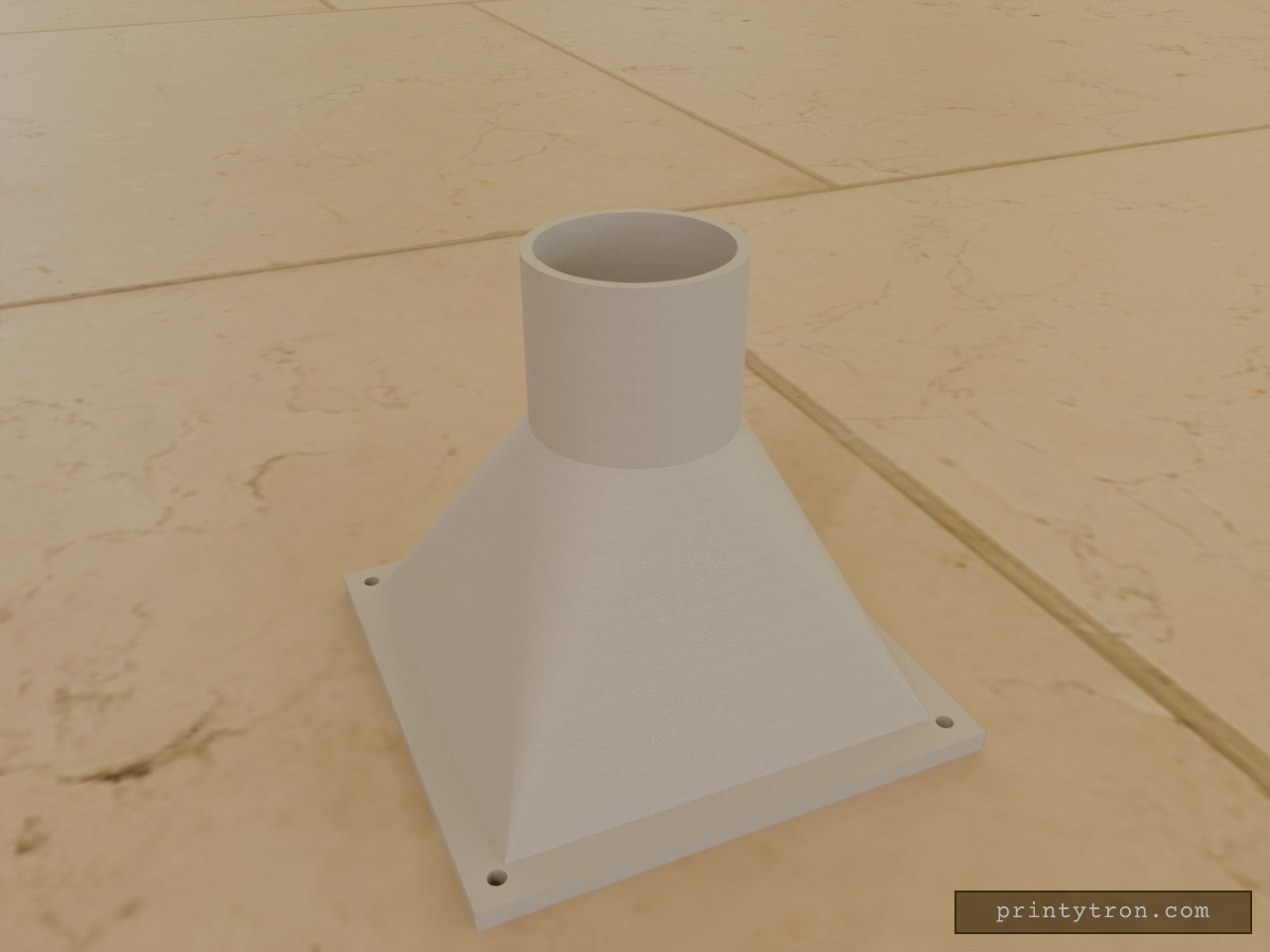
A fan-shroud adapter in the spirit of a classic blower nozzle: a flat square flange that funnels up into a round outlet, then runs straight like a spout. 92.5 mm square flange, 4 mm thick, with four M3 clearance holes on an 82.5 mm pitch (5 mm from each edge) 75 mm square inlet 50 mm square-to-round transition 30 mm straight round tube, 32 mm inner diameter, 36 mm outer 2 mm walls, no chamfers, prints flange-down in PLA without supports
Slot-Together Geared Tablet Stand, Doogee U11
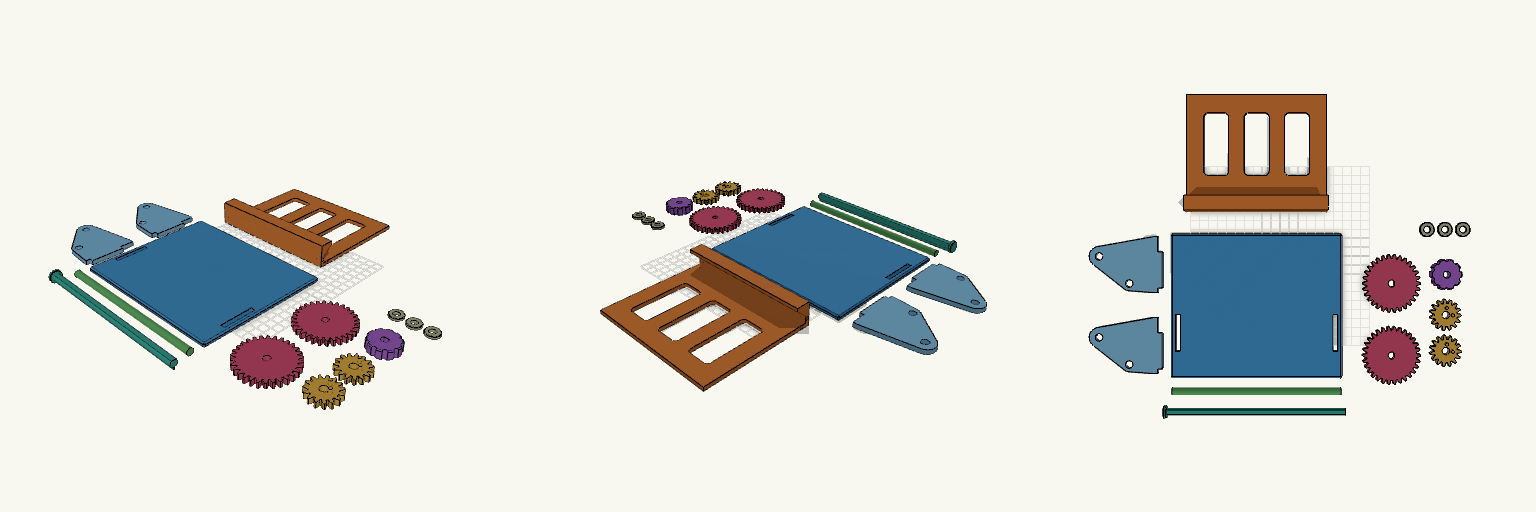
Geared tilting tablet stand for the Doogee U11, laid out as 14 separate flat pieces for printing and assembled by hand after printing. A knob on a drive shaft turns two 30-tooth gears that mesh with 15-tooth gears on the cradle, so a small knob twist tilts the cradle forward or back. Pieces Base plate: 1 Side plates: 2, with tabs that drop into slots in the base Tablet cradle: 1 15-tooth cradle gears: 2, peg into the cradle ends 30-tooth drive gears: 2, keyed to the drive shaft Knob: 1 Axle: 1, 8 mm round Drive shaft: 1, D-profile Friction-fit caps: 3 Print notes Every piece is laid flat on the build plate with no overlap. Gear pegs face up and the shaft flat faces down, so no supports are needed for the main bodies. Clearances are about 0.2-0.4 mm; adjust for your printer. Gear mesh and fit are untested; friction alone holds the tilt angle.
Octobay — 5.25" to 3.5" Drive Cage
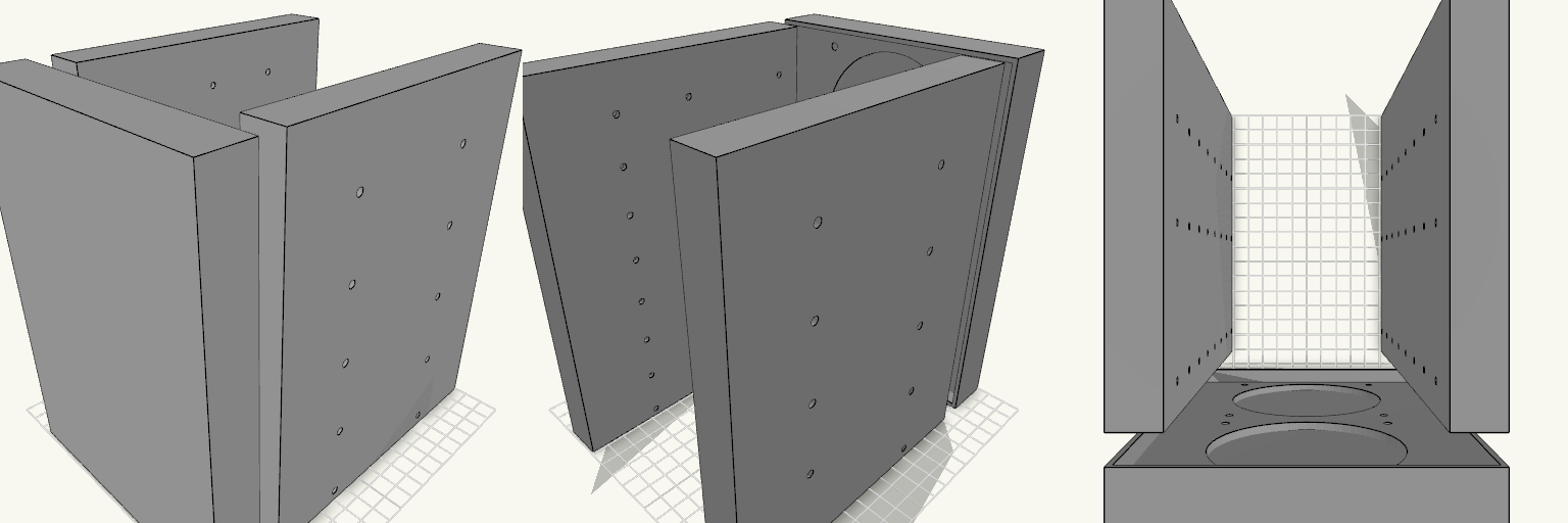
Octobay turns a five-bay stack of half-height 5.25" slots into room for eight 3.5" drives, and adds a 25 mm front cage that carries two 92 mm fans. The outer side faces take M3 heat-set inserts, so the whole cage screws into the case's 5.25" rails instead of resting on them. Everything is one printed part: the drive stack, the side mounting blocks and the fan cage print as a single body. Because the fans close off the front, drives now load from the back. The fan cavity behind the grille is hollow, so air still passes through to the drive stack. Dimensions Overall: 145 mm wide × 197.5 mm deep × 205.5 mm tall Fits: five half-height 5.25" bays Holds: eight 3.5" drives, stacked vertically Drive channel: 102.6 mm wide — 1 mm of play around a 101.6 mm drive Mounting 20 insert holes, 10 per side, for M3 heat-set inserts — 4.2 mm across and 6 mm deep Two insert holes per bay, at 41.3 and 117.5 mm from the front, 6.35 mm above each bay floor Solid blocks sit behind each hole to give the inserts something to bite into Three M3 screw holes per side per drive, at 14, 76.6 and 117.6 mm from the front Cross ribs sit clear of the screw holes so a screwdriver can reach every fastener Fan cage Two 92 mm fans, stacked vertically on the 25 mm front section 88 mm fan openings with 4.4 mm screw holes on the standard 82.5 mm square pattern Hollow cavity behind the fans feeds air to the drive channels Print notes Drive channels are open at the back, top and bottom, and the gaps between the inner and outer side walls are open for cable routing. Screw and insert positions and the 205.5 mm height follow common 5.25" bay standards; they have not been checked against a specific case, so measure your bay rails and drives before printing.
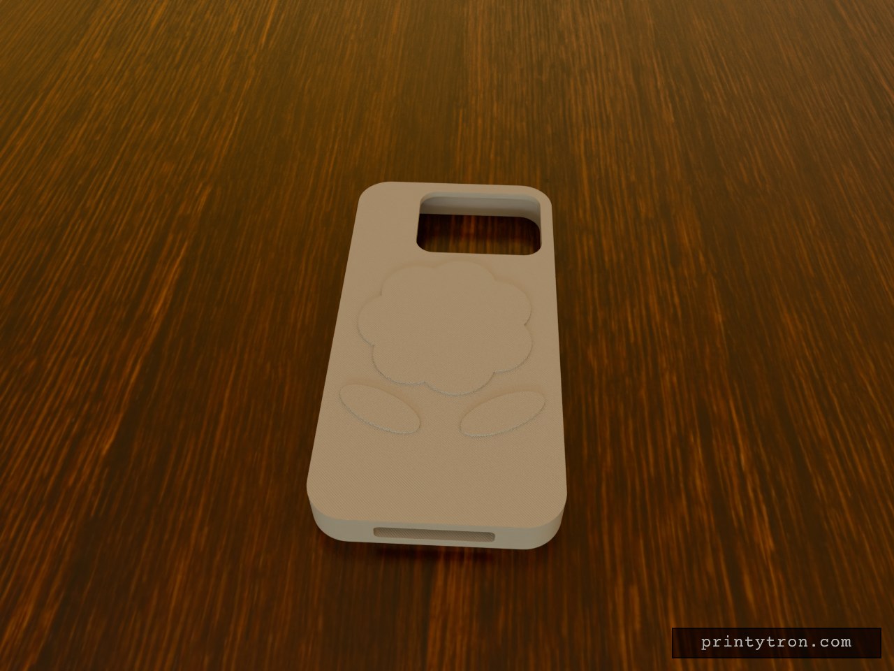
iPhone 17 Pro Max Case, Blue with Rose
What it's for A protective case for the iPhone 17 Pro Max in light blue, with a raised rose on the back below the camera cutout. Dimensions Phone body: 163.4 × 78 × 8.75 mm, with 0.3 mm of play per side Walls 4 mm, back 3 mm Rose relief: 1 mm, flat-topped layers Remix ideas Recolour the rose in blue tones to blend with the case Make the rose taller or soften its edges Swap the rose for another motif
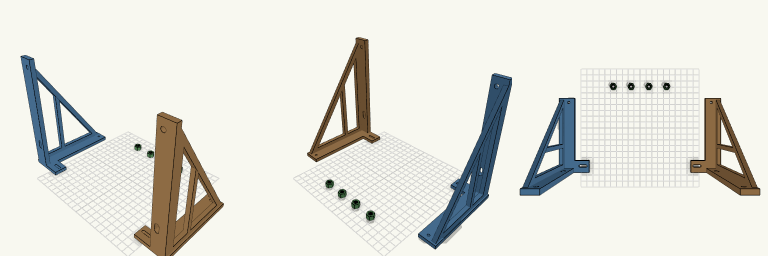
Tromba Perch — Due Staffe Laterali
Tromba Perch è una coppia di staffe laterali indipendenti per una tromba 220x160 mm con interasse fori di 240 mm. Senza traversa centrale, ogni staffa si avvita sul monitor con la propria base e regge un lato della tromba. Si risparmia materiale e ogni pezzo entra facilmente nel piatto di stampa. Features Interasse fori tromba invariato: 240 mm in orizzontale, 126 mm in verticale Pilastro allargato verso l'esterno fino a filo del triangolo Triangolo a telaio con montante di irrigidimento Base da 125 mm con fori di fissaggio anteriori (asole regolabili) e posteriori Fori tromba da 6,4 mm per perni M6, foro basso asolato per regolare l'inclinazione In the box Staffa sinistra Staffa destra 4 dadi M6 da 7 mm, stampati a parte Print notes Le due staffe sono pezzi separati, senza giunto Filettatura stampata in PLA fragile: per carichi veri meglio dadi metallici