Description
Minecraft ore lamp
Photos
Technical views
More like this
Explore more in Home & Fixtures →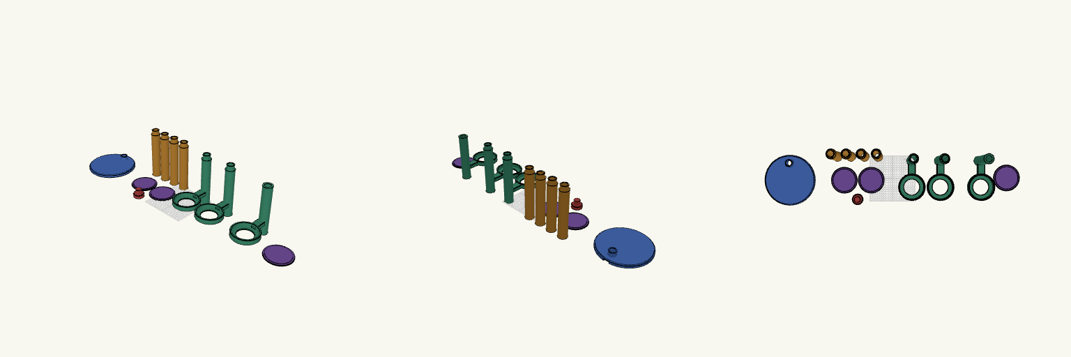
1.5 m Corner Lamp with Three Lamp Trays
A 1.5 m floor lamp for a room corner, built around a round 240 mm base and a hollow central pole. Three arms extend toward the room at different heights, each ending in a round cradle for a disc-style LED lamp of the kind used for model lighting. The lamps drop in face-down and shine through the opening in the floor of each cradle, and each holder has a removable top cover. The lamp prints as separate parts: a round base, hollow pole sections, three arm sections, a top cap and three lamp covers. The parts are laid out as separate pieces in four groups, each group fitting inside a 250 mm bed, so each one can be sent to its own plate in the slicer. Every part is at most 230 mm tall, so build height is not a limit. The pole sections push together with spigot-and-socket joints; dry-fit first, then glue once the fit is checked. Cables run inside the 26 mm bore in the pole and out through a groove under the base to the back edge. Build plates: four groups — base; four pole sections with two covers and the top cap; two arm sections; top arm section with the third cover Base: round disc 240 mm across and 14 mm thick, with a 3 mm chamfer and a plug for the first pole section Overall height: 1500 mm Pole: hollow sections, each 210 mm long, with a 26 mm bore for cables Arm heights: about 480, 900 and 1320 mm Cradle: 104 mm pocket, 114 mm outer ring, 17 mm deep, 70 mm floor opening Cover: 114 mm disc with 100 mm lip, removable, print flat with the lip up Cable route: 20 × 9 mm arm channel, cable notch in the rim, 24 mm exit groove under the base Printing: arm sections need supports under the arm and tray Assembly: push-fit joints with 0.3 mm clearance; glue after checking the fit Each cradle has a 104 mm pocket inside a 114 mm outer ring, with a 70 mm floor opening that lets the light out. The pocket and floor ring seat the lamp; the removable cover is a 114 mm disc with a 100 mm lip that sits inside the pocket. The cradles are sized around a disc-style lamp roughly 100 mm across; check the actual lamp diameter and thickness before printing. Each arm has a 20 × 9 mm internal channel that opens into the pole bore and runs to the cradle, sized to pass a USB plug. The disc base fits a 250 mm plate with about 5 mm to spare on each side, so check your slicer's plate margins before committing the print. The cradles reach about 170 mm out from the pole, past the front edge of the base. With three lamps loaded, add weight in the base or secure the lamp if it will be somewhere it can be knocked.
Charging Station Marker Nail
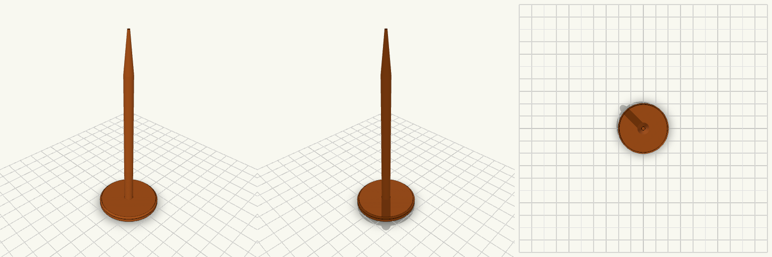
A ground marker nail for holding the position of a robot mower charging station while the charger is stored for the season. It is pushed into the soil where the charger's screw sits in summer. The nail has a wide, flat 40 mm head that stays visible at ground level, a slim 6 mm round shaft, and a tapered point for easy insertion. It prints head-down, so no supports are needed. Head: 40 mm diameter, 4 mm thick, chamfered edge Shaft: 6 mm diameter, about 90 mm long Tip: tapers to a point over 25 mm Overall length: about 119 mm Prints without supports
Perilla de estufa de repuesto con vástago reforzado
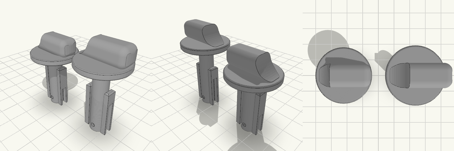
La perilla de la estufa que gira en falso o se parte deja el fuego sin control; esta perilla de repuesto se calza sobre el caño de gas y se traba con pasador, con el pulgar recortado al contorno del collar y todos los bordes del agarre redondeados para girar sin engancharse. La placa trae dos perillas: la original y una copia con vástago de 35 mm para cambiar el largo según la estufa. Cotas que deciden el calce Dos perillas en la misma placa: la original mide 41,5 mm de alto total (12 mm de cabeza + 29,5 mm de vástago); la copia mide 47 mm de alto total (12 mm de cabeza + 35 mm de vástago). En la placa ocupan 58 × 26 × 47 mm. Vástago: 8 mm de diámetro exterior, con dos aletas planas de refuerzo de 24 mm a los lados; en la copia, las aletas quedan en la zona de la punta. Vástago hueco: orificio de 5,5 mm de diámetro, abierto en la punta. En la original llega a 26 mm de profundidad y queda ciego en los últimos 3,5 mm hacia la cabeza, con paredes de aproximadamente 1,25 mm; la copia mantiene el mismo orificio de 5,5 mm. Agujero pasante: 2,2 mm de diámetro, horizontal, con el centro a 3,5 mm del extremo inferior; cruza la cavidad del vástago, así que la chaveta atraviesa el caño de gas. Endija: 3 mm de ancho, abierta en la punta; va a 90° del agujero del pasador, atraviesa el vástago y corta también las aletas laterales, dejando el extremo dividido en dos mitades flexibles. En la original llega a 11 mm; en la copia llega a 17,5 mm, la mitad de su vástago. Cabeza: collar de 26 mm de diámetro por 3 mm de alto; el pulgar mide 26 mm de ancho, 10 mm de grosor y 9 mm de alto sobre el collar, ya no pasa el contorno del collar, es plano de un lado y baja curvo del otro. Todas las aristas del pulgar tienen 3 mm de radio; los bordes del collar tienen 0,8 mm. Cada perilla se imprime de una sola pieza; la endija no separa el modelo, solo deja flexibles las dos mitades del extremo. El acabado negro mate sale del filamento que elijas, no de la geometría. Antes de imprimir, mide el diámetro del caño de gas y el del pasador: el hueco del vástago y el agujero pasante son las dos cotas que no perdonan, y si no coinciden es mejor ajustarlas antes de gastar material.
Beam Clamp Clothes Hanger with Side Hook
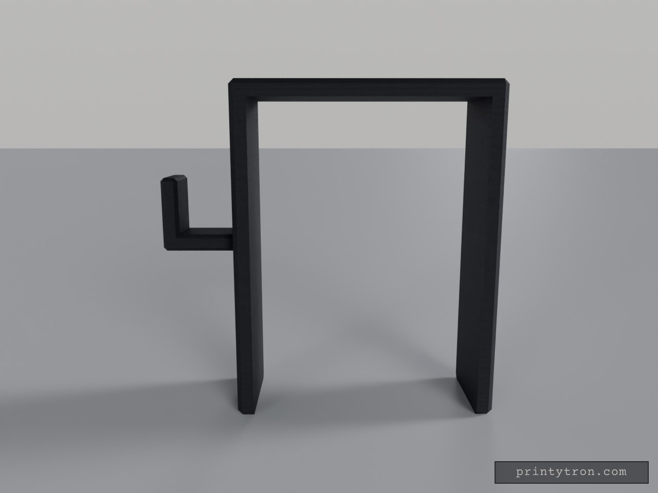
What it's for A saddle that drops over the top of a support beam and turns it into a place to hang clothes. The inverted U-shaped channel grips the beam from above, and a hook projects from one side with an upturned tip so hangers and garments stay put. Beam Saddle — the U-shaped body that slides down over the beam Hook — the side arm with an upward tip for hangers or coats, set at mid-height of the saddle Both areas print as a single piece; nothing needs assembling. Dimensions Saddle opening: 68 mm inner width, sized for a beam of that width Overall saddle: 78 × 30 mm footprint, 100 mm tall Channel: 95 mm deep, with 5 mm thick walls Hook: 22 × 15 × 22 mm, mounted at mid-height so its tip stays inside the 100 mm envelope The 95 mm channel is generous for a shallow beam — the saddle simply sits lower on it, and the hook rides down with it. Print notes Print the saddle opening facing up so the channel needs no supports A few extra perimeters on the hook help when it carries heavy coats Scale the opening slightly if your beam measures over 68 mm Remix ideas Lengthen the hook for bulky winter coats Shorten the legs for a shallower beam and keep the height with a taller top plate Add a second hook on the opposite side for more hanging room Add a small lip or screw hole at the bottom of the saddle to stop it shifting sideways
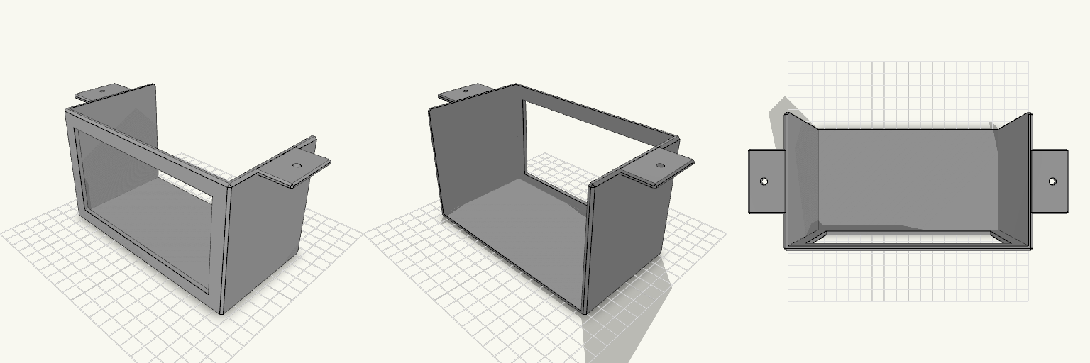
Unterbauhalterung für Echo Show 5 mit offener Rückseite
Die Halterung ist eine Schale für den Echo Show 5, die unter einen Schrank geschraubt wird. Die Rückseite bleibt offen, sodass das Kabel austreten kann; vorn sitzt ein Ausschnitt für das Display. Zwei seitliche Laschen mit je einem 4,5-mm-Loch nehmen die Befestigungsschrauben auf. Die Innenmaße liegen bei 148,6 mm Breite und 90 mm Höhe – bei 148 mm Gerätebreite bleibt so rund 0,3 mm Spiel je Seite. Im Ganzen misst die Halterung 198,6 × 86 × 93 mm, wobei die 86 mm Tiefe den Platzbedarf unter dem Schrank bestimmen. Der Rahmen um das Display ist oben und unten gleich breit: Der obere Rand misst 11 mm (3 mm Boden plus 8 mm Steg), genau wie der untere; der Display-Ausschnitt ist entsprechend oben 5 mm niedriger gehalten. Die Maße sind am Gerät nicht nachgemessen – vor dem Druck die Innenmaße am eigenen Echo Show 5 prüfen. Remix-Hooks Innenbreite: 148,6 mm bei 148 mm Gerätebreite ist bewusst eng gewählt; wer mehr Luft zum Einlegen will, geht auf 150 mm zurück und erhält etwa 1 mm Spiel je Seite. Innenhöhe: 90 mm sind der zweite echte Freiheitsgrad – mehr Höhe schützt das Gerät besser, weniger macht die Schale flacher unter dem Schrank. Tiefe: Die 86 mm Gesamttiefe (rund 80 mm innen) sind die knappste Stelle; eine flachere Schale passt unter niedrige Schrankböden. Displayausschnitt: Der obere Rand ist auf 11 mm gesetzt und entspricht dem unteren; wer mehr Sichtfläche will, kann den oberen Rand schmaler machen, muss dann aber die Rahmenstabilität prüfen. Schraublaschen: Die 4,5-mm-Löcher und ihr Abstand passen sich vorhandenen Schrauben oder einer Bohrschablone an; sie wandern mit der Höhe nach oben mit. Kabelauslass: Die offene Rückseite kann breiter werden oder eine zusätzliche Kabelklemme bekommen. Befestigung: Statt der Laschen ist eine Variante mit Klebefläche oder Klemme denkbar. Als Basis passt die Halterung unter Küchen- oder Regalschränke; Kabelclips und passende Holzschrauben ergänzen sie.
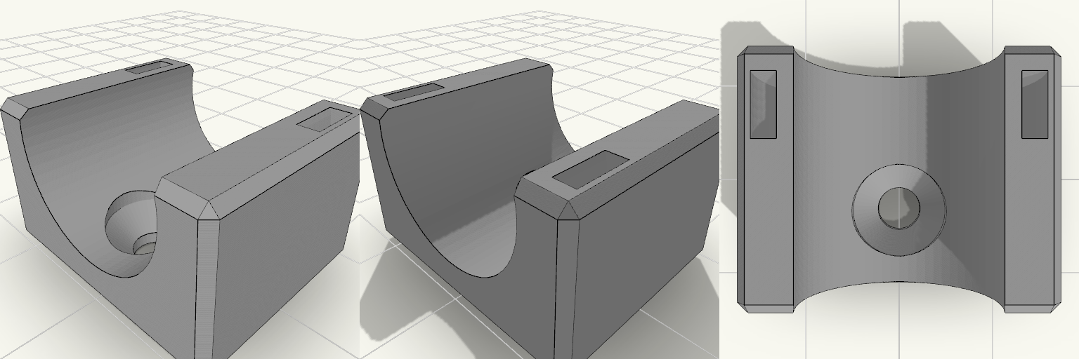
Industrial Saddle Wall-Mount Air-Hose Clip
A plain block with a channel across its top and a single hole sunk into the floor of that channel — drive a drywall screw through it, drop the 5/8″ OD air hose in, and the fixing disappears beneath the hose. A slot cuts through the other half of the block, so a zip tie loops down over the hose and cinches it without ever crossing the screw. No side tabs, no bracket ears, nothing protruding past the saddle: a small, purely functional piece of wall hardware with a squared-off, industrial silhouette. Design notes Top channel sized for 5/8″ OD air hose, with a little clearance. Countersunk screw hole sits in the channel floor with a 9 mm countersink, wide enough for a typical drywall screw head and hidden once the hose is seated. Zip tie slot is offset to the far half of the block, clear of the screw area; takes a common tie up to about 5 mm wide. Load order matters: drive the screw first, then lay the hose in and tension the tie. With a single fastener the block can spin before the hose is loaded — snug the screw down before fitting the hose so it stays square to the wall. Block is 20 mm long, 24.3 × 20 × 14.1 mm overall as it sits on the build plate. Prints as a single body; screws and zip ties are separate hardware.