Round to Rectangular Duct Adapter
Created 3 months ago
Description
A heavy-duty transition duct adapter for shifting airflow smoothly from a round inlet to a rectangular port. Designed with a continuous linear loft and constant 3mm wall thickness to minimize turbulence.
- Round inlet: 250 mm inner diameter
- Rectangular outlet: 300 x 220 mm inner dimensions
- Total height: 200 mm (including 30 mm attachment collars on each end)
- Wall thickness: 3 mm
Photos
Technical views
More like this
Explore more in Workshop & Tools →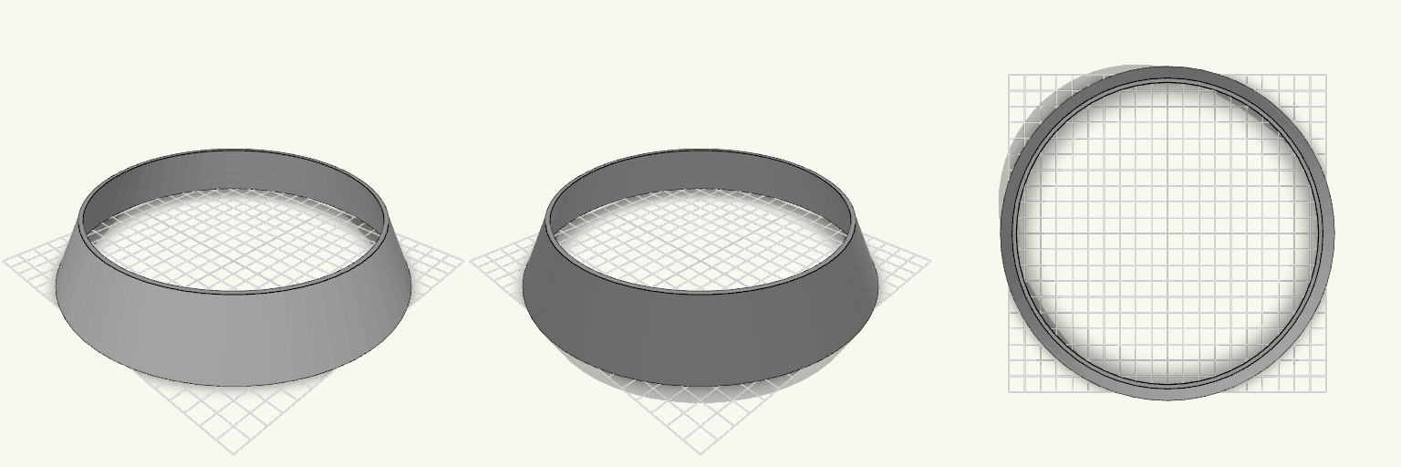
Rough Cone light diffuser
Two round openings that don't share a diameter is the small annoyance that stops everything downstream — the hose won't seat, the liner won't sit, the funnel wobbles instead of funnelling. This is the plain fix: a hollow truncated cone, wide at the bottom and narrow at the top, open at both ends so anything poured or pushed through it passes straight through instead of bottoming out. Fit dimensions Bottom outer diameter: 210 mm Top inner diameter: 170 mm Overall height: 38 mm Wall thickness: 2.4 mm Both ends open — it is a sleeve, not a capped cone Printing It prints as one piece sitting on its 210 mm base, so no assembly and no separate parts to line up afterwards. The wall is thin enough to stay flexible in the hand but still hold its shape, and the shallow flare means the outer surface is not a long unsupported overhang. Check the 170 mm top against whatever has to pass through it before printing — that is the number that decides whether the part works; the 210 mm bottom decides whether it sits down properly.
Placa Rectangular 200 x 50 x 10 mm
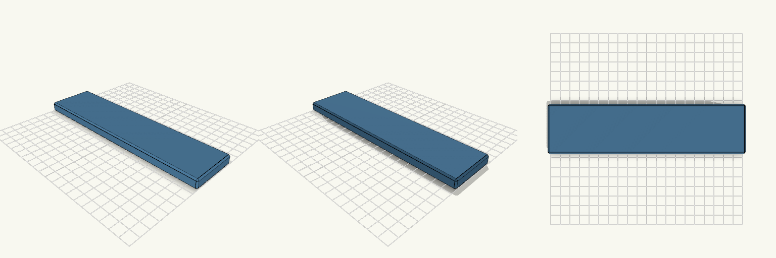
Placa rectangular maciza de 20 cm x 5 cm x 1 cm, para cuando hace falta una base plana y rígida que no se flexione ni se astille en los bordes. Datos para imprimir Medidas: 200 x 50 x 10 mm Bisel de 1,5 mm en todas las aristas, para que la primera capa no se levante en las esquinas Se imprime tumbada sobre su cara más grande, sin soportes Relleno recomendado: 20 % o más, según la carga
cache moteur araignee
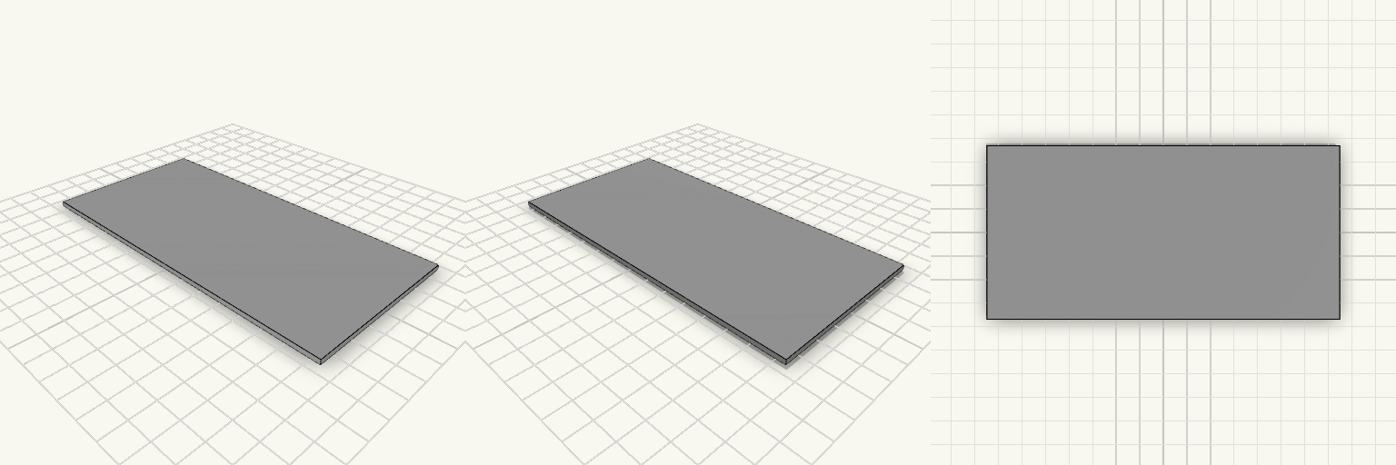
Une plaque plane rectangulaire de 148 × 73 mm pour 2 mm d'épaisseur, posée à plat sur le plateau. Les arêtes sont vives et les faces sont lisses : c'est une base neutre, faite pour être percée, collée, vissée ou redessinée selon le besoin. Elle s'imprime sans support, quelle que soit l'orientation, et sert aussi bien de panneau de fond que de gabarit, de cale ou de renfort. Pistes pour une version à toi Épaisseur (2 mm) : c'est le paramètre le plus utile à faire varier. En dessous, la plaque devient souple et se déforme ; au-dessus de 3 mm, elle devient rigide mais consomme vite de la matière. Garde 2 mm si tu veux une plaque qui se découpe aux ciseaux après impression. Empreinte (148 × 73 mm) : les deux cotes sont libres. La diagonale vaut environ 165 mm, donc la plaque tient dans la plupart des plateaux sans dépasser. Arêtes vives : un congé de 1 à 3 mm sur les quatre coins change complètement le rendu et évite les angles qui s'ébrèchent. Un chanfrein sur le pourtour donne un bord plus doux au toucher. Perçages et découpes : trous de fixation aux quatre coins, rainure centrale, fenêtre traversante — tout se rajoute sans toucher au contour. Ce avec quoi elle s'associe Une plaque comme celle-ci se superpose : deux exemplaires collés font une cale de 4 mm, un exemplaire vissé sur un caisson fait un fond ou une porte, et un exemplaire percé devient un gabarit de perçage. Si tu la destines à un objet précis, indique les cotes de cet objet plutôt que de repartir de zéro : c'est la seule mesure qui compte vraiment.
SpoolScope — Filament Remaining Gauge
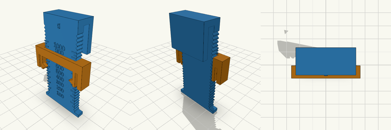
SpoolScope is a two-part gauge for estimating how much filament remains on a standard spool, made for spools that sit out of easy view in an AMS or on a shelf. The rail hooks over the flange rim; the sliding block rides on it with light detents, so you can push it down until it touches the filament, lift the gauge away and read the result. Raised ticks and numbers plus an unambiguous arrow on the block make the measurement clear without needing line-of-sight while the gauge is in place. Features Two printed parts: a rail with a rim hook, and a detented sliding block. Gram scale from 0 to 1000 g, with ticks every 50 g and numbers every 100 g. Ticks follow filament geometry rather than an even spacing: closer together near full, wider apart near empty. Arrows on the block tip directly toward the scale, and the detents hold the reading after the gauge is lifted off. Hook gap of 4 mm, sized to clear flanges from 2.8 mm to 3.6 mm thick. Dimensions Flange diameter: 200 mm. Hub outer diameter: 95 mm (from a measured Polymaker spool). Full-roll diameter: 170 mm (estimated from a 1 kg PLA roll on a 95 mm hub and a 65.6 mm spool width). Hook gap: 4 mm. Fitting and calibration Sized around Polymaker and Inland 1 kg spools; other brands are worth checking against the hub and flange figures above. The scale can be shifted by a single fixed offset if a first print reads consistently high or low, so a weight check against a known spool is worth doing before trusting the numbers. If the error differs between a full and an empty spool, the hub and full-roll values are the ones to correct. Print notes Both parts are laid out flat on the print plate. The block contacts the filament at its outer edges rather than at the centre, so a reading can sit slightly high; a weight check against a known spool is the best way to confirm the scale.
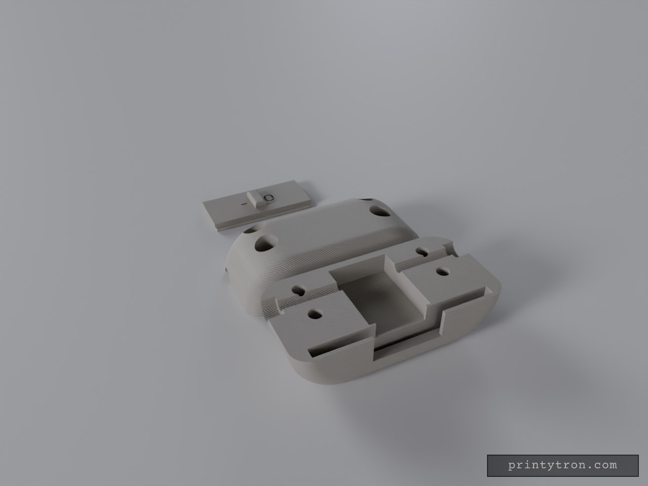
Oval Electrical Switch Housing with Slider
A pebble-shaped housing for a small electrical switch, built as two lengthwise half-ovals plus a separate sliding cover. The front and back halves split along the wire axis, and the seam runs through the middle of both 3 mm wire holes and the switch pocket. Lay the switch and wiring into one half, drop the sliding cover into the half-cut T-track, then close the other half over it like a clamshell. Four M3 screws pass through the back half and thread into M3 nuts seated in the front half from outside, so the seam clamps evenly and the two halves of the track stay aligned instead of catching the cover on a step. The housing is 54 × 27 mm in plan and 26.4 mm tall, with an 8 mm rounding on the bottom edge and 4.5 mm on the top so it reads as a pebble rather than a puck. Inside, the pocket is 15.9 × 11 × 20.2 mm — a 15.3 × 10.4 × 19.8 mm switch plus about 0.5 mm clearance per side. The sliding cover is 32 × 16.4 × 4 mm including its thumb tab and fills the full track width, travelling 14 mm. Its top is closed and trimmed to the housing's oval outline, so the outside reads as one continuous curved form; the 13.1 × 8.2 mm window is a blind recess on the underside with about 1 mm of skin above it. Slide the cover toward +X until the recess lines up with the opening to expose the switch, and back toward −X to close it. A small rectangular thumb tab, 3.6 mm along X and 8.2 mm across, sits at the cover's center and rises about 0.6 mm above the housing surface. Its top edges are rounded at 0.9 mm so it blends into the oval's curve, and its width matches the switch opening. Engraved marks 0.5 mm deep on the cover top indicate state within the exposed middle: "o" sits 4.2 mm on the +X side of the cover center and shows when closed; "-" sits 4.2 mm on the −X side and shows when open. Only one mark is visible at a time because the other slides under the roof. Both wire ports open into a 6 mm round seat, 6 mm long, ready for a wire holder of that size; the channels themselves stay at 3 mm. A roof spans the track from x = ±9 mm out to each end of the oval. It is part of the two housing halves and follows the oval's top curve, covering the track ends so no open slot shows there and closing the small triangular corner gaps. The cover runs under the roof, with its top about 0.2 mm below it; the middle section from x = −9 to +9 mm stays uncovered because the cover needs that clearance to move. The end stops are integrated into the two housing halves: each half carries its share of a stop at both ends of the track, and the stops fill the track's full cross-section, including the wide groove and neck, ending flush with the oval's outer surface. The cover is blocked at both ends of its travel and cannot slide out. To fit or remove the cover, open the halves as you would for the wires and switch. There are no separate loose stops left in the model. Fasteners and seam Four M3 screws, at x = ±17 mm and heights of 5 mm and 14 mm — solid body clear of the switch pocket and the wire channels. Use M3 × 18 mm; M3 × 20 mm also works, but its tip can poke through slightly. Back half (purple): 3.4 mm clearance holes through the wall, with 6.2 mm counterbores so the heads sit 6 mm in from the seam. Front half (blue): 3.4 mm screw holes run from the seam to a flat nut seat 9.8 mm out. The hex pockets are 6.5 mm across the corners and 4.2 mm deep for a standard M3 nut (5.5 mm across the flats). They open through the outer curved surface, so each nut drops in from outside and sits flush. The lower pockets are close to the bottom curve, so check that wall when you print. Print layout The three pieces are arranged side by side on the plate, not overlapping, so each can be exported on its own: Front Half (blue): 54 × 26.4 × 13.5 mm. The current plate keeps it split face up; with no pins on that face it can be flipped to sit split face down and print without supports. Back Half (purple): 54 × 26.4 × 13.5 mm, split face on the bed, so it needs no supports. Sliding Cover (orange): 32 × 16.4 × 4 mm, upright with its flat underside on the bed and the thumb tab on top. The fit has not been tested, so check the slide, the nut pockets and the screw alignment before a long print. Remix hooks Pocket — 15.9 × 11 × 20.2 mm. The first thing to re-cut for your own switch. Hold roughly 0.5 mm clearance per side: tighter grips it, looser lets it rattle. The 15.9 mm runs along X, so keep that orientation if the wires must stay in line with the cover. Split plane — along the wire axis. The seam runs through both 3 mm wire holes and the switch pocket. Moving it off-centre changes how the halves sit and where the wire seats land; keep the four screw holes aligned at x = ±17 mm, heights 5 mm and 14 mm. Screws and nuts — M3, 3.4 mm holes, 6.5 mm external hex pockets. Swap the external hex pockets for heat-set inserts or threaded bosses if you'd rather not handle loose nuts, or step down to M2.5 in the same bosses if 3 mm screws crowd the 27 mm width. Counterbore depth sets how far the heads sit in. Wire seats — 6 mm diameter × 6 mm long, feeding 3 mm channels. Resize these to match your actual wire holder, or turn them into a plain grommet relief if the wiring takes a different route. Sliding cover — 32 × 16.4 × 4 mm. It runs between the integrated stops and carries the blind 13.1 × 8.2 mm recess underneath. Lengthen or shorten the solid and recessed sections to change how far it travels before the switch is exposed; the current travel is 14 mm. Thumb tab — 3.6 × 8.2 mm, about 0.6 mm proud, with 0.9 mm rounded top edges. It must clear the roof ends at x = ±9 mm through the 14 mm travel. Changing its width, its rounding, or the roof span changes that clearance. Roof span — x = ±9 mm to the track ends. This sets how much of the track is covered and how much middle stays open. Raising or lowering the roof changes the cover's clearance and how flush its top sits; widening the exposed middle makes both marks visible at once. Integrated stops. They are cut into both halves at the ends of the track and fill the track cross-section, so changing the cover length means moving them rather than swapping a separate part. Shorten the cover instead if you want to keep the current stop positions. Oval body — 54 × 27 mm in plan, 26.4 mm tall. Stretch the oval along X to fit a deeper switch, and adjust the top and bottom edge roundings to change how soft or blocky it looks. Keep the wire-hole centreline in mind when moving the ends. Layout. Each piece keeps its own print orientation, so you can drop one piece or re-arrange the plate without touching the others. Variants worth trying Replace the "-" and "o" engravings with "OPEN" and "LOCK" lettering, or run a single indicator line across the cover. Add short alignment pegs beside the screws, or a tongue-and-groove along the seam, if the halves don't register well before tightening. Flatten one long side into a mounting tab with a screw hole so the housing can be fixed down. Print the cover in a contrasting colour to one or both halves so the split line and track read clearly.
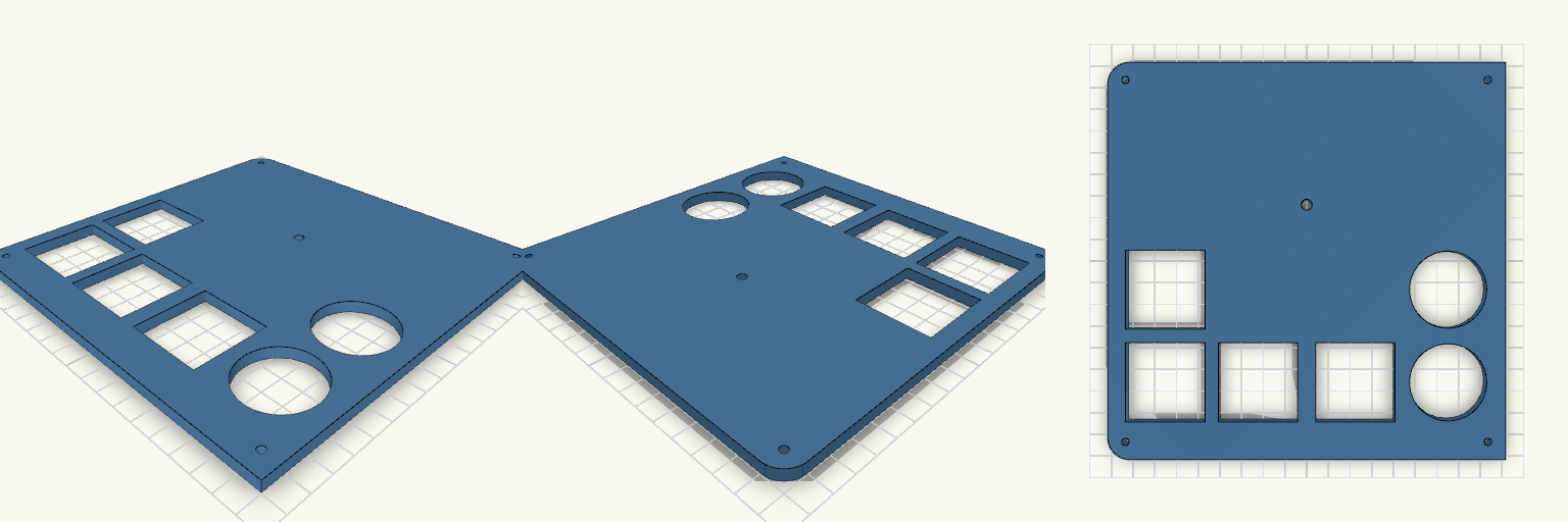
Tapa cuadrada con agujeros mixtos
Tapa de 180×180×5 mm con dos lados redondeados a la izquierda (radio 10 mm), cuatro agujeros M3 en las esquinas y un agujero de 5 mm. Dos agujeros redondos de 35 mm a la derecha y cuatro cuadrados de 36 mm a la izquierda, en la zona inferior. Ideas para remezclar Diámetro de los redondos (35 mm): súbelo o bájalo según la pieza que deba pasar; la pared entre ellos es de 7 mm. Lado cuadrado (36 mm): ajústalo por separado; los centros están a 42 mm. Radio de las esquinas (10 mm): 5 mm para una curva más suave. Agujero de 5 mm: está a 25,5 mm sobre el centro; muévelo para un pasacables o un pulsador. Combina con: una base o caja de 180 mm usando los M3 de las esquinas (3,4 mm, a 8 mm del borde).