Schneekufe für Skateboard, Truck-Lochbild 53 × 41 mm
Created today
Description
Schneekufen für Skateboards, die auf Schnee und Eis gefahren werden. Die Kufe wird über das Truck-Lochbild an der Achsaufnahme verschraubt und sorgt für Führung auf glatten Untergründen. Die Sohle ist 170 mm lang, 50 mm breit und 2 mm dick; der mittlere Steg ist 6 mm dick. Die Sohle ist über die gesamte Länge flach ausgeführt. Montageplatte, Steg und Lochbild sitzen 25 mm zum hinteren, breiten Ende hin versetzt, sodass der Steg voll auf dem flachen Teil der Sohle steht. Das vordere Ende verjüngt sich geradlinig zu einer etwa 10 mm breiten, leicht gerundeten Spitze; das gegenüberliegende Ende bleibt breit. Beide Sohlenenden haben eine 3-mm-Fase. Für ein Skateboard sind zwei Kufen nötig.
Maße und Montage
- Gesamtmaß: 170 mm lang, 50 mm breit, 33 mm hoch
- Sohle: 2 mm dick, durchgehend flach
- Mittlerer Steg: 6 mm dick, steht voll auf der flachen Sohle
- Verjüngung: geradlinig zur Spitze, Spitzenbreite etwa 10 mm, leicht gerundet
- Gegenüberliegendes Ende: breit ausgeführt
- Enden: 3-mm-Fase an beiden Sohlenrändern
- Befestigungspunkt: Montageplatte mit Truck-Lochbild 53 × 41 mm, 25 mm zum breiten Ende versetzt
- Schraublöcher: 5,4 mm, oben angesenkt
- Befestigung: handelsübliche Schrauben und Muttern
- Die Maße sind Standardwerte und nicht an ein bestimmtes Board angepasst – vor dem Druck mit dem eigenen Truck-Lochbild abgleichen
Druck
- Passt auf das Druckbett eines A1 mini
- Durchgehend flache Sohle: kein Stützmaterial an der Spitze nötig
- 2-mm-Sohle: auf dem A1 mini etwa die Untergrenze; die Sohle wird flexibel und gibt unter Last nach, daher mit mehreren Wandlinien drucken
- Material: PETG oder ASA
- Stückzahl: zwei Kufen pro Skateboard
Images
More like this
Explore more in Automotive, RC & Hobby →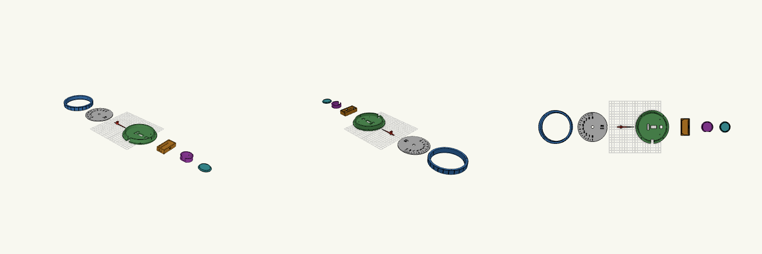
Tacómetro muscle car de 127 mm
Un tablero de estilo muscle car a escala grande: 127 mm de diámetro exterior, con la esfera estriada, el dial negro de números grandes y una aguja fina de punta afilada que evocan los tacómetros AutoMeter de los tableros deportivos. La escala barre de 0 a 9.000 RPM en 180° —de las 6 a las 12 en sentido horario— y la zona roja arranca en 8.000 RPM. Detrás del dial va un servo SG90, así que la aguja se mueve de verdad, y el conjunto no lleva carcasa trasera. El dial mide 113 mm y deja 109 mm de ventana visible: números, marcas y zona roja escalan con el aro para que la aguja llegue a las marcas. El conjunto se imprime en siete piezas separadas y sin soportes: Aro frontal: 127 mm de diámetro, labio de 2 mm, estrías exteriores y cuatro agujeros para tornillos M3. Lleva una llave de orientación para el dial y dos agujeros piloto a las 12, a ±6 mm del centro, para la luz flash de corte de RPM. Dial: disco de 113 mm con los números 0–9 y los textos «RPM» y «x1000» pasantes de lado a lado —con puentes finos de 0,8 mm que sostienen las islas interiores—, marcas cada 500 RPM y zona roja en relieve. El agujero central es de 10 mm más 0,3 mm de juego de encastre. Aguja: perfil fino de aguja real, con puntero de 50 mm que se angosta desde 1,2 mm hasta unos 0,6 mm en la punta y una cola de contrapeso corta; el cubo central es de 10 mm para dejar el dial despejado. Se monta en el brazo del servo recortado a 12 mm de radio y se fija solo con el tornillo central de 3,2 mm, sin pasador. Soporte servo: placa de 4 mm con ventana para el SG90, dos agujeros piloto para la brida, muesca de llave y ventana de 12 × 12 mm para el cable del servo. Se fija al aro con cuatro tornillos M3 y recibe la caja de ESP32 con dos tornillos M3 desde adelante, con los agujeros a ±29 mm. La ventana del servo mantiene las medidas compactas del SG90. Caja ESP32: pieza aparte de 31 × 65 × 16 mm para una placa de 30 pines de unos 51 × 26 mm, con ranura para el USB, dos rieles internos que sostienen la placa y salida de cable hacia el soporte; se adosa al soporte del servo y queda por detrás. Caja de LEDs: cilindro de 41 mm de diámetro y 14,8 mm de alto, con paredes y fondo de 2 mm y cámara abierta hacia el frente. Va a las 12, con el borde curvado apoyado en el aro, y se fija con dos tornillos M3 horizontales a ±6 mm del centro; la salida del cable de la tira LED está en la pared trasera. Quedan unos 37 mm libres en el interior, suficientes para un LED o un tramo corto de tira. Tapa difusora: disco de 41 mm con solo 1,2 mm de piel, con un anillo guía que entra con 0,3 mm de juego. Es fina para que pase la luz y se imprime con la cara exterior hacia abajo; puede imprimirse en el color del flash —rojo, azul o blanco— en PLA translúcido o natural. Notas de armado y acabado: Los números pasantes dejan pasar la luz de atrás: se puede colocar un filtro de otro color detrás del dial y cambiar el tono de la iluminación. Los puentes se ven como una línea fina en medio de cada número: un puente vertical en el 0 y el 8, uno horizontal en el 4, el 6 y el 9, y otro horizontal sosteniendo la R, la P y los ceros de «RPM x1000». Es lo normal en un estilo stencil. El centro de 10 mm deja paredes de unos 0,9 mm en el cubo de la aguja; conviene imprimir esa zona con 100 % de relleno. Las marcas y la zona roja van en relieve en el mismo archivo que el disco: para cambiar su color hay que pausar la impresión en el cambio de capa. La tira LED no tiene soporte interno: se pega con su adhesivo en la pared interior de la caja de LEDs. Al montar, alineá el brazo del servo en 0° apuntando a las 6 y comprobá la altura del brazo sobre la brida en tu SG90 antes de cerrar el conjunto.
Bay windows for shops
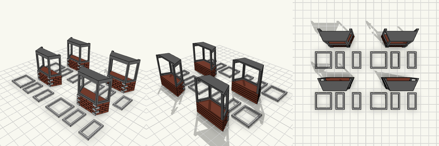
OO scale bay window body, 36 mm wide, 13 mm deep and 40 mm high, with 13 mm of brickwork at the base and three window openings above. Three open window frames print separately on the plate for painting and gluing into the openings. Scale: OO gauge (4 mm to 1 ft) Overall size: 36 × 13 × 40 mm Brickwork: 13 mm high, horizontal courses with staggered joints Front window: 24 mm wide opening; two angled side windows about 14.3 mm wide Frames: 1.6 mm thick with 1.6 mm borders and a through-opening Fit: frames sized with clearance to their openings Back: open, for gluing to a wall
Mountain Bike Wagon Hitch with Capped Post
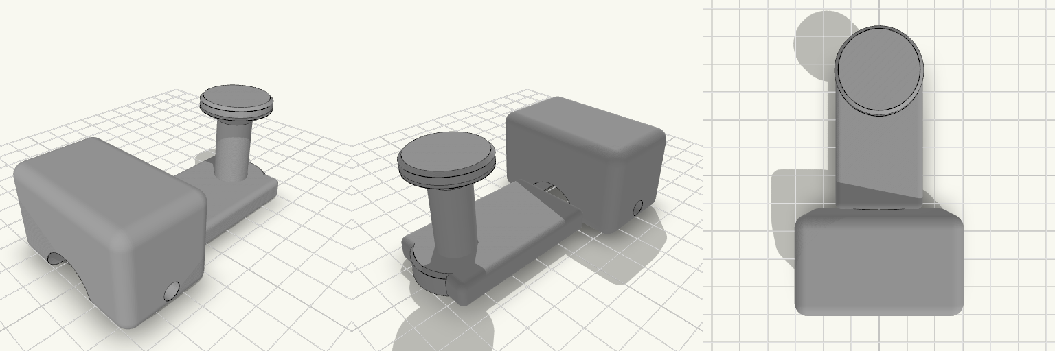
What it's for A hitch that lets a mountain bike pull a wagon by its C-shaped handle. The bike side is a clamp block that grips the frame tube with a pinch bolt; a flat arm carries that back to an upright post. The post ends in a 12 mm neck with a flared cap on top, so the wagon's C-handle drops over it and cannot slide off while you ride. Clamp block with a 22 mm bore and a single pinch bolt — check this bore against your actual seat stay or axle tube before printing, and scale the clamp if your tube differs Flat arm sets the post behind the clamp, clear of the frame Capped neck holds the handle on but still lifts off when you want to unhitch Dimensions Overall footprint on the plate: 50 × 83 × 38 mm Clamp bore: 22 mm Post neck: 12 mm diameter, about 22 mm tall, with a flared cap above it Print notes Print the part as oriented on the plate so the clamp bore and the neck stay round and the arm keeps its strength across the layer lines. A tough filament such as PETG or ABS/ASA suits a part that takes trail vibration and towing loads better than plain PLA. Remix ideas Resize the clamp bore for thinner or thicker frame tubes, or split the clamp into a two-bolt version for rougher trails Lengthen the arm to move the post further back for wider cargo or tighter frame clearance Swap the capped neck for a ball or pin joint if you want the wagon handle to pivot more freely
final version 25 mm Paddle Shaft
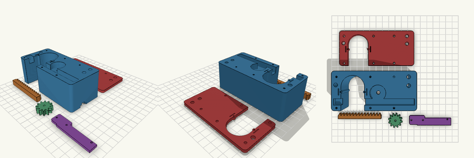
Motorised rack-and-pinion U-holder for a 30 mm paddle shaft, with hollow flexing snap detents on the slot walls. Fit Host: 30 mm round paddle shaft in a 32 mm slot; N20 gear motor, 12 × 10 mm body, 3 mm shaft. Detents: each slot wall has a hollow bump (1 mm radius through-hole) on a flex finger with a relief slit. The cover plate carries the same features. Not for: shafts other than about 30 mm, or motors with a different body size. Check before printing Measure the N20 body length including gearbox and terminals; the motor length is a parameter. Detent stiffness depends on the bump height and the hole radius. Adjust them for your filament. Parts Housing, sliding rack, pinion, motor retainer and cable cover (one piece), guide cover plate.
iPhone 15 Pro Bike Mount 31.8mm Bar
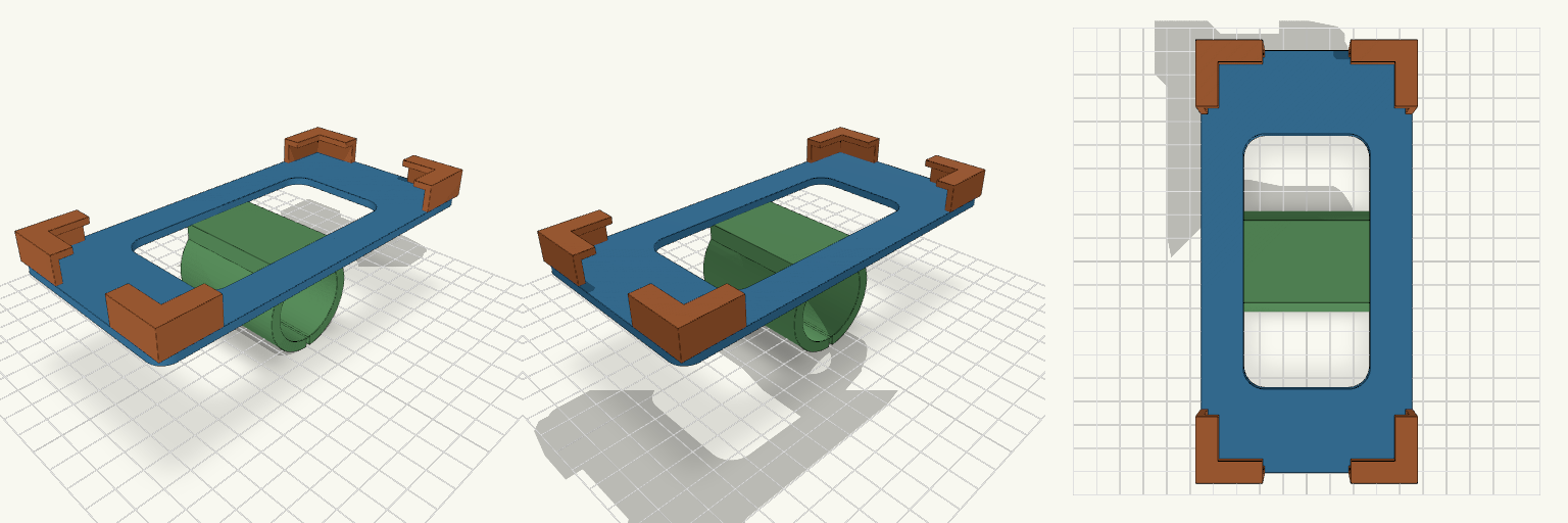
Handlebar phone mount sized for the iPhone 15 Pro (146.6 × 70.6 × 8.25 mm). A back plate with a weight-saving window holds the phone, four L-shaped corner clips wrap the edges and hook 4 mm over the screen face, and a split clamp on the back fits 31.8 mm handlebars. The clamp split is present, but no bolt tab or hardware mounting is included yet. A strap or added bolt tab is needed to tighten it on the bar. Specifications Phone: iPhone 15 Pro, 146.6 mm tall, 70.6 mm wide, 8.25 mm thick Pocket: 71.2 × 147.2 mm inside (0.6 mm total clearance) Corner clips: 4, each with 18 mm arms along both edges, 2.4 mm wall, 4 mm lip over the face Back plate: 3 mm thick, 6 mm corner radius, central cutout to reduce weight Clamp: 31.8 mm bore, 4 mm wall, 50 mm wide, split at the bottom Overall size: 76 × 152 mm footprint, about 54 mm tall in the print orientation Print notes: supports needed under the back plate in the modelled orientation; PETG or ASA suggested for heat and vibration Parts: back plate, corner clips, handlebar clamp (single welded body)
Six Kayak Trailer with Jockey Wheel
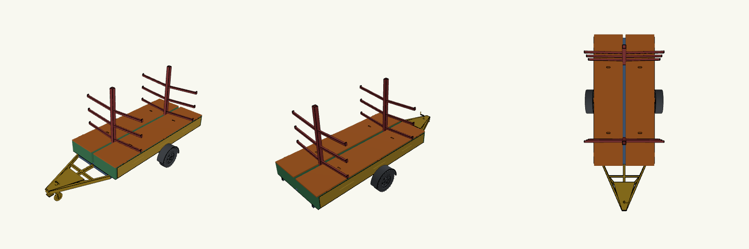
A trailer for carrying six kayaks, three per side, on two centre columns with branching support arms. Full-length lockers run along both sides under the kayaks, each with a side door for paddles and life jackets. The A-frame drawbar carries a ball coupler with latch, lever and safety chain, plus a jockey wheel with a tyre, rim, fork and a crank handle on top. Six kayak positions, three per side Two full-length side lockers with side doors Twin wheels with tyres, rims and mudguards A-frame drawbar with cross members, spine and braces Jockey wheel with top crank handle