Solid Back iPhone 13 Case
Made by NickelEgret
Created 1 months ago
Description
A custom-fit TPU or rigid shell for the iPhone 13 that prevents the phone from slipping or taking raw impacts on the edges. The back is a solid panel for maximum protection.
The button zones feature wide windows rather than thin button-covers, exposing the actual hardware so you get the real tactile click of the buttons without fighting the case material.
Print Notes
- Fit Tolerance: Exact to the iPhone 13 body (71.5 mm x 146.7 mm).
- Material: TPU is highly recommended to let the lip flex over the screen edge. Rigid filaments like PETG will be a very tight snap-fit.
Images
More like this
Explore more in Desk & Tech →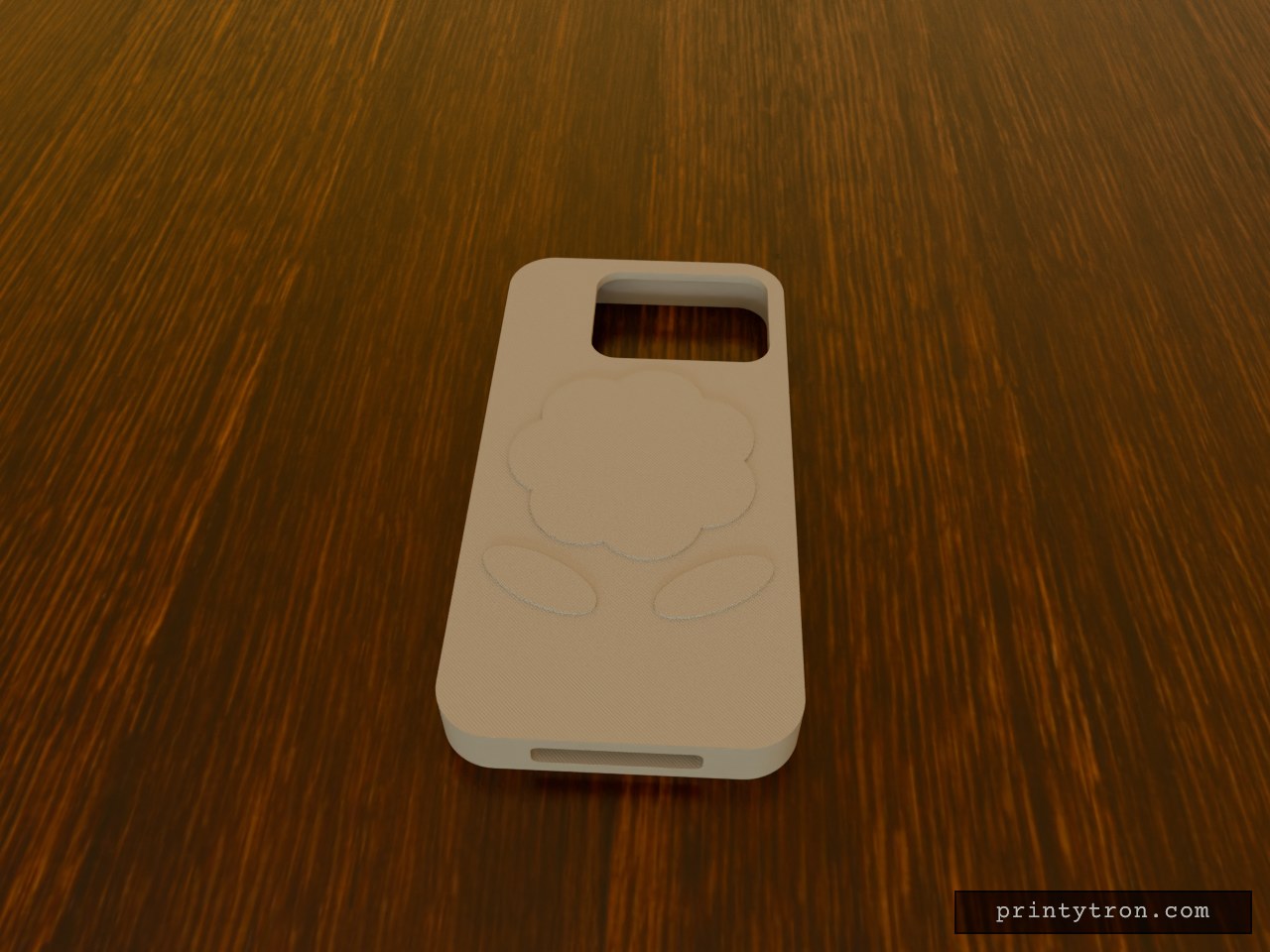
iPhone 17 Pro Max Case, Blue with Rose
What it's for A protective case for the iPhone 17 Pro Max in light blue, with a raised rose on the back below the camera cutout. Dimensions Phone body: 163.4 × 78 × 8.75 mm, with 0.3 mm of play per side Walls 4 mm, back 3 mm Rose relief: 1 mm, flat-topped layers Remix ideas Recolour the rose in blue tones to blend with the case Make the rose taller or soften its edges Swap the rose for another motif
4" LCD Click-In Bezel, 4 mm Tall
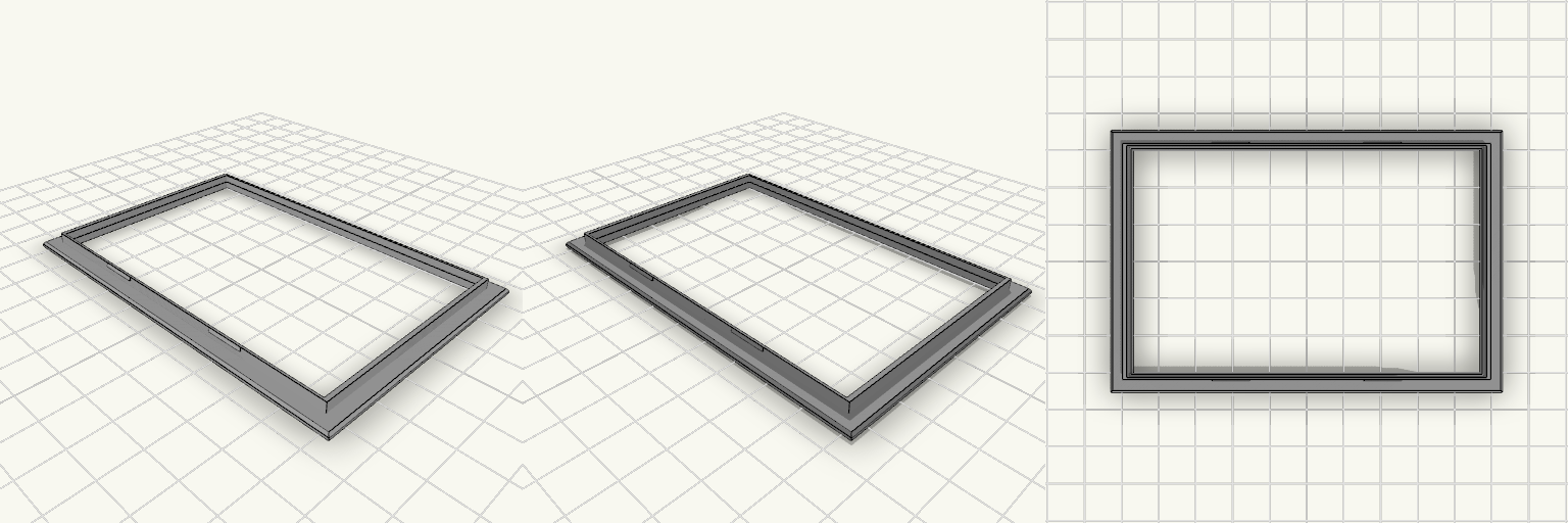
A click-in bezel for a 4" LCD touch display mounted in a 97 x 62.2 mm panel window. The 4 mm overall height keeps it low, and a front flange hides the window edge while the screen sits in a pocket behind it. Remix hooks Screen overlap: the visible opening is 93.5 x 60 mm, so it covers 0.5 mm of the 94.5 x 61 mm screen per side. Change the overlap value to show more or less of the screen. Flange: 1.2 mm thick, 105 x 70.2 mm, with a 0.6 mm top chamfer. Widen it to hide a sloppier window cut. Body and clearance: 96.7 x 61.9 mm, 0.15 mm clearance per side. Raise to 0.2 to 0.3 mm for looser printers. Snap barbs: four, 10 mm wide and 0.4 mm proud, tuned for a 2 mm panel. Move them or change their height for other panel thicknesses. Pocket depth: about 2 mm. Deeper pockets need more overall height. Pairs well with a printed rear cover or a spacer plate if the panel is thicker.
Wireless Earbud Case Charging Dock
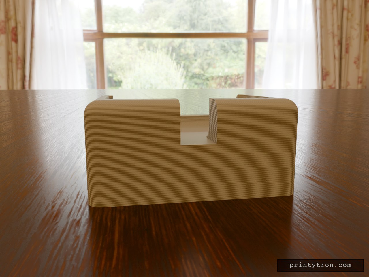
An upright charging dock for a wireless earbud case, sized for a desk. The case sits in a 50 × 30 mm pocket, 12 mm deep, on a 60 × 45 × 28 mm base with rounded corners and a flat bottom. A 10 mm notch at the back of the pocket routes a charging cable to the case, and a 4 mm front lip above the pocket floor keeps the case from sliding forward. It replaces a loose case sliding around the desk with a fixed upright position. Fit check Fits: wireless earbud cases with a footprint no larger than 50 × 30 mm and a charging port that faces the rear notch. Does not fit: cases wider than 50 mm or deeper than 30 mm; cases with a bottom-only charging port, because the pocket floor is solid and the notch opens only at the back. Check before printing: measure your earbud case footprint and confirm the 10 mm rear notch lines up with the charging port and plug. Print: one connected piece with a flat bottom and rounded edges, designed for reliable FDM printing on an older printer. No separate pieces or assembly.
Funda Galaxy A20e pablo
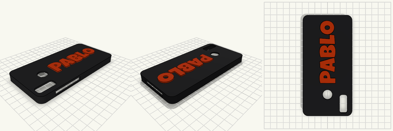
Funda rígida diseñada específicamente para las dimensiones del Samsung Galaxy A20e (147,4 × 69,5 × 8,3 mm), incorporando márgenes de tolerancia estructurales para facilitar la inserción del dispositivo. La cara trasera presenta el nombre "Pablo" integrado en relieve volumétrico sólido, utilizando la fuente seleccionada para maximizar la resistencia de las letras. Material recomendado: PLA, PETG o TPU (dependiendo de la flexibilidad deseada). Relieve de texto: 1,5 mm, extruido hacia el exterior. Tolerancias: +0,6 mm en ejes X e Y para un acople por fricción sin forzar la estructura. Perforaciones: Cámara principal dual, lector de huellas dactilares trasero, botonera lateral completa y acceso inferior (USB-C/Audio/Altavoz).
Mini-Server-Box with Feet, Lid and Fan
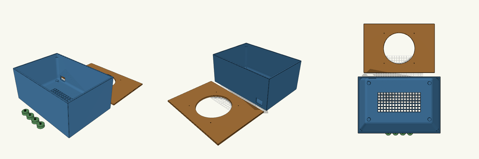
What it's for A solid-walled enclosure for hiding and cooling equipment. Every side wall is closed, and the only airflow path is a sturdy grid cut into the floor, so the box stays dark and quiet from the sides. A 30 × 20 mm cable hole in the lower rear corner lets wiring in and out, and the flat lid lifts off for access. The model prints as separate pieces: the box, the lid and four feet. The lid is a flat plate with a locating lip underneath, slightly larger than the box on every side so it overhangs and can never drop inside. Each foot carries its own coarse threaded stud, so the feet screw directly into matching threaded holes in the floor bosses with no separate fasteners. Dimensions Box: 290 × 200 × 130 mm, with 4 mm walls, solid on all four sides, an 8 mm floor, and a 50 mm solid border around the floor grid. The floor grid is centred on the narrower floor. The thicker floor makes the mesh bars deeper, so airflow per opening drops slightly. Inside fillets: 10 mm radius on the vertical corners and the floor-to-wall edges, stopping 15 mm below the rim. The top 15 mm stays square so the lid and its lip fit without changes. Lid: 294 × 204 mm, 9 mm overall with a 5 mm plate and underside lip; overhangs the box by 2 mm on all sides; 140 mm fan opening and four 3 mm fan screw holes at 124.5 mm center-to-center. Cable hole: 30 × 20 mm in the rear wall, set 20 mm from the left edge and 12 mm above the bottom, inside the solid section so it doesn't weaken the corners. Feet: four solid 24 mm discs, 10 mm tall, each with a 6 mm thick, 8 mm long threaded stud on top; 18 mm overall. The studs use a 1.5 mm pitch. Foot sockets: four corner bosses widened to 14 mm, with threaded holes 6.6 mm across and 11 mm deep at the same 1.5 mm pitch, giving about 0.6 mm clearance on diameter. Print notes Print the box, lid and feet separately. Print the lid lip-side up so its flat face sits on the bed and the lip rises clear of the plate. The floor grid benefits from enough perimeters to keep the bars sturdy. The threads have not been test-fitted; if the feet bind, raise the socket diameter slightly, and if they wobble, lower it. Test-fit the fan and check its screw-hole spacing before committing to a full print. Remix ideas Add a removable filter frame behind the fan opening. Add internal standoffs or a shallow tray for mounting equipment inside. Resize or duplicate the rear cable port for thicker cable bundles. Swap the floor grid for a denser or more open pattern to change the airflow.
Four-Board 1U Rack Mount for Orange Pi 5 Pro
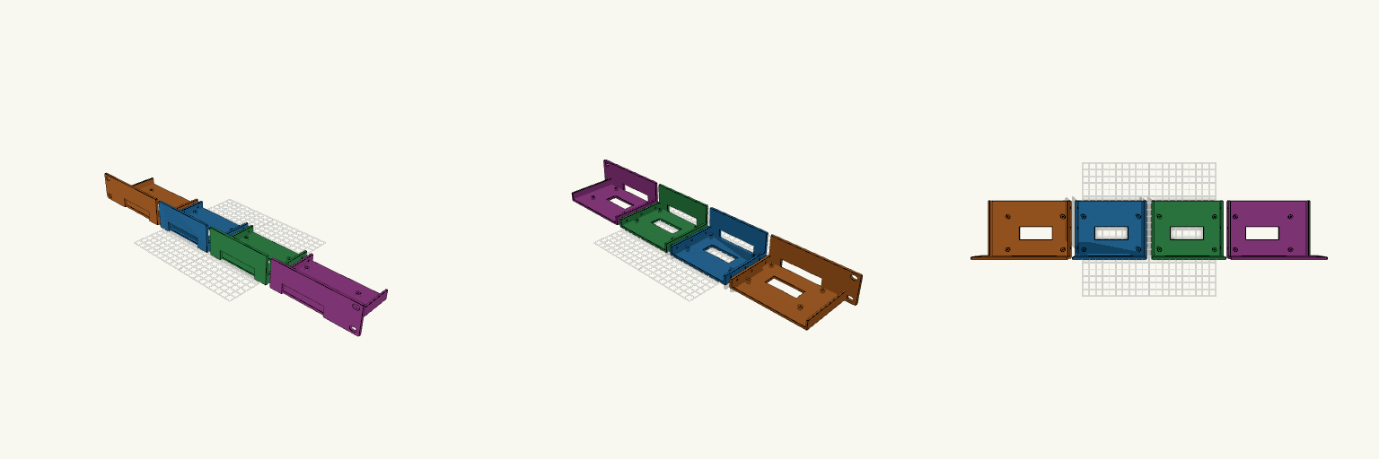
A 1U, 19-inch rack mount that holds four Orange Pi 5 Pro boards side by side. The front panel fills a standard rack opening and the tray behind it carries the boards at 105 mm spacing, so all four sit behind a single 1U slot. Slotted ear holes line up with standard 19-inch rack spacing, and four 66 × 16 mm cutouts in the panel line up with the boards for power and Ethernet cables. The mount is split into four modules that print separately and bolt together, so it fits beds of roughly 150 mm or larger. Print each module flat on its back with the tray side down. Every seam has a rib with three 3.4 mm holes for M3 bolts; cut through the rib and those holes become the clamping points between neighbouring modules. Cutouts and standoff positions are based on an assumed board footprint of about 89 × 56 mm, so check them against your boards before printing. Ear modules: 136.3 × 85 × 44.5 mm each Centre modules: 105 × 85 × 44.5 mm each Seams: centre and ±105 mm, three M3 bolt holes per seam Board spacing: 105 mm between positions Cable cutouts: four at 66 × 16 mm Standoffs: four per board, 2.2 mm pilot holes Panel height: 44.5 mm (1U), ears slotted at standard rack spacing