Universal Dust Bag Dock Adapter
Created 2 months ago
Description
A parametric conversion plate designed to adapt universal slide-in dust bags to a specific vacuum auto-empty dock.
The model provides a baseline structure with a central suction tube for the dock interface and C-channel rails on the reverse side to capture the cardboard collar of a generic bag.
Design Notes
- Parametric setup: The code exposes variables for the dock plate footprint, suction tube diameters, and the universal bag's collar dimensions.
- Orientation: Built with the dock interface on one side and the bag rails on the other. You will need supports under the central tube if printed with the rails facing up.
- Tolerances: The default rails leave a standard 0.5mm clearance for a typical 3mm cardboard collar.
Photos
Technical views
More like this
Explore more in Home & Fixtures →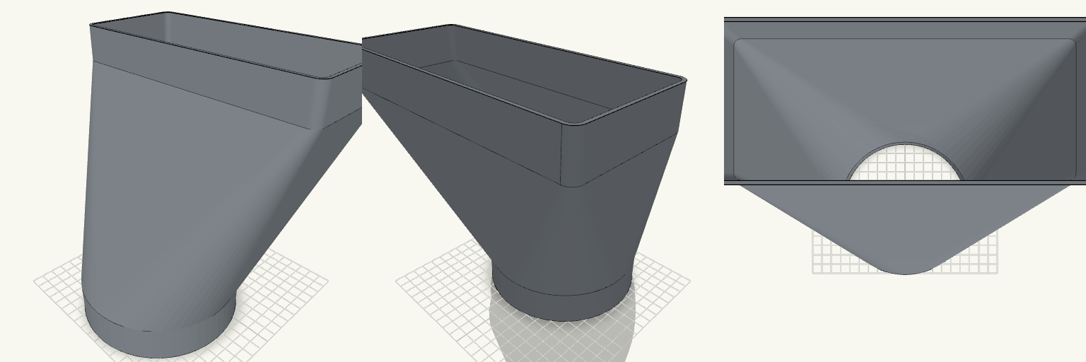
Eccentric Duct Adapter 125mm
What it's for Bathroom duct adapter that joins a round duct to a flat rectangular duct in one continuous piece. Both ends are female sockets, so the ducts slide into the adapter rather than over it, and the internal passage stays fully open from end to end with no obstruction to airflow. The round socket is bored to Ø132 mm for a free, loose fit over Ø125 mm duct — roughly 3.5 mm of clearance per side, which can be taken up with tape or a gasket if a tighter seal is wanted. Dimensions Round socket: Ø132 mm inner, Ø136.8 mm outer, 30 mm long, 1.5 mm entry chamfer Flat socket: 222 × 92 mm inner, 5 mm corner radius, 30 mm long Transition: 160 mm, smooth round-to-rectangle loft, horizontally symmetric Vertical offset of the flat socket: 72.5 mm Wall thickness: 2.4 mm throughout Overall length: 220 mm Print notes Print as one piece; no assembly and no supports are needed for the open bore. The bounding volume on the plate is about 227 × 189 × 220 mm, so check the build volume before slicing. A 2.4 mm wall prints cleanly in PETG or ABS if the part sees warm bathroom air; PLA works for a dry run-in fit. Remix ideas Change the bore diameter to tune the fit for a different round duct. Adjust the 72.5 mm vertical offset for another mounting position. Lengthen either socket for a deeper grip on the duct.
Klarstein DryFy 50L 150 mm Exhaust Adapter
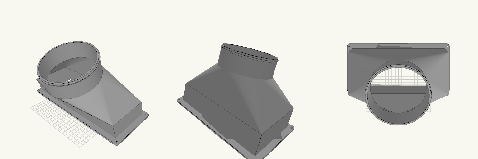
Rectangular-to-round exhaust adapter for routing a 150 mm vent hose from a Klarstein DryFy Connect 50L dehumidifier. The part bolts over the unit's 285 × 120 mm rectangular exhaust port and rises through a 50 mm straight rectangular section before lofting to a round spigot that slides inside a 150 mm hose. The rectangular body leans 20° toward -Y, and the spigot carries a further 20° tilt in the same direction, so the hose leaves the unit well off vertical. The rear of the spigot is pulled back into line with the rear wall of the leaning body, so the back of the adapter is one straight, continuous face with no bulge or kink at the transition; the front still curves as the rectangle narrows to the round spigot. The flange sits flat on the print plate; the overhanging body and spigot will need support. Specifications Overall size: 315 × 220.9 × 186.3 mm as it sits on the print plate Mounting flange: 315 × 150 mm, 4 mm thick, sized to cover a 285 × 120 mm rectangular port Four 4.5 mm screw holes, one in each flange corner Straight rectangular section: 50 mm tall above the flange, leaned 20° toward -Y Transition: 60 mm loft from the rectangle to a round spigot Hose spigot: 148 mm outside diameter, 50 mm long, set at 20° toward -Y on top of the body lean, for a 150 mm hose Combined body lean and spigot tilt put the hose axis roughly 40° off vertical, toward -Y Straight back face: spigot rear wall aligned with the rear wall of the leaning body Retaining ridge near the spigot end Wall thickness: 2.4 mm The angled spigot ends in an elliptical cut face; the hose slides on along the tilted axis Flange sits flat on the print plate; supports required under the leaning body and spigot Screw hole positions are a nominal layout; check them against the actual port before printing if an exact screw match is required The rectangle-to-round change is steep over 60 mm; expect visible stepping on the loft unless printed with fine layers Check that the angled spigot clears the wall or obstructions behind the unit before printing
Barbed End Plug for 1-Inch PEX
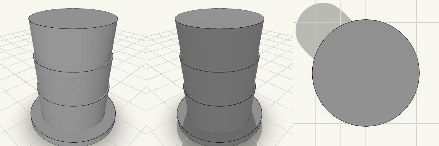
A barbed end plug that dead-ends a 1-inch PEX line. Three tapered barbs rise from a solid 28 mm collar cap, stacked directly on one another so each ring sits flush against the next with no gaps, and they taper from 21 mm to a 22 mm maximum diameter to suit pipe with roughly a 22 mm inner diameter. The collar is a 28 mm cylinder, 3 mm thick, with a 1 mm chamfer on the bottom outer edge, and it is the cap as well as the pipe stop — only about 3 mm of it shows past the barbs, so the stop is shallow. There is no bore: the plug is solid through, about 33 mm tall, sits flat on the plate, and prints as one piece as a 28 × 28 × 33 mm body. Because it seals rather than joins, check the barb fit against your actual pipe before committing to a full run. Remix hooks Barb profile: three tapered barbs stacked flush as one sawtooth suit roughly 22 mm inner diameter pipe. Change the count or soften the taper for harder or softer tubing, but keep the spacing equal to the barb height so the gaps between rings do not come back. Collar: 28 mm across and 3 mm thick, it is only just wider than the barbs. Widen or thicken it for a firmer insertion stop; the bottom outer edge carries a 1 mm chamfer, which can be enlarged or removed to change entry feel. Height: 33 mm overall is a compact cap; stretch the straight run above the barbs if you need more insertion room or a deeper seat. Barb diameter: 21–22 mm is the number to change first for other pipe sizes. The collar and barb spacing can stay put while only the taper moves. Ends: the solid cap is the safe baseline. Extending the same barbed profile out the other side turns it back into a straight coupling, and an elbow or tee is a body swap rather than a barb redesign. Fit check: barb dimensions are nominal, so test against your actual pipe before printing a full run. Pairs with: 1-inch PEX runs that need a temporary or permanent dead end, pressure testing, and capping a line before fixtures go on.
Perilla de estufa de repuesto con vástago reforzado
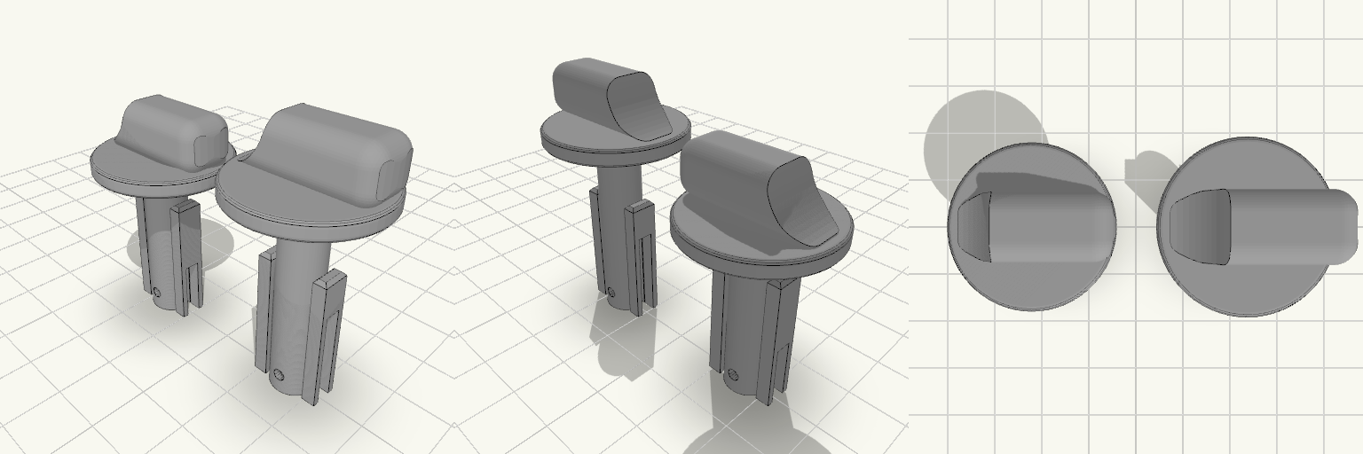
La perilla de la estufa que gira en falso o se parte deja el fuego sin control; esta perilla de repuesto se calza sobre el caño de gas y se traba con pasador, con el pulgar recortado al contorno del collar y todos los bordes del agarre redondeados para girar sin engancharse. La placa trae dos perillas: la original y una copia con vástago de 35 mm para cambiar el largo según la estufa. Cotas que deciden el calce Dos perillas en la misma placa: la original mide 41,5 mm de alto total (12 mm de cabeza + 29,5 mm de vástago); la copia mide 47 mm de alto total (12 mm de cabeza + 35 mm de vástago). En la placa ocupan 58 × 26 × 47 mm. Vástago: 8 mm de diámetro exterior, con dos aletas planas de refuerzo de 24 mm a los lados; en la copia, las aletas quedan en la zona de la punta. Vástago hueco: orificio de 5,5 mm de diámetro, abierto en la punta. En la original llega a 26 mm de profundidad y queda ciego en los últimos 3,5 mm hacia la cabeza, con paredes de aproximadamente 1,25 mm; la copia mantiene el mismo orificio de 5,5 mm. Agujero pasante: 2,2 mm de diámetro, horizontal, con el centro a 3,5 mm del extremo inferior; cruza la cavidad del vástago, así que la chaveta atraviesa el caño de gas. Endija: 3 mm de ancho, abierta en la punta; va a 90° del agujero del pasador, atraviesa el vástago y corta también las aletas laterales, dejando el extremo dividido en dos mitades flexibles. En la original llega a 11 mm; en la copia llega a 17,5 mm, la mitad de su vástago. Cabeza: collar de 26 mm de diámetro por 3 mm de alto; el pulgar mide 26 mm de ancho, 10 mm de grosor y 9 mm de alto sobre el collar, ya no pasa el contorno del collar, es plano de un lado y baja curvo del otro. Todas las aristas del pulgar tienen 3 mm de radio; los bordes del collar tienen 0,8 mm. Cada perilla se imprime de una sola pieza; la endija no separa el modelo, solo deja flexibles las dos mitades del extremo. El acabado negro mate sale del filamento que elijas, no de la geometría. Antes de imprimir, mide el diámetro del caño de gas y el del pasador: el hueco del vástago y el agujero pasante son las dos cotas que no perdonan, y si no coinciden es mejor ajustarlas antes de gastar material.
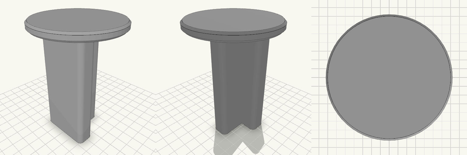
T-Post Cap With 3-Inch Round Platform
A slip-on cap for a steel T-post: 4 in tall, with a T-shaped socket that drops over the post and a 3 in round platform, 1/4 in thick, on top. Fits Steel T-posts, matched to the T-socket below. The socket is a T: a 36 mm crossbar, 7 mm wide at the stem entry, with a 7 × 30 mm stem running down, and a 4 mm wall following that T all the way around. Takes the place of a plain post cap and adds a flat, 3 in round surface on top of the post. Check before printing The socket is the whole fit, and its numbers are a starting size, not a standard — T-posts differ in flange width and web thickness between manufacturers and post weights. Measure the post you intend to use across the crossbar, across the stem, and across the full depth, then set the socket to those sizes plus a little clearance for paint and burrs before you commit filament. Nothing else on the part affects fitment. Does not fit Round posts, wooden 4x4 posts, or any post without a T cross-section. T-posts whose crossbar or stem is wider than the socket above — T-post profiles are not interchangeable, so do not assume a fit from the post name or the post weight alone. The cap prints as a single piece, 76 × 76 × 102 mm overall.
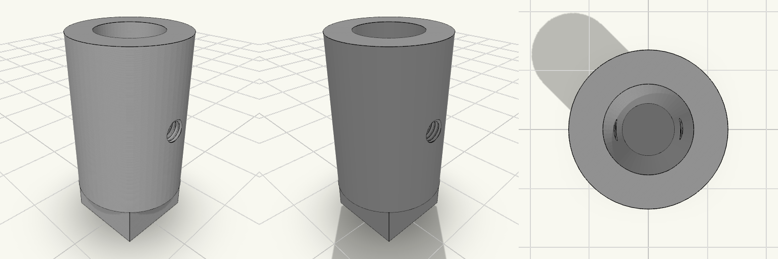
Barra cilíndrica con base cuadrada sólida
Para qué sirve Es una barra cilíndrica vertical de Ø14 mm sobre una base cuadrada maciza de 10 × 10 mm. La base y la barra comparten eje, y el agujero central de Ø8 mm empieza justo encima de la base: la base queda cerrada por abajo. Sirve como separador, pie de apoyo o guía para un vástago o tornillo que entre por arriba. A media altura de la barra hay dos agujeros laterales roscados M3, diametralmente opuestos, que llegan hasta el agujero central. Cada rosca permite enroscar un tornillo M3, uno por lado, para fijar lo que se introduzca en el agujero central o para sujetar la barra a otra pieza. La barra es más ancha que la base y sobresale 2 mm por cada lado. Dimensiones Barra: Ø14 mm exterior, con 20 mm de altura sobre la base. Agujero central: Ø8 mm, concéntrico, solo en la barra (no atraviesa la base). Agujeros laterales: dos roscados M3 de paso 0,5 mm, opuestos, a 15 mm de altura (mitad de la barra), pasantes hasta el agujero central. Base: cuadrada de 10 × 10 mm, sólida, con 5 mm de espesor. Altura total: 25 mm. Pared entre el agujero central y el exterior de la barra: 3 mm por lado. Tamaño en la cama: 14 × 14 × 25 mm. Notas de impresión La base plana de 10 × 10 mm se apoya directamente en la cama. La barra sobresale 2 mm por cada lado sobre la base; ese pequeño vuelo suele imprimirse sin soportes con buena refrigeración. Conviene imprimirla en vertical, tal como está orientada, para que el agujero central quede limpio y sin escalones. El fondo cerrado del agujero actúa como tope: un vástago introducido desde arriba no sobresale por debajo. Los tornillos M3 que se enrosquen en los laterales no deben pasar de unos 6 mm de rosca: con la pared de 3 mm, la punta queda dentro del agujero central sin tocar la pared opuesta. Las roscas M3 impresas pueden salir justas; después de imprimir, conviene pasar un macho de M3 por cada agujero lateral para limpiarlas. La base es más pequeña que la barra: si se necesita más superficie de apoyo o de pegado, conviene ampliarla. Ideas de remezcla Ampliar la base cuadrada a 14 × 14 mm o más para igualarla con el diámetro de la barra y ganar estabilidad. Alargar el tramo de barra por encima de la base para adaptarlo a la altura que necesites. Cambiar el diámetro del agujero central o el tamaño de las roscas laterales para que encajen un tornillo o un tubo concretos. Añadir un chaflán o un radio en el borde superior de la barra para facilitar la entrada de un vástago.