Barbed End Plug for 1-Inch PEX
Created yesterday
Description
A barbed end plug that dead-ends a 1-inch PEX line. Three tapered barbs rise from a solid 28 mm collar cap, stacked directly on one another so each ring sits flush against the next with no gaps, and they taper from 21 mm to a 22 mm maximum diameter to suit pipe with roughly a 22 mm inner diameter. The collar is a 28 mm cylinder, 3 mm thick, with a 1 mm chamfer on the bottom outer edge, and it is the cap as well as the pipe stop — only about 3 mm of it shows past the barbs, so the stop is shallow. There is no bore: the plug is solid through, about 33 mm tall, sits flat on the plate, and prints as one piece as a 28 × 28 × 33 mm body. Because it seals rather than joins, check the barb fit against your actual pipe before committing to a full run.
Remix hooks
- Barb profile: three tapered barbs stacked flush as one sawtooth suit roughly 22 mm inner diameter pipe. Change the count or soften the taper for harder or softer tubing, but keep the spacing equal to the barb height so the gaps between rings do not come back.
- Collar: 28 mm across and 3 mm thick, it is only just wider than the barbs. Widen or thicken it for a firmer insertion stop; the bottom outer edge carries a 1 mm chamfer, which can be enlarged or removed to change entry feel.
- Height: 33 mm overall is a compact cap; stretch the straight run above the barbs if you need more insertion room or a deeper seat.
- Barb diameter: 21–22 mm is the number to change first for other pipe sizes. The collar and barb spacing can stay put while only the taper moves.
- Ends: the solid cap is the safe baseline. Extending the same barbed profile out the other side turns it back into a straight coupling, and an elbow or tee is a body swap rather than a barb redesign.
- Fit check: barb dimensions are nominal, so test against your actual pipe before printing a full run.
- Pairs with: 1-inch PEX runs that need a temporary or permanent dead end, pressure testing, and capping a line before fixtures go on.
Images
More like this
Explore more in Home & Fixtures →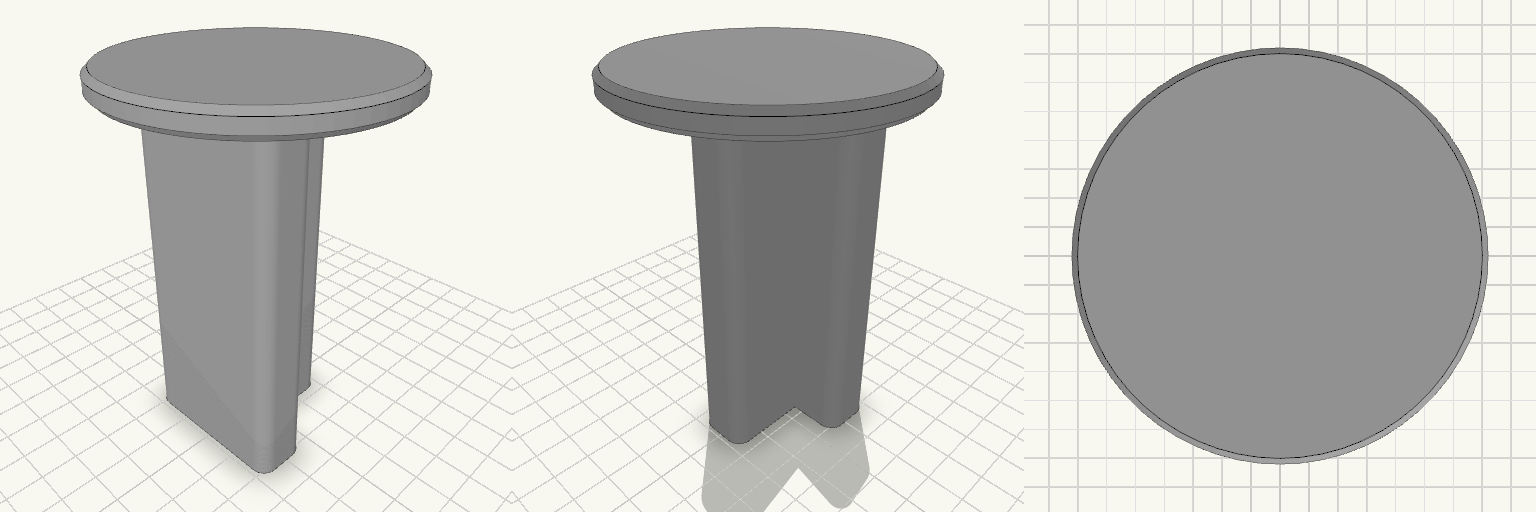
T-Post Cap With 3-Inch Round Platform
A slip-on cap for a steel T-post: 4 in tall, with a T-shaped socket that drops over the post and a 3 in round platform, 1/4 in thick, on top. Fits Steel T-posts, matched to the T-socket below. The socket is a T: a 36 mm crossbar, 7 mm wide at the stem entry, with a 7 × 30 mm stem running down, and a 4 mm wall following that T all the way around. Takes the place of a plain post cap and adds a flat, 3 in round surface on top of the post. Check before printing The socket is the whole fit, and its numbers are a starting size, not a standard — T-posts differ in flange width and web thickness between manufacturers and post weights. Measure the post you intend to use across the crossbar, across the stem, and across the full depth, then set the socket to those sizes plus a little clearance for paint and burrs before you commit filament. Nothing else on the part affects fitment. Does not fit Round posts, wooden 4x4 posts, or any post without a T cross-section. T-posts whose crossbar or stem is wider than the socket above — T-post profiles are not interchangeable, so do not assume a fit from the post name or the post weight alone. The cap prints as a single piece, 76 × 76 × 102 mm overall.
Klarstein DryFy 50L 150 mm Exhaust Adapter
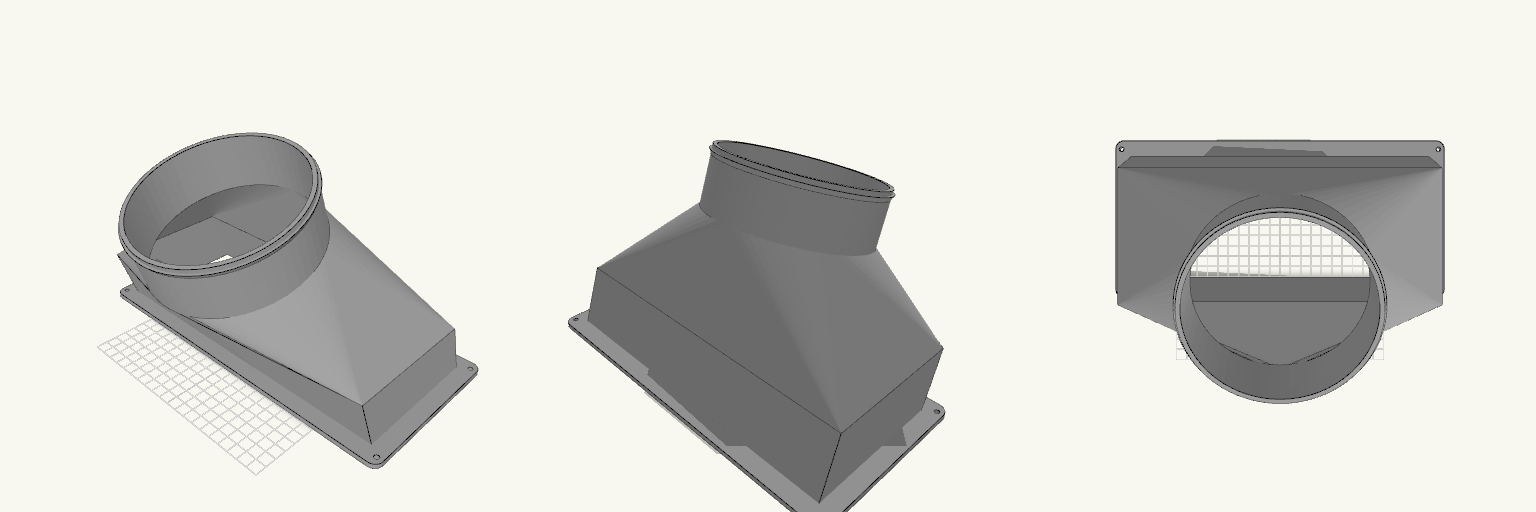
Rectangular-to-round exhaust adapter for routing a 150 mm vent hose from a Klarstein DryFy Connect 50L dehumidifier. The part bolts over the unit's 285 × 120 mm rectangular exhaust port and rises through a 50 mm straight rectangular section before lofting to a round spigot that slides inside a 150 mm hose. The rectangular body leans 20° toward -Y, and the spigot carries a further 20° tilt in the same direction, so the hose leaves the unit well off vertical. The rear of the spigot is pulled back into line with the rear wall of the leaning body, so the back of the adapter is one straight, continuous face with no bulge or kink at the transition; the front still curves as the rectangle narrows to the round spigot. The flange sits flat on the print plate; the overhanging body and spigot will need support. Specifications Overall size: 315 × 220.9 × 186.3 mm as it sits on the print plate Mounting flange: 315 × 150 mm, 4 mm thick, sized to cover a 285 × 120 mm rectangular port Four 4.5 mm screw holes, one in each flange corner Straight rectangular section: 50 mm tall above the flange, leaned 20° toward -Y Transition: 60 mm loft from the rectangle to a round spigot Hose spigot: 148 mm outside diameter, 50 mm long, set at 20° toward -Y on top of the body lean, for a 150 mm hose Combined body lean and spigot tilt put the hose axis roughly 40° off vertical, toward -Y Straight back face: spigot rear wall aligned with the rear wall of the leaning body Retaining ridge near the spigot end Wall thickness: 2.4 mm The angled spigot ends in an elliptical cut face; the hose slides on along the tilted axis Flange sits flat on the print plate; supports required under the leaning body and spigot Screw hole positions are a nominal layout; check them against the actual port before printing if an exact screw match is required The rectangle-to-round change is steep over 60 mm; expect visible stepping on the loft unless printed with fine layers Check that the angled spigot clears the wall or obstructions behind the unit before printing
Eccentric Duct Adapter 125mm
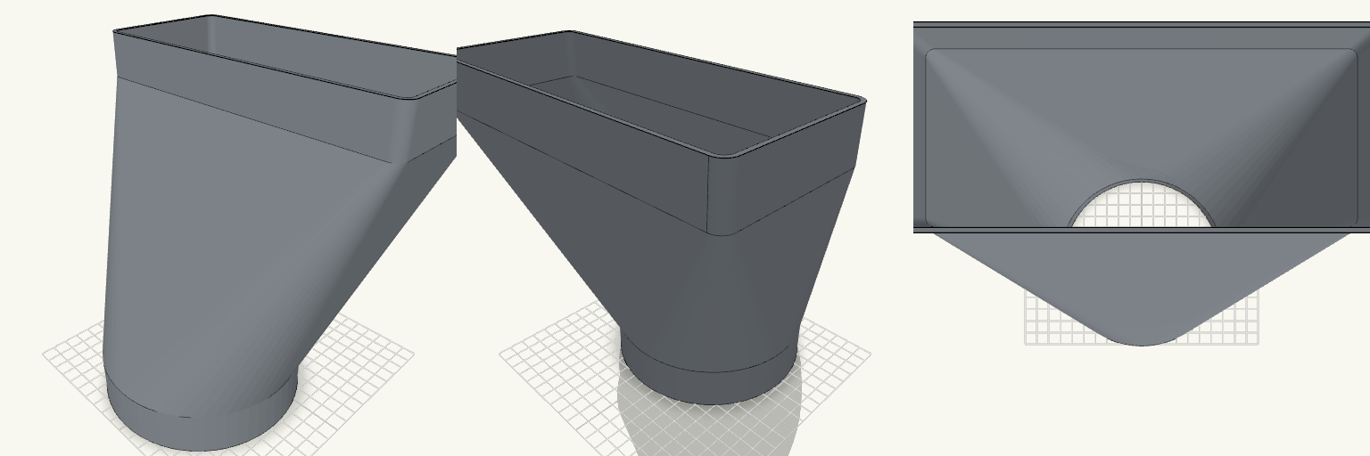
What it's for Bathroom duct adapter that joins a round duct to a flat rectangular duct in one continuous piece. Both ends are female sockets, so the ducts slide into the adapter rather than over it, and the internal passage stays fully open from end to end with no obstruction to airflow. The round socket is bored to Ø132 mm for a free, loose fit over Ø125 mm duct — roughly 3.5 mm of clearance per side, which can be taken up with tape or a gasket if a tighter seal is wanted. Dimensions Round socket: Ø132 mm inner, Ø136.8 mm outer, 30 mm long, 1.5 mm entry chamfer Flat socket: 222 × 92 mm inner, 5 mm corner radius, 30 mm long Transition: 160 mm, smooth round-to-rectangle loft, horizontally symmetric Vertical offset of the flat socket: 72.5 mm Wall thickness: 2.4 mm throughout Overall length: 220 mm Print notes Print as one piece; no assembly and no supports are needed for the open bore. The bounding volume on the plate is about 227 × 189 × 220 mm, so check the build volume before slicing. A 2.4 mm wall prints cleanly in PETG or ABS if the part sees warm bathroom air; PLA works for a dry run-in fit. Remix ideas Change the bore diameter to tune the fit for a different round duct. Adjust the 72.5 mm vertical offset for another mounting position. Lengthen either socket for a deeper grip on the duct.
90 Degree Water Elbow, 5 mm Bore
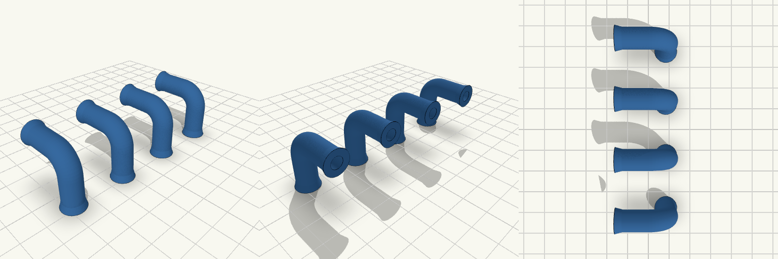
A set of four identical 90 degree elbow fittings for water lines, each with a 5 mm inside diameter and a 2 mm wall. Each elbow has a smooth curved bend and two straight 14 mm legs. A small ridge at each leg end helps hold a tube in place. Inside diameter: 5 mm Outside diameter: 9 mm (2 mm wall) Leg length: 14 mm each Bend radius: 8 mm at the centreline Quantity: 4 identical elbows, spaced 25 mm apart
Glue-On Snap Latch for Fly Screen Frames
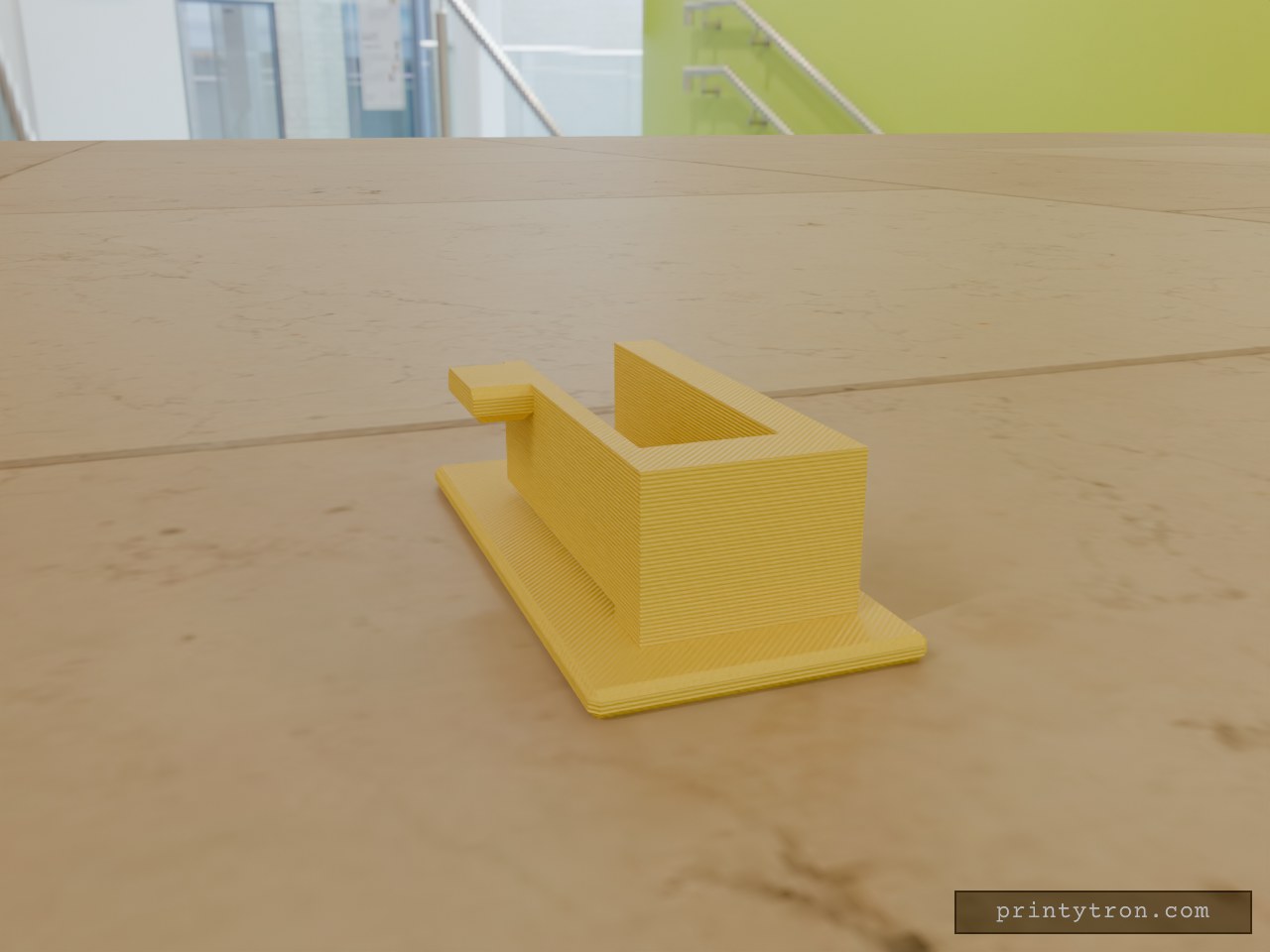
A fly screen frame that lifts out of its catch every time the door moves needs a latch that holds it and lets go on demand. This one glues to the wall, the frame presses into the slot and snaps past the hook, and a thumb tab on the outside of the arm pulls the hook clear. One hand does both jobs — no second hand holding the frame, no screwdriver. Fit Slot: 10.4 mm wide, sized for a 10 mm frame with 0.4 mm clearance. Base plate: 50 × 24 mm, 2 mm thick, with two shallow relief pockets underneath to hold the glue. Snap arm: 30 mm long, 1.8 mm thick. Printing One piece. No screws, no loose parts, nothing to assemble. Print standing as modelled, so the layers run across the arm's bend rather than along it. PETG suits the flex the snap arm needs. Measure the standoff between wall and frame before gluing: the base plate is 2 mm thick, so it sits in the gap rather than spanning it. Snap strength and tab size are the two things to adjust if the catch is too stiff or too easy for the frame you have.
T-Post Cap With 2.5-Inch Round Platform
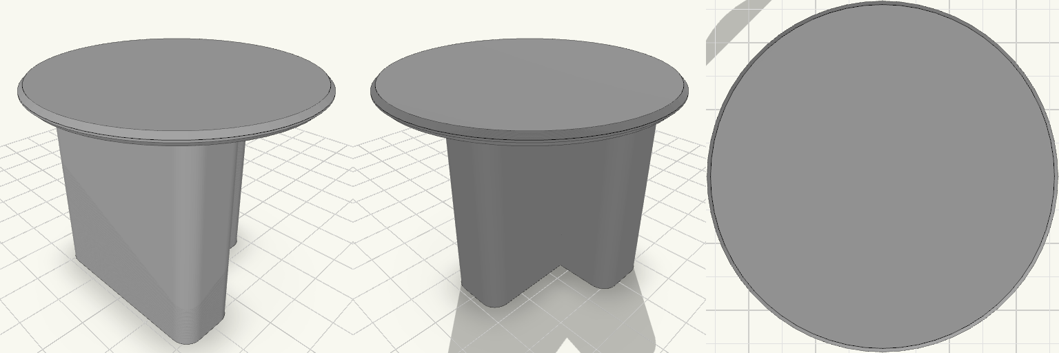
A slip-on cap for a steel T-post: 4 in tall, with a T-shaped socket that drops over the post and a 3 in round platform, 1/4 in thick, on top. Fits Steel T-posts, matched to the T-socket below. The socket is a T: a 36 mm crossbar, 7 mm wide at the stem entry, with a 7 × 30 mm stem running down, and a 4 mm wall following that T all the way around. Takes the place of a plain post cap and adds a flat, 3 in round surface on top of the post. Check before printing The socket is the whole fit, and its numbers are a starting size, not a standard — T-posts differ in flange width and web thickness between manufacturers and post weights. Measure the post you intend to use across the crossbar, across the stem, and across the full depth, then set the socket to those sizes plus a little clearance for paint and burrs before you commit filament. Nothing else on the part affects fitment. Does not fit Round posts, wooden 4x4 posts, or any post without a T cross-section. T-posts whose crossbar or stem is wider than the socket above — T-post profiles are not interchangeable, so do not assume a fit from the post name or the post weight alone. The cap prints as a single piece, 76 × 76 × 102 mm overall.