Phone Clamp 60-85mm with 1/4-20 Socket
Created 5 days ago
Description
U-shaped spring clamp that holds a phone across its back and bolts to the centre screw of a ring light. The two jaws grip the phone's long edges. The rest opening is 58 mm and the jaws flex to about 85 mm. Separate soft pads sit on the inner faces to protect the phone's edges.
The base has a 1/4-20 through hole with a hex nut pocket on the underside. Two slots cut into the base give the jaws room to spring. Each jaw ends in a retaining lip that stops the phone from lifting out.
Specs
- Opening: 60-85 mm, 58 mm at rest
- Mount: 1/4-20 through hole (6.6 mm) with a 12.2 mm hex nut pocket
- Jaw thickness: 2.6 mm
- Jaw width: 22 mm
- Overall size: about 63 x 14 x 36 mm
- Clamp body material: PETG suggested, for spring flex
- Pad material: TPU suggested, printed as separate pieces
- Spring travel: not tested, so check the flex before loading a phone
- Use cases: ring light phone mount, filming, content creation setups
Images
More like this
Explore more in Desk & Tech →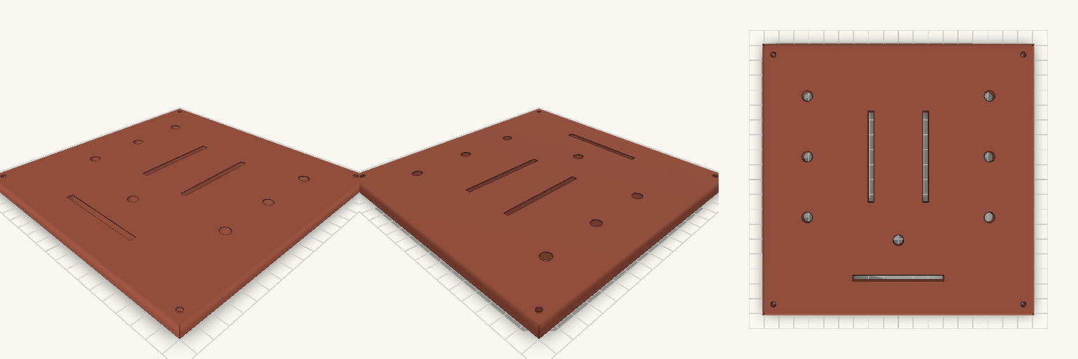
Tapa 180x180 con 3 crossfaders y 7 potenciómetros
Tapa de 180 × 180 × 5 mm para un controlador DJ, con tres ranuras de crossfader y siete agujeros de potenciómetro de 7 mm. Medidas a comprobar Ranuras de crossfader: 60 × 4 mm (el largo total del recorte según la ficha de tu modelo). Agujeros de potenciómetro: 7 mm, seis a ±60 mm en X y uno central en X = 0, Y = −40 mm. Cuatro tornillos M3 avellanados en las esquinas. No incluye Taladros de fijación de los crossfaders ni de los potenciómetros.
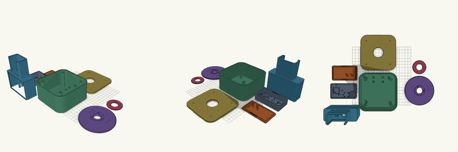
Modular Voice Assistant Enclosure with Rotating Desk Dock
A two-part enclosure system for a modular AI voice assistant: a pocket-sized "Brain" that works on its own, and a desktop station that docks it, swivels a full 360° and carries a 3.5-inch touchscreen behind a removable bezel. Both halves share the same matte-black design language — rounded corners, smooth surfaces and 2–2.5 mm walls — and print as eight separate pieces. What it's for Brain — houses an ESP32-S3 N16R8 board, an INMP441 I2S microphone, a MAX98357A amplifier and a 20 mm speaker behind a grille. A circular LED ring glows through a 0.8 mm front skin for listening, thinking and speaking states; there is no display of its own. A USB-C port sits on the short end, and the unit runs standalone once lifted off the dock. Desk station — a weighted base with a bolted lid carries a swivel plate and the dock tower. The Brain drops into the tower pocket from above with its face still visible, and a USB-C plug cradle in the pocket floor lines up with the port. Display — the tower front takes a standard 98 × 56 mm touchscreen module in landscape, held on four M2 bosses and framed by a bezel that drops into a recess in the front face. Removing four screws frees the display for replacement, and a flat-cable slot below the opening routes the ribbon into the cavity. Rotation — the swivel plate's hollow stem passes through the lid, a retaining ring screws on underneath, and the cable runs down the centre of the stem, so the tower turns 360° without twisting the lead. Dimensions Brain: 85 × 50 × 25 mm overall, with a snap-fit rear cover. Desk base: 120 × 120 mm with 22 mm corner radii; base, lid and swivel plate stack to 65 mm. Dock tower: 104 × 40 × 119 mm, docking the Brain vertically above the display section. It overhangs the 100 mm swivel plate slightly at the front and rear corners. Display opening: 84 × 54 mm, with mounting bosses behind the wall at ±46 × ±25 mm and M2 pilot holes; bezel 100 × 60 × 2.5 mm. Walls: 2–2.5 mm throughout hollow cavities. Print notes Print the Brain shell face-down for a smooth front skin; the LED ring, microphone port and speaker grille all sit in that face. The rear cover snaps on with two bump-and-groove pairs along the long sides; pads on its inside hold the ESP32 down. The tower's internal floor and the display window bridge wide spans, so expect a little support in the dock tower only. Everything else is oriented to print without it. Print the bezel flat; it is a thin frame and needs no supports. PLA or PETG both work; four rubber-foot recesses under the base are worth filling. All eight pieces — Brain shell, rear cover, desk base, base lid, swivel plate, retaining ring, dock tower and display bezel — are separate. The lid bolts on at four corners and the display bezel screws in from the front. Compatibility The display bosses use M2 pilot holes; check your module's hole spacing before driving screws, since pinouts vary between boards. The dock pocket is sized for the Brain as drawn — if you change the Brain's shell, adjust the pocket in step. Remix ideas Lean the dock back a few degrees for a more natural viewing angle if you can accept the extra support. Swap the removable bezel for a blank panel or a vent if your build has no screen. Scale the docking pocket to fit a different companion device while keeping the same swivel mechanism.
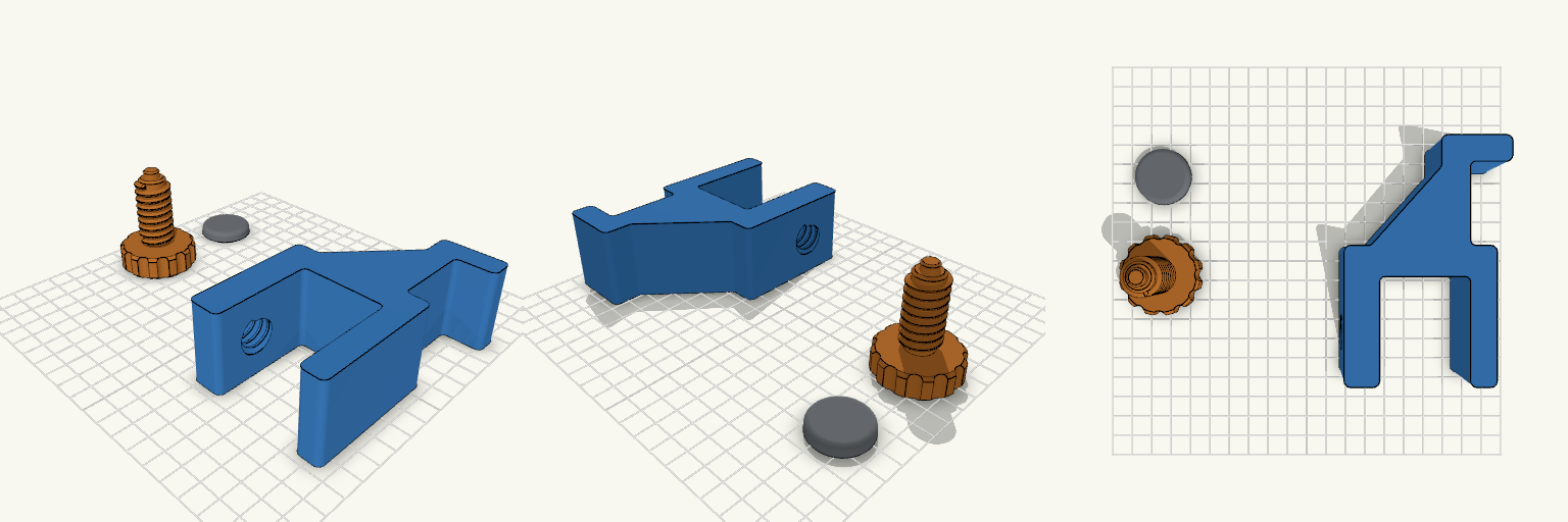
Perch — Clamp-On Headphone Holder
Perch is a three-piece desk-edge headphone holder: a main body with hook and clamp jaws, a separate threaded adjustment screw with a large scalloped knob, and a loose pressure pad. Nothing is joined or printed in place, so the parts are laid out separately and assembled by hand after printing. Features Clamp range of 15–35 mm, suited to a 20 mm desk Internal thread in the lower jaw with 0.4 mm radial clearance for the 18 mm, 4 mm-pitch screw 40 mm knob with scalloped grip Pad snaps onto an 8 mm peg at the screw tip and spins freely Reinforced hook with gusset and rounded lip Print notes Body on its side, screw knob-down, pad flat PLA, 0.4 mm nozzle, 0.20 mm layers, 4 walls No supports expected Assembly Thread the screw up through the lower jaw from below, then press the pad onto the peg. Set the source's mode value to 1, 2 or 3 to export each part individually.
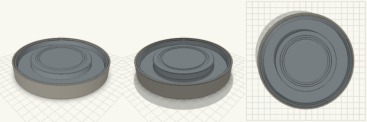
Nested Condensation Coaster with Removable Basin Insert
What it's for A two-part coaster for a glass or mug on a desk. The cup rests flat on the raised platform of the removable insert — nothing is inserted into a sleeve or ringed by walls — and condensation running down the glass collects in the basin around the platform. The outer shell is a second, watertight barrier that catches anything the insert lets past, and there are no drainage holes or outlets anywhere, so the water stays put until the insert is lifted out and emptied. The two parts print separately and can be cleaned separately. Outer Containment Shell — one continuous watertight body, open at the top so the inside is fully accessible with the insert out. Four integrated pillars support the insert. Inner Insert — raised cup platform, recessed collection basin, and a groove in the platform floor for a removable silicone grip ring. Support pillars — four 8 mm round pillars, 90° apart on a 58 mm radius, rising from the shell floor to hold the insert 3.5 mm clear of the bottom. Silicone provisions — a grip-ring groove in the recess floor and four pockets underneath the shell for non-slip feet. The silicone parts themselves are not printed. Dimensions Outer shell: 148 mm diameter, 22 mm tall, 2.4 mm walls, 3 mm base. Inner insert: 141.8 mm diameter, 13.5 mm tall, sitting 3.5 mm above the shell floor with 0.7 mm clearance per side. Cup platform: 95 mm diameter, top surface at 19 mm height. Locating recess: 80 mm diameter, 1 mm deep, in the platform top. Grip-ring groove: 1.5 mm deep, between 34 and 37 mm radius, in the recess floor. Basin: about 24 mm wide and roughly 10.5 mm deep at the wall, holding approximately 55–65 ml before it overflows into the shell. Foot pockets: four at 10 mm, 1 mm deep, on a 58 mm radius circle, directly below the pillars. Print notes Print both parts in PETG with four or more perimeters — the shell's wall seal is what keeps the desk dry. The shell's foot pockets stop short of the inside floor, so the base stays closed. Watch first-layer elephant foot on the shell's outer base edge; it can make the part rock. The shell rim stands 2 mm above the insert, and the space under the insert adds further secondary containment, so overflow is caught. The pillars print flat-bottomed with no supports, and the open gap under the insert allows inspection and drying after use. Remix ideas Add a lift tab or finger notch to the insert rim — as it stands the tight gap means a wet insert may need a thumbnail or thin tool to lift, though the open underside helps. Add a small locating dimple to the insert underside to stop it sliding its 0.7 mm of play. Widen the platform for larger mugs; cups wider than 95 mm overhang the platform and drip into the basin, which works but is less stable. Increase the insert height or basin depth if you want more collection capacity. Swap the four-pocket foot pattern for a continuous silicone band if the coaster lives on a slippery surface.
Octobay — 5.25" to 3.5" Drive Cage
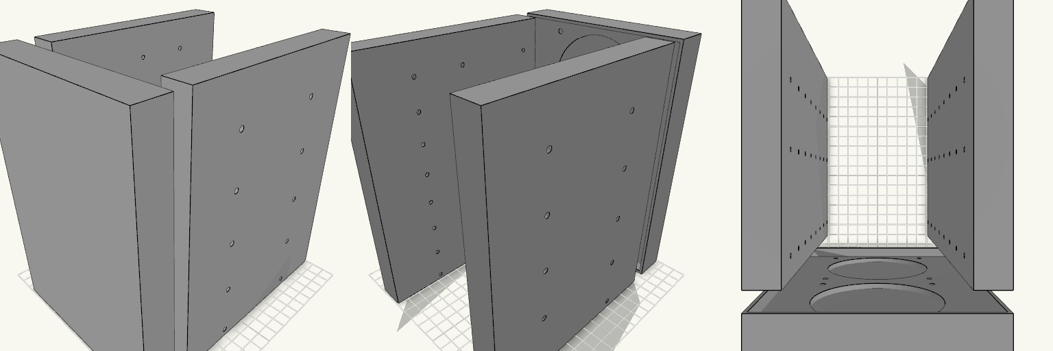
Octobay turns a five-bay stack of half-height 5.25" slots into room for eight 3.5" drives, and adds a 25 mm front cage that carries two 92 mm fans. The outer side faces take M3 heat-set inserts, so the whole cage screws into the case's 5.25" rails instead of resting on them. Everything is one printed part: the drive stack, the side mounting blocks and the fan cage print as a single body. Because the fans close off the front, drives now load from the back. The fan cavity behind the grille is hollow, so air still passes through to the drive stack. Dimensions Overall: 145 mm wide × 197.5 mm deep × 205.5 mm tall Fits: five half-height 5.25" bays Holds: eight 3.5" drives, stacked vertically Drive channel: 102.6 mm wide — 1 mm of play around a 101.6 mm drive Mounting 20 insert holes, 10 per side, for M3 heat-set inserts — 4.2 mm across and 6 mm deep Two insert holes per bay, at 41.3 and 117.5 mm from the front, 6.35 mm above each bay floor Solid blocks sit behind each hole to give the inserts something to bite into Three M3 screw holes per side per drive, at 14, 76.6 and 117.6 mm from the front Cross ribs sit clear of the screw holes so a screwdriver can reach every fastener Fan cage Two 92 mm fans, stacked vertically on the 25 mm front section 88 mm fan openings with 4.4 mm screw holes on the standard 82.5 mm square pattern Hollow cavity behind the fans feeds air to the drive channels Print notes Drive channels are open at the back, top and bottom, and the gaps between the inner and outer side walls are open for cable routing. Screw and insert positions and the 205.5 mm height follow common 5.25" bay standards; they have not been checked against a specific case, so measure your bay rails and drives before printing.
Fidget Slider Toy, Captive Print-in-Place
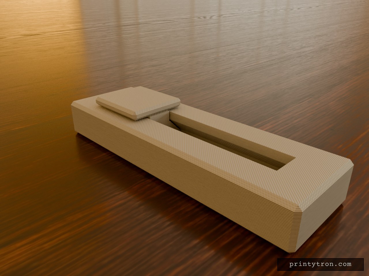
A fidget slider that prints already assembled, so there is no loose weight to lose and nothing to glue. The slider is captured in an enclosed dovetail track and cannot fall out. It runs 40 mm end to end and clicks at each stop instead of rolling freely. What it does Slides back and forth along a closed track in an 80 x 25 mm body. A small bump on the track floor at each end of travel drops into a dimple under the slider and gives the click. The dovetail profile holds the slider down, so it cannot lift out of the rails. Numbers that matter Body: 80 x 25 x 11 mm, with the slider top reaching 14 mm. Slider: 20 mm long, 18 mm wide cap. Travel: 40 mm. Clearance between slider and track: 0.4 mm per side. This is what lets it move after printing. Click bump: about 0.6 mm of interference against the 0.4 mm gap. Reduce the bump height if it feels too stiff. Printing Print flat, body base down, with no supports needed inside the track. Use a well-tuned printer. A 0.4 mm gap fuses easily if the flow is too high. After printing, work the slider back and forth a few times to break any thin bridging between the slider and the rails. Two colours show as separate parts in the preview, but the print is one job.