Apothecary Drawer Hex Key Rack
Created today
Description
A row of nine upright hex pockets, like a pharmacist's labelled vial rack, scaled down for the workshop wall. Each long-arm Allen key stands in its own slot, sorted from 1.5 mm up to 10 mm, with the metric size embossed on the front face beside it so the right key is readable at a glance.
Every pocket is a hex cut to its key's across-flats size plus 0.3 mm of clearance, 22 mm deep, so keys drop in and lift out without wobbling loose. Two counterbored screw holes near the ends let the rack mount flat to a wall.
Design notes
- Fits the standard metric set: 1.5, 2, 2.5, 3, 4, 5, 6, 8 and 10 mm
- Overall size about 120 mm wide, 20 mm deep, 30 mm tall
- Embossed labels are a separate colour region for multi-colour prints or a filament swap
- Chamfered outer edges for a cleaner print and a softer look
- The 1.5 mm slot is the tightest fit, so check it on a first print
- Remix hooks: change pocket depth, enlarge the label text, or add more slots for imperial sizes
Photos
Technical views
More like this
Explore more in Workshop & Tools →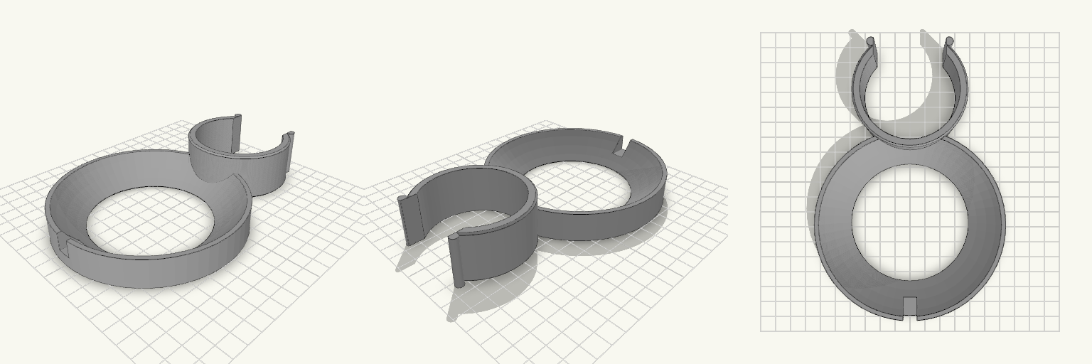
Drill Press Column Tray with Key Slot
A C-shaped clip that snaps around a 60 mm drill press column, with a 120 mm round dished tray attached at the front. The tray holds drill bits, chuck keys and small parts within reach while you work. The clip opening is narrower than the column, so it snaps on and grips by spring tension. Lead-in lips on both sides of the opening guide it onto the column. A slot on the front rim of the tray holds the chuck key, so it stays off the floor. Clip: fits a 60 mm column, 30 mm tall, 5 mm wall Tray: 120 mm diameter, 18 mm tall, with a 3 mm floor and a dished cavity Key slot: on the front rim, 9 mm wide, sized for a chuck key shaft Print the clip upright with the tray on the plate. PETG or ABS gives the clip better flex and durability than PLA.
Tape Spindle and Zip Tie Bench Caddy
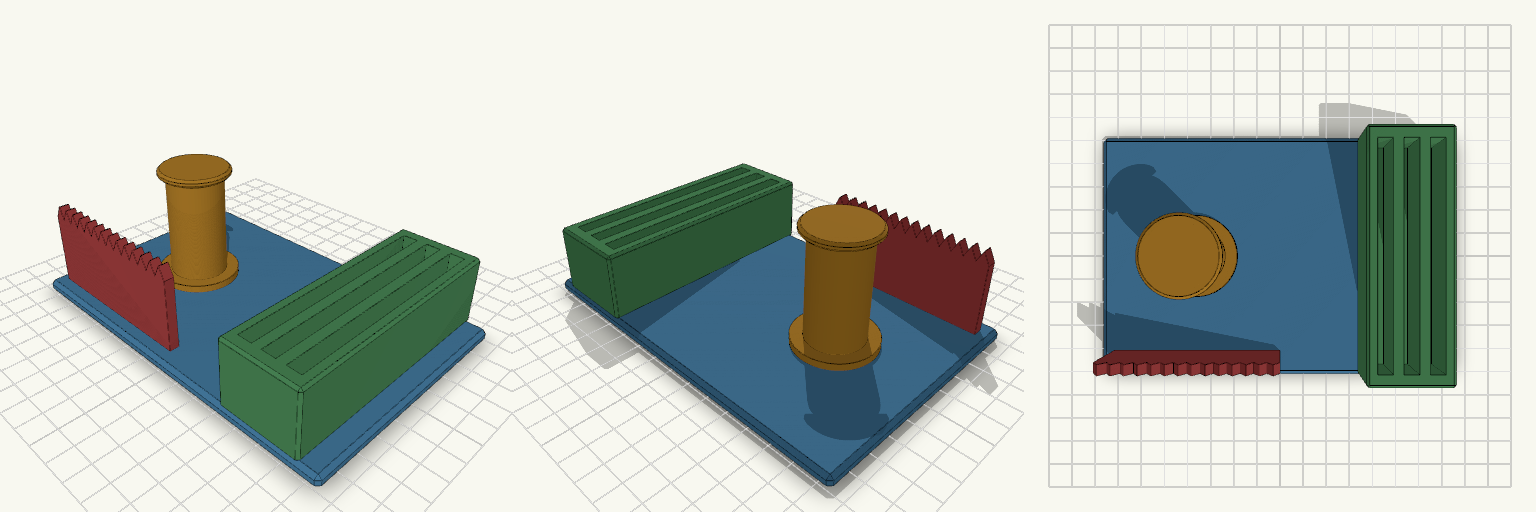
Bench caddy that keeps a tape roll and a bundle of zip ties in one fixed spot on the bench. A 24 mm spindle holds a roll with a 25 mm core. A serrated tear bar runs along the front edge so tape can be pulled across the teeth and torn. A block on the right has three slots for zip ties up to 90 mm long. Specs Base: 150 × 100 × 5 mm plate with 1.5 mm chamfered edges Spindle: 24 mm diameter, about 46 mm tall, with a 34 mm foot and a 30 mm top flange. Sized for a 25 mm core with 1 mm clearance. Tear bar: 70 mm long, 4 mm thick wall with 14 serrated teeth. It sits along the front (-Y) edge, beside the spindle. Tie trough: 34 × 100 mm block, 28 mm tall, with three 6 mm wide slots, each 90 mm long, in a row across X. Overall height: about 54 mm, measured at the top of the spindle flange. Material: PLA or PETG. Print flat on the base with no supports. Notes Fit has not been tested against a physical roll. If the roll is tight on the spindle, reduce the spindle diameter slightly. Slot width suits standard narrow zip ties. Wider ties need wider slots.
Folding Hex Easel Vise With Strut Links
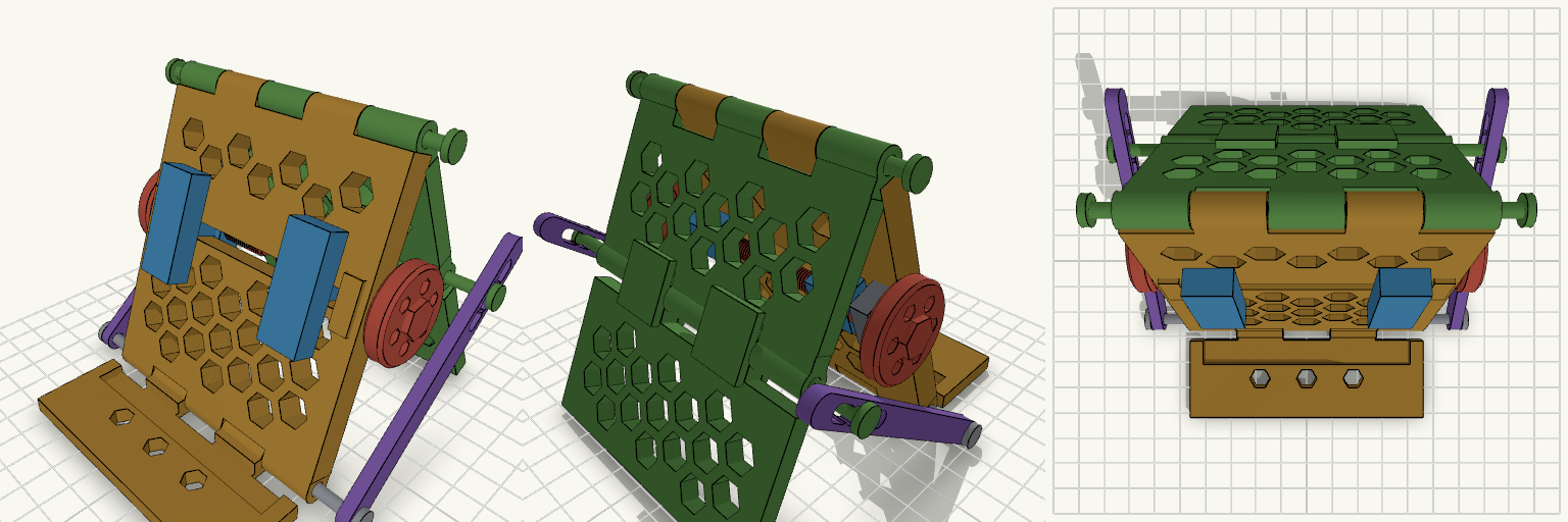
A folding bench-vise and easel stand: a honeycomb-cut backrest on a hinged base ledge, two jaws driven by threaded crank rods, and a rear support leg held by a two-stick folding strut on each side. The strut is built from two flat sticks joined at an elbow pin. Push the leg in and the elbow bends, so the two sticks fold down alongside each other and act as one. The sticks sit outside the handwheels in X, so they pass beside the cranks and not through them. Remix hooks link_k (0.52): stick length as a fraction of the base-to-knee distance. It must stay above 0.5. Higher values give a bigger elbow bow and a longer reach. platelean (20°) and legang (25°): raise them together for a steeper recline. rodz (60 mm) and jawx (27 mm): crank height and jaw start position. hd and wall in the hex cutter (11 mm and 3 mm): change them for a denser or sparser honeycomb. phonew, phonet and phone_d (80, 10.5 and 3 mm): the phone slot. leg_lock: switches the knee stop tabs on or off. Pairs with Longer or thicker stick bars (4 mm wide now) for heavier loads. 4 mm filament offcuts as hinge and elbow pins.
Hex Tube 40 mm Tall With Center Bore
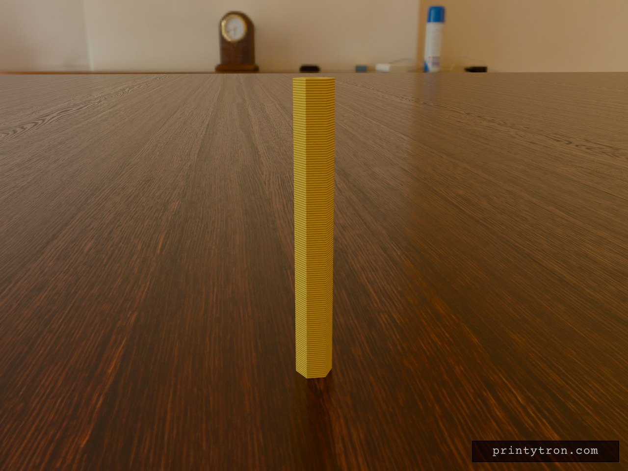
A hex tube, 4 cm tall, for when a round spacer or standoff spins or rolls where a flat-sided one would hold still. The 2.5 mm bore runs the full length so a rod, wire or screw passes straight through. Key dimensions Height: 40 mm Width: 5.15 mm point to point Center bore: 2.5 mm diameter, through the full length Printing Print standing upright, no supports needed. Walls are thin at the hex flats, so use at least 2 perimeters and a small nozzle if possible.
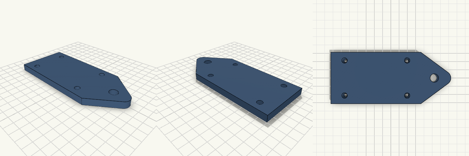
Industrial Pull Plate
A heavy-duty mounting plate featuring an integrated pull tab and precise counterbored holes. Designed for easy handling and a flush fit with socket head hardware. Mounting Interface: 4x 4.3mm thru-holes with 6.5mm counterbores (4mm deep) Spacing: 72mm x 40mm pattern Convenience: Rounded 35mm pull tab with a 10mm grip hole
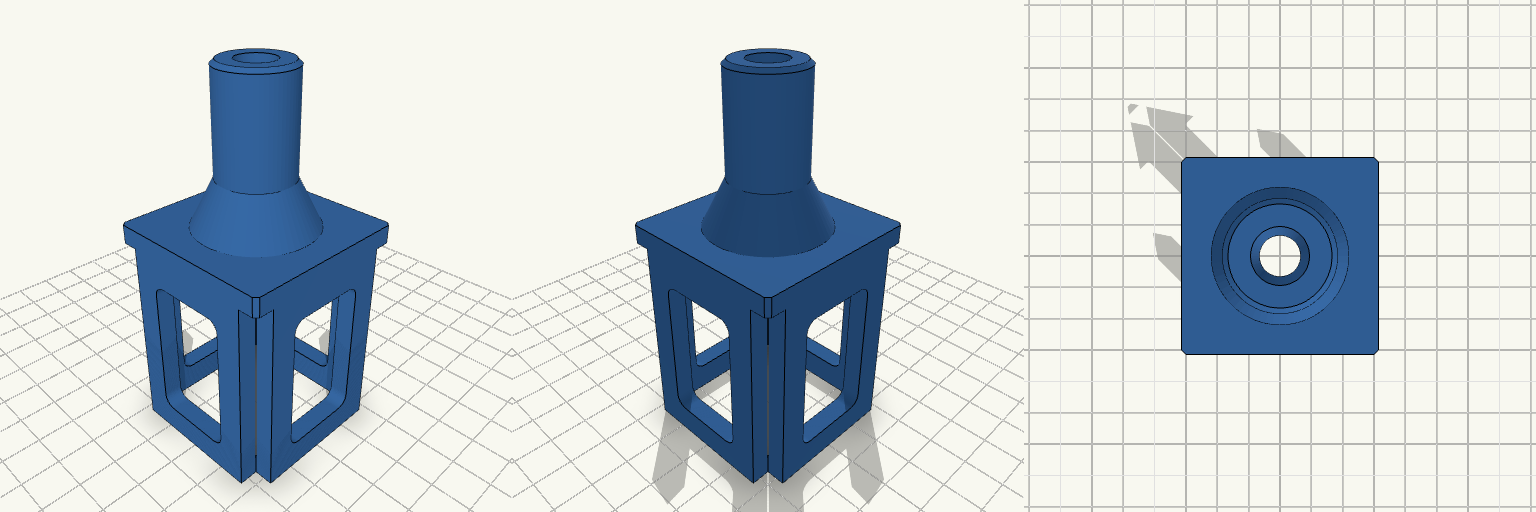
Baluster Drill Jig
A precise drill guide for 1.375-inch square balusters. Centers a 3/8-inch bore perfectly in the end grain. Features an open-corner skirt that drops down two inches to grip the baluster on all four sides, ensuring plumb alignment while letting you easily verify the jig is seated fully against the wood. The center windows in the tabs save print time and reduce material waste. Printing Fitment The internal bore is modeled with clearance for a 3/8-inch bit so it spins freely without melting the plastic, and the skirt has 0.5mm total clearance to slip cleanly over milled lumber. Measure your balusters before printing — milled dimensions can vary depending on moisture and the lumber yard.