CareProof V1 Sensor Enclosure
Created today
Description
A complete modular enclosure system designed to house the components of the CareProof V1 tracking and monitoring node.
The main chassis splits into a generous front housing and an overlapping rear cover, securely fastened with M3 corner screws to provide easy access for wiring adjustments.
Included Components
- Front Housing: 152 × 105 × 28 mm primary shell with dedicated cutouts for a status LED, vent slots, a 24 mm PIR sensor aperture, and an embossed tap zone.
- Rear Cover: Matching backplate with an 8 mm alignment lip and M3 screw interfaces.
- NFC Bracket: Removable 50 × 50 mm internal sled to hold a PN532 module directly against the front face.
- PIR Bracket: Basic 35 × 30 mm retention plate for the motion sensor.
- Door Sensor Unit: Separate two-piece 40 × 20 mm enclosure designed to hold a standard magnetic reed switch on the client's door.
Images
More like this
Explore more in Desk & Tech →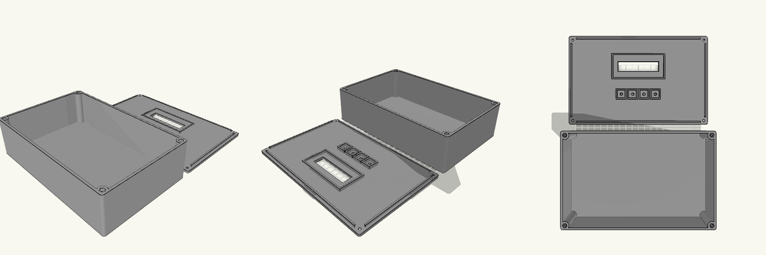
Horizontal LCD Control Enclosure
A horizontal electronic project enclosure designed for control panels and desktop instruments. The assembly features an internal mounting frame for a standard 1602 LCD module and four 12mm tactile push buttons. Components install from the underside of the top cover, ensuring that only the display area and button caps are visible from the exterior. The two-part construction secures together using four M3 screws with captured hex nuts embedded in the bottom housing. Overall dimensions: 220mm × 140mm × 60mm Hardware required: 4× M3 screws, 4× M3 hex nuts Component mounts: 1602 LCD PCB (80x36mm) and 4× 12mm tactile switches Print orientation: Both parts print flat on the build plate without supports
SafeSuit Pro Controller Housing
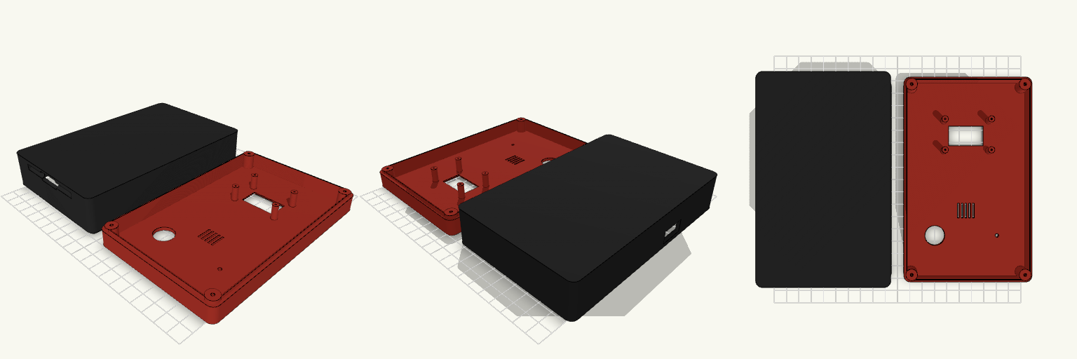
A loose development board is just a short circuit waiting for a metallic desk. This is a heavy-duty, two-piece wearable housing designed to bolt an ESP32 and LoRa radio down tight, run the cables clean, and put the interface exactly where you can hit it blind. Assembly Clearances Dimensions: 160 × 100 × 45 mm assembled. Screen: 28×16 mm inner cutout with a 32×20 mm outer recess for a flush bezel (fits standard 0.96" I2C OLEDs). Fasteners: Eight 2.5mm ID corner bosses ready for M3 tapping, completely blind from the front face. Printing: Both halves sit flat on the bed. Flip the front cover 180° in your slicer to print face-down without supports.
VL53L0X ToF Sensor Enclosure
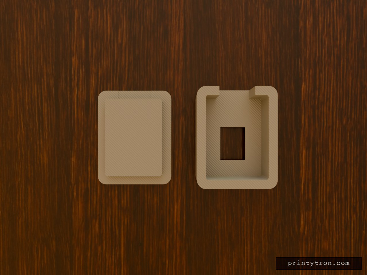
A compact, two-piece enclosure designed for standard VL53L0X Time-of-Flight breakout boards. It provides full protection for the PCB while maintaining a wide, unobstructed field of view for the optical sensor. What it's for Built to house a downward-facing ToF sensor. The flared aperture prevents the enclosure walls from clipping the sensor's ~25-degree conical field of view, while the flat backplate provides a clean surface for double-sided mounting tape. Dimensions Maximum Board Size: 14 mm × 19 mm (fits standard generic and Pololu breakouts) Internal Depth: 7 mm (plenty of room for direct-soldered wire joints) External Size: 18 mm × 23 mm × 9 mm (assembled) Sensor Aperture: 6 mm × 8 mm at the PCB, flaring out to 12 mm × 14 mm at the exterior Cable Routing: 8 mm wide exit slot on one end Print notes Print both parts flat on the build plate. The main body prints sensor-face down; the internal ceiling spans only 14 mm and will bridge cleanly on any well-calibrated machine without requiring supports. The lid includes a small clearance lip for a gentle friction fit.
双风扇免螺丝网络设备外壳
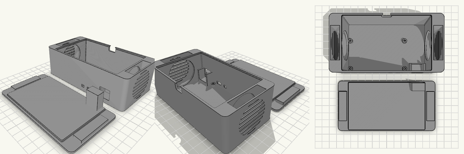
一个为带有双40mm散热风扇和WT32-ETH01模块设计的设备底盒与盖板套装。 尺寸空间:内部预留 10.5 × 6.5 cm 的主板空间。 散热结构:左右两侧外扩式双风扇舱,支持 40×40×10mm 风扇像抽屉一样从下方滑入,外侧配有防触碰百叶栅格。 固定方式:底盒内集成 4 个盲孔定位柱用于垫高和安放主板,网口处设有 U 型支撑座。 免螺丝锁紧:分体式顶盖自带卡扣,盖合时顶盖内侧的下压柱会直接抵住网口金属壳,实现内部模块的免螺丝固定。

Futuristic Handheld Cyberdeck Enclosure
This enclosure turns standard portable electronics into a futuristic clamshell cyberdeck, styled after classic oversized handheld gaming consoles. The design features: A Lower Deck with a recessed keyboard well, flanked by integrated D-pad, thumbstick, and action button mounts. An Upper Display Shell with a wide screen recess and slim bezels. An integrated barrel hinge mechanism that visually connects the two halves while keeping the closed profile slim and symmetrical. Edge ports and bottom cooling vents designed for FDM printing without bulky overhangs. Print the halves flat on their outer faces. The hinge uses standard 12mm barrel clearances.
DataStack — Enclosure Core
A lightweight, 4-bay enclosure body for 2.5" SATA HDDs. Features Stripped-down chassis with extensive material-saving cutouts Integrated rails for 4 drives Rear bosses for mounting a custom PCB backplane Designed to be printed on end (resting on the back faces) to avoid internal supports.