PK360 Combustion Engine adapter
Created 1 months ago
Remixed 7 times
Description
Allows connecting combustion engine grill fan to a pk360 grill intake vent
Photos
Technical views
More like this
Explore more in Home & Fixtures →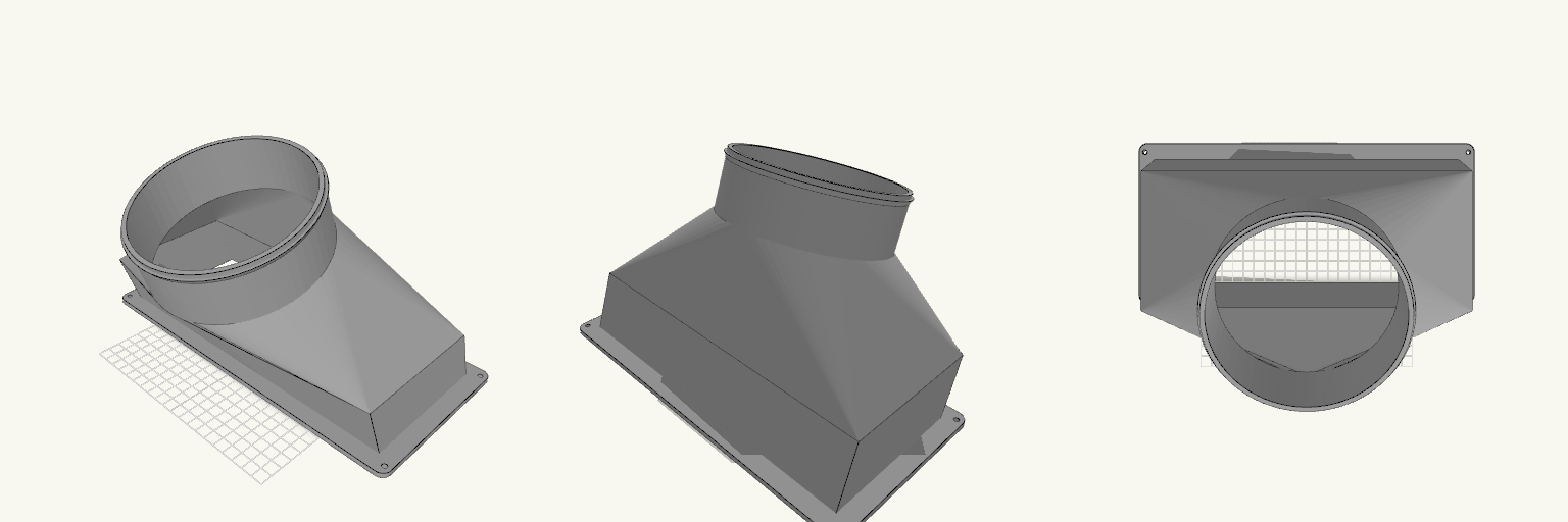
Klarstein DryFy 50L 150 mm Exhaust Adapter
Rectangular-to-round exhaust adapter for routing a 150 mm vent hose from a Klarstein DryFy Connect 50L dehumidifier. The part bolts over the unit's 285 × 120 mm rectangular exhaust port and rises through a 50 mm straight rectangular section before lofting to a round spigot that slides inside a 150 mm hose. The rectangular body leans 20° toward -Y, and the spigot carries a further 20° tilt in the same direction, so the hose leaves the unit well off vertical. The rear of the spigot is pulled back into line with the rear wall of the leaning body, so the back of the adapter is one straight, continuous face with no bulge or kink at the transition; the front still curves as the rectangle narrows to the round spigot. The flange sits flat on the print plate; the overhanging body and spigot will need support. Specifications Overall size: 315 × 220.9 × 186.3 mm as it sits on the print plate Mounting flange: 315 × 150 mm, 4 mm thick, sized to cover a 285 × 120 mm rectangular port Four 4.5 mm screw holes, one in each flange corner Straight rectangular section: 50 mm tall above the flange, leaned 20° toward -Y Transition: 60 mm loft from the rectangle to a round spigot Hose spigot: 148 mm outside diameter, 50 mm long, set at 20° toward -Y on top of the body lean, for a 150 mm hose Combined body lean and spigot tilt put the hose axis roughly 40° off vertical, toward -Y Straight back face: spigot rear wall aligned with the rear wall of the leaning body Retaining ridge near the spigot end Wall thickness: 2.4 mm The angled spigot ends in an elliptical cut face; the hose slides on along the tilted axis Flange sits flat on the print plate; supports required under the leaning body and spigot Screw hole positions are a nominal layout; check them against the actual port before printing if an exact screw match is required The rectangle-to-round change is steep over 60 mm; expect visible stepping on the loft unless printed with fine layers Check that the angled spigot clears the wall or obstructions behind the unit before printing
Barbed End Plug for 1-Inch PEX
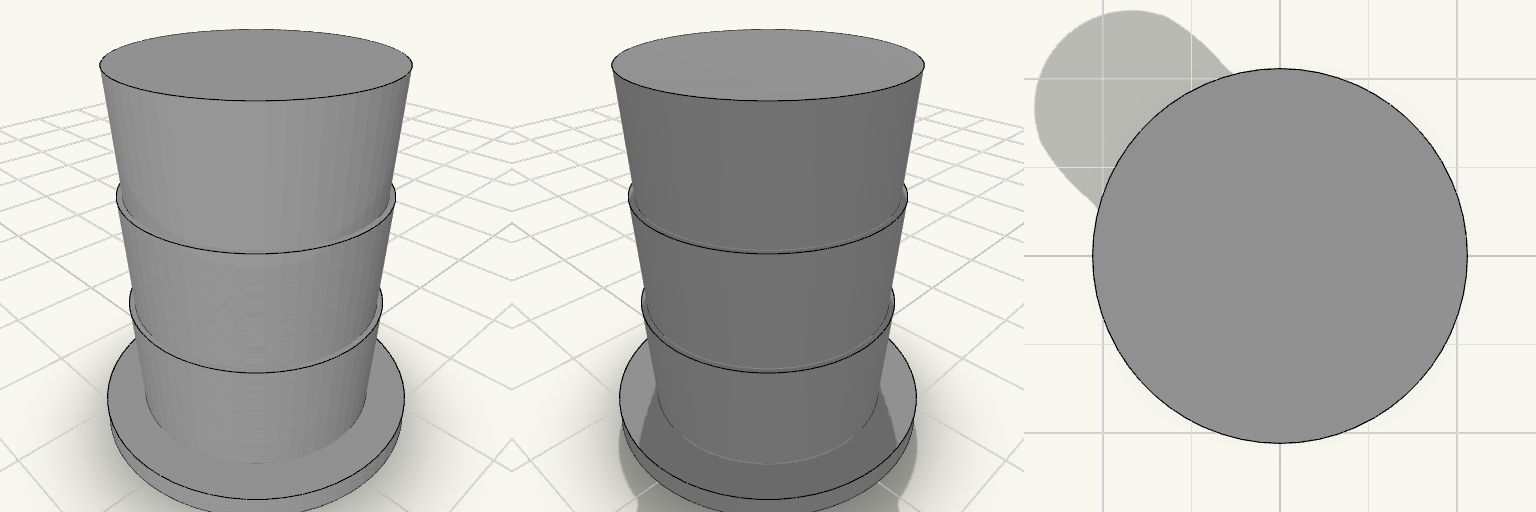
A barbed end plug that dead-ends a 1-inch PEX line. Three tapered barbs rise from a solid 28 mm collar cap, stacked directly on one another so each ring sits flush against the next with no gaps, and they taper from 21 mm to a 22 mm maximum diameter to suit pipe with roughly a 22 mm inner diameter. The collar is a 28 mm cylinder, 3 mm thick, with a 1 mm chamfer on the bottom outer edge, and it is the cap as well as the pipe stop — only about 3 mm of it shows past the barbs, so the stop is shallow. There is no bore: the plug is solid through, about 33 mm tall, sits flat on the plate, and prints as one piece as a 28 × 28 × 33 mm body. Because it seals rather than joins, check the barb fit against your actual pipe before committing to a full run. Remix hooks Barb profile: three tapered barbs stacked flush as one sawtooth suit roughly 22 mm inner diameter pipe. Change the count or soften the taper for harder or softer tubing, but keep the spacing equal to the barb height so the gaps between rings do not come back. Collar: 28 mm across and 3 mm thick, it is only just wider than the barbs. Widen or thicken it for a firmer insertion stop; the bottom outer edge carries a 1 mm chamfer, which can be enlarged or removed to change entry feel. Height: 33 mm overall is a compact cap; stretch the straight run above the barbs if you need more insertion room or a deeper seat. Barb diameter: 21–22 mm is the number to change first for other pipe sizes. The collar and barb spacing can stay put while only the taper moves. Ends: the solid cap is the safe baseline. Extending the same barbed profile out the other side turns it back into a straight coupling, and an elbow or tee is a body swap rather than a barb redesign. Fit check: barb dimensions are nominal, so test against your actual pipe before printing a full run. Pairs with: 1-inch PEX runs that need a temporary or permanent dead end, pressure testing, and capping a line before fixtures go on.
Eccentric Duct Adapter 125mm
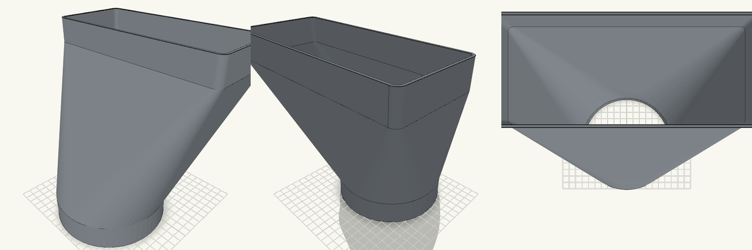
What it's for Bathroom duct adapter that joins a round duct to a flat rectangular duct in one continuous piece. Both ends are female sockets, so the ducts slide into the adapter rather than over it, and the internal passage stays fully open from end to end with no obstruction to airflow. The round socket is bored to Ø132 mm for a free, loose fit over Ø125 mm duct — roughly 3.5 mm of clearance per side, which can be taken up with tape or a gasket if a tighter seal is wanted. Dimensions Round socket: Ø132 mm inner, Ø136.8 mm outer, 30 mm long, 1.5 mm entry chamfer Flat socket: 222 × 92 mm inner, 5 mm corner radius, 30 mm long Transition: 160 mm, smooth round-to-rectangle loft, horizontally symmetric Vertical offset of the flat socket: 72.5 mm Wall thickness: 2.4 mm throughout Overall length: 220 mm Print notes Print as one piece; no assembly and no supports are needed for the open bore. The bounding volume on the plate is about 227 × 189 × 220 mm, so check the build volume before slicing. A 2.4 mm wall prints cleanly in PETG or ABS if the part sees warm bathroom air; PLA works for a dry run-in fit. Remix ideas Change the bore diameter to tune the fit for a different round duct. Adjust the 72.5 mm vertical offset for another mounting position. Lengthen either socket for a deeper grip on the duct.
Doorstop Wedge Rib Clip
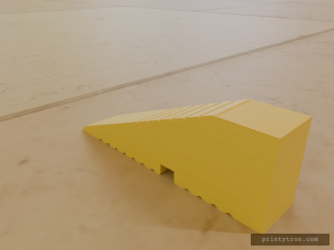
A doorstop wedge with the low, hard-working profile of a chalk wedge, cut to a 10 mm width to grip the raised PVC rib on a balcony door sill. The underside carries a straight snap-fit groove that presses over the rib, the thin tip lets the door glide across, and the block behind it stops the door dead so it cannot swing open while you are out on the balcony. The top rises from a 1 mm tip to a flat 16 mm shelf — the ramp reaches that height about 39.5 mm back from the tip and then runs flat to the fat end. Both the top and bottom faces carry shallow V-ribs across the width: grip where a hand or a door meets the wedge, and a lightly textured finish underneath. Design notes 50 × 10 mm footprint with a 16 mm flat top; the ramp climbs from a 1 mm tip to the shelf, and the shelf’s front edge is left sharp Bottom groove 3.6 mm wide (3.4 mm rib plus 0.2 mm clearance) and 2.5 mm deep, flat-bottomed with a 0.3 mm entry chamfer, centred 20 mm back from the fat end V-ribs run 3 mm apart at 0.4 mm deep; bottom ribs start about 8 mm from the tip and stop clear of the groove so its edges stay clean, while top ribs begin where the wedge is thick enough to cut into 0.5 mm chamfers along the top edges, and a 1 mm 45° bevel at the tip to help the door ride over Printing Print flat on the bottom face with the groove facing down, in PETG at 0.2 mm layers, 4 walls and 40% infill.
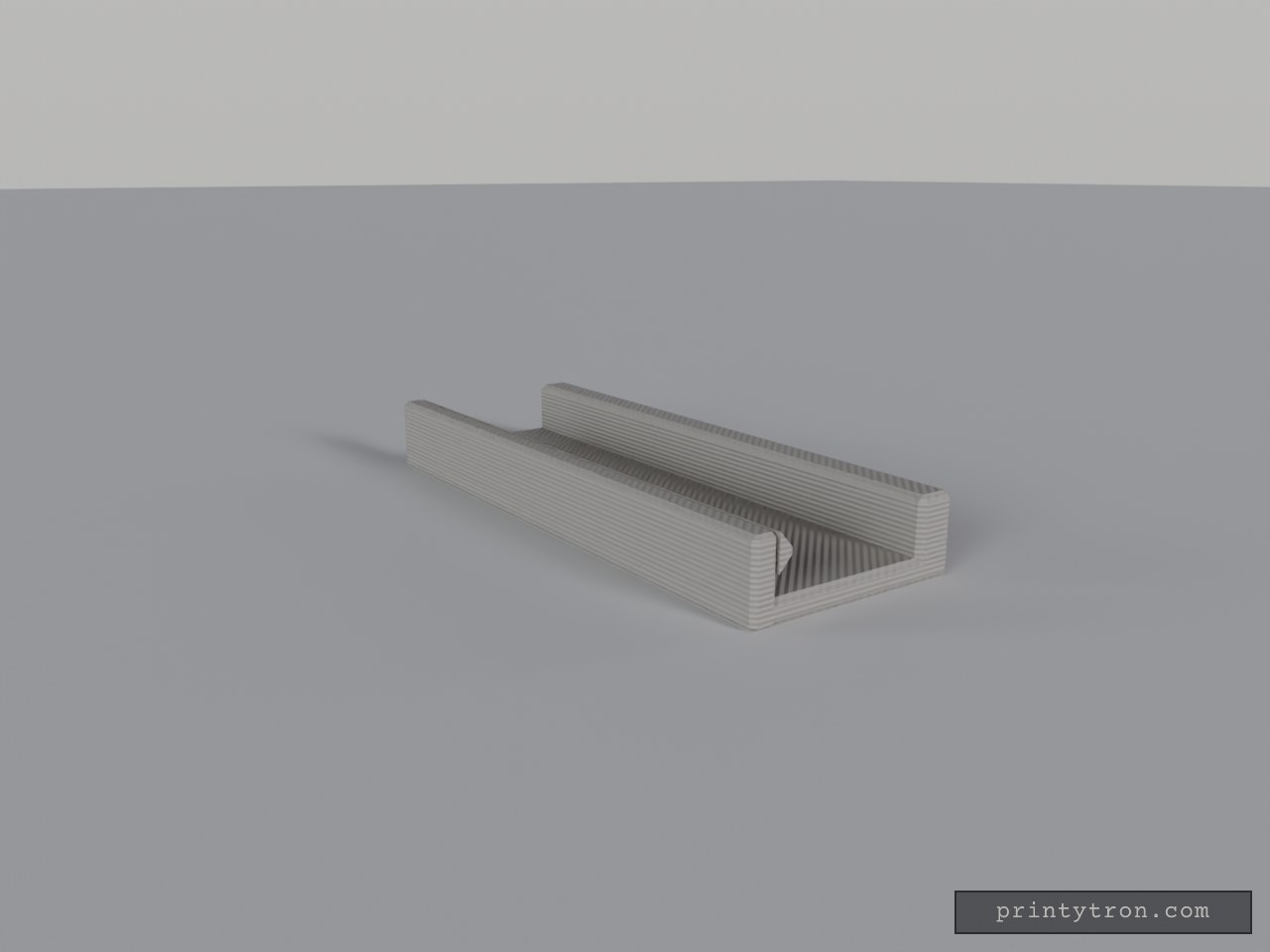
Fly Screen Frame Snap Lock for Wall Gap
A fly-screen frame that keeps popping out of the gap between it and the wall is the annoyance; this clip holds it in line without screws. The frame slides in along the channel from either end, past ramps on a thin flexible arm — it gives way to a deliberate pull but stays put in a gust — and the back carries a glue strip so the clip sits flat against the wall. Fit and hold Channel: 10.2 mm wide for a 1 cm frame, 0.2 mm clearance. Entry: open at both ends, so the frame slides in along the 40 mm length; the arm's lip is ramped down at both ends to start it easily. Front arm: 1.6 mm thick and flexible, fixed only along its base, so the frame opens up easily and still holds in wind. Back wall: rigid, no lip — it stays clear of the sliding frame and only the arm does the holding. Glue recess: 0.8 mm deep and 30 mm long on the back, so the glue strip sits flush and the clip lies flat. Size: 40 × 14.3 × 5 mm, matching the 0.5 cm gap between wall and frame. Use PETG for the flexing front arm — it takes the repeated opening and closing better than a brittle filament, and the stiffness of the arm is what decides whether the frame holds or rattles loose.
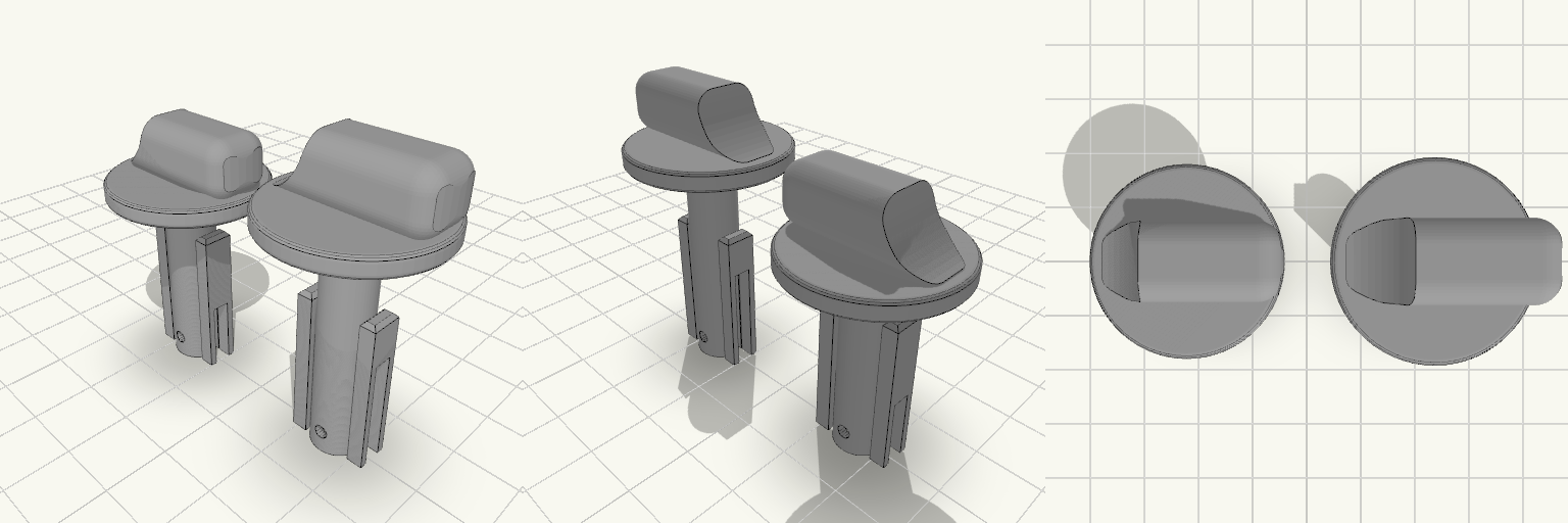
Perilla de estufa de repuesto con vástago reforzado
La perilla de la estufa que gira en falso o se parte deja el fuego sin control; esta perilla de repuesto se calza sobre el caño de gas y se traba con pasador, con el pulgar recortado al contorno del collar y todos los bordes del agarre redondeados para girar sin engancharse. La placa trae dos perillas: la original y una copia con vástago de 35 mm para cambiar el largo según la estufa. Cotas que deciden el calce Dos perillas en la misma placa: la original mide 41,5 mm de alto total (12 mm de cabeza + 29,5 mm de vástago); la copia mide 47 mm de alto total (12 mm de cabeza + 35 mm de vástago). En la placa ocupan 58 × 26 × 47 mm. Vástago: 8 mm de diámetro exterior, con dos aletas planas de refuerzo de 24 mm a los lados; en la copia, las aletas quedan en la zona de la punta. Vástago hueco: orificio de 5,5 mm de diámetro, abierto en la punta. En la original llega a 26 mm de profundidad y queda ciego en los últimos 3,5 mm hacia la cabeza, con paredes de aproximadamente 1,25 mm; la copia mantiene el mismo orificio de 5,5 mm. Agujero pasante: 2,2 mm de diámetro, horizontal, con el centro a 3,5 mm del extremo inferior; cruza la cavidad del vástago, así que la chaveta atraviesa el caño de gas. Endija: 3 mm de ancho, abierta en la punta; va a 90° del agujero del pasador, atraviesa el vástago y corta también las aletas laterales, dejando el extremo dividido en dos mitades flexibles. En la original llega a 11 mm; en la copia llega a 17,5 mm, la mitad de su vástago. Cabeza: collar de 26 mm de diámetro por 3 mm de alto; el pulgar mide 26 mm de ancho, 10 mm de grosor y 9 mm de alto sobre el collar, ya no pasa el contorno del collar, es plano de un lado y baja curvo del otro. Todas las aristas del pulgar tienen 3 mm de radio; los bordes del collar tienen 0,8 mm. Cada perilla se imprime de una sola pieza; la endija no separa el modelo, solo deja flexibles las dos mitades del extremo. El acabado negro mate sale del filamento que elijas, no de la geometría. Antes de imprimir, mide el diámetro del caño de gas y el del pasador: el hueco del vástago y el agujero pasante son las dos cotas que no perdonan, y si no coinciden es mejor ajustarlas antes de gastar material.